ZKTeco TS1000 Pro User Manual
Tripod turnstile
Hide thumbs
Also See for TS1000 Pro:
- User manual (18 pages) ,
- Installation manual (8 pages) ,
- User manual (15 pages)

Subscribe to Our Youtube Channel
Related Manuals for ZKTeco TS1000 Pro


Summary of Contents for ZKTeco TS1000 Pro
- Page 1 User Manual TS1000 Pro Series Tripod Turnstile Version: 1.0 Date: September 2018 1 F16 Quick Start Guide...
-
Page 2: Table Of Contents
Contents 1. Technical Specifications ........................................... 1 2. Unpacking and Testing the Tripod Turnstile ..................................2 2.1 Unpacking ..............................................2 2.2 Arm installation ............................................2 2.3 Power-on test before installation ....................................3 3. Equipment Installation ............................................3 3.1 Installation conditions ......................................... 3 3.2 Cabling ................................................ -
Page 3: Technical Specifications
TS1000 Pro: Tripod Turnstile. TS1011 Pro: Tripod Turnstile with Controller and RFID Reader. TS1022 Pro: Tripod Turnstile with Controller and Fingerprint Reader with RFID function. Please read this document carefully before installation and using the device. 1. Technical Specifications AC 100~120V /200~240V,... -
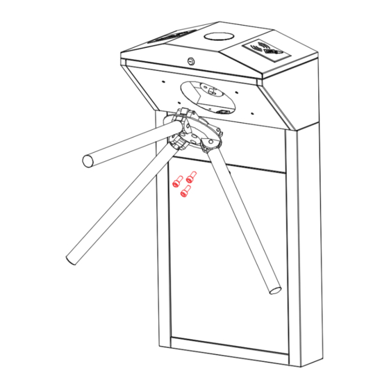
Page 4: Unpacking And Testing The Tripod Turnstile
2. Unpacking and Testing the Tripod Turnstile 2.1 Unpacking The top part of the tripod is heavy, do not remove the foam lining at the bottom before installation, as shown in Figure 2-1. Do not remove the foam lining at the bottom before installation. -
Page 5: Power-On Test Before Installation
2.3 Power-on test before installation Please make sure that the power requirements are strictly met to avoid permanent damages to the unit. Input voltage: AC 100~120V /200~240V. Note: The tripod turnstile must be connected to the ground (earth). Power on and wait 30s for the tripod turnstile to finish the self-check program. Lift the arms manually, as shown in Figure 2-3B. - Page 6 Figure 3-1 Notes: When installing the tripod turnstile against the wall, please reserve a distance of at least 100 mm in order to open the cover for future adjustment and maintenance. The spare space from the end of the arm shall not be greater than 80 mm (see Figure 3-1). You are also recommended to set a warning line for card swiping (see Figure 3-2).
-
Page 7: Cabling
3.2 Cabling There are inlets in the bottom plate for cabling, as shown in Figure 3-3. Units of all data is millimeter. Power supply and communication wire should go through the inlet. Warning: The tripod turnstile must be connected to the ground (earth); there is wiring interface near the power switch. -
Page 8: Cable Diagram
You just need to plug in the communication cable to access the controller and do the settings. If you are using TS1000 Pro, you need to connect the access control system with the control board. Please read the instructions in this chapter carefully. - Page 9 Figure 4-1 Descriptions: J2 Counter: To connect the device with a LED screen and display the number of passages which is generated by each push of tripod arms. Each valid access counts one time. J5 (Right) & J4 (Left) Indicator: To connect a LED screen and indicate whether this person is granted access. J3 Indicator (top): To connect a LED screen and indicate if the user verification is successful and whether the person is granted access.
-
Page 10: Dip K1 Switch Configuration
J8 Proximity Switch Signal Input: Input position signal of the arm. J9 12V Power Supply for Access control: the control board directly provides access control service with 12V power (maximum support 3A). V1L Left Solenoid, V2R Right Solenoid & Drop Arm Solenoid: Control the passage and arm dropping. 4.2 DIP K1 switch configuration Figure 4-2 Function Setting... -
Page 11: Equipment Precautions And Maintenance
4.2.3 Continue passing function With the “Continue Passing” function, the turnstile could remember at most 20 swipes of one card at one time and allows up to 20 people to pass so they don’t have to swipe card each time. This function can be enabled or disabled with number 6 in the DIP switch. -
Page 12: Maintenance
It is recommended to place a warning sign at a conspicuous position, and prompt: "Please swipe your card outside the warning line and pass in order. Thank you!” The maximum stress tolerance of the tripod turnstile's arms Please note that the maximum tolerance at the center and the ends of the arm is 80kg and 40kg, respectively (See Figure 5-1). -
Page 13: Troubleshooting
Turnstile-opening Solenoid Disk Wheel Position Lock Rod Sensor Drop-arm Solenoid Figure 5-2 6. Troubleshooting Symptom Troubleshooting It may be caused by the power supply or circuit. The indicator is not lit when the Check whether the connection cable and power cable are damaged, or equipment is powered on. -
Page 14: Attachment 1 Factory Settings
Attachment 1 Factory Settings Function Default Lock Driving Duration Door Sensor None Verification Interval Controller Communication TCP/IP: 192.168.1.201 Turnstile Opening Duration Passing Direction Indicator Passing is allowed in both directions Continue Passing Function Disabled Alarm Function Disabled Note: The Lock Driving Duration is 5 seconds by default. Please set it to 1 second. Do not connect an electrically charged objects to any ports of Opening Signal Input, otherwise it will damage the control board. -
Page 15: Attachment 2 Connection Diagram Of Control Board And Access Control Panel
Attachment 2 Connection Diagram of Control board and Access Control Panel Warning: This is a class A product. In a domestic environment, this product may cause radio interference so that the user may have to take adequate additional measures. - Page 16 ZK Building, Wuhe Road, Gangtou, Bantian, Buji Town, Longgang District, Shenzhen China 518129 Tel: +86 755-89602345 Fax: +86 755-89602394 www.zkteco.com © Copyright 2018. ZKTeco Inc. ZKTeco Logo is a registered trademark of ZKTeco or a related company. All other product and company names mentioned are used for.
Need help?
Do you have a question about the TS1000 Pro and is the answer not in the manual?
Questions and answers