
Related Manuals for ZKTeco TS1000D


Summary of Contents for ZKTeco TS1000D
- Page 1 TS200 Series Tripod Turnstile User Manual User Manual TS200 Series Tripod Turnstile Date: December 2021 Doc Version: 1.2 English P a g e...
-
Page 2: Table Of Contents
TS200 Series Tripod Turnstile User Manual Table of Contents TECHNICAL SPECIFICATIONS ......................2 UNPACKING AND TESTING THE TRIPOD TURNSTILE ................ 3 ......................................3 NSTALLATION ..............................3 OWER EST BEFORE NSTALLATION EQUIPMENT INSTALLATION ....................... 4 ................................... 4 NSTALLATION ONDITIONS .......................................... 5 ABLING ......................................... -
Page 3: Technical Specifications
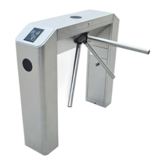
TS200 Series Tripod Turnstile User Manual Please read this document carefully before installation and using the device. Technical Specifications AC 100~120V Input Voltage /200~240V, Arm Length (mm) 50Hz/60Hz Indoor and Operating Environment Dimension(mm) (Figure 1) L=1200, W=280, H=980 Outdoor (shelter) Operating Temperature -28ºC ~ 60ºC Package Size (mm) L=1275, W=370, H=1063... -
Page 4: Unpacking And Testing The Tripod Turnstile
TS200 Series Tripod Turnstile User Manual Unpacking and Testing the Tripod Turnstile Arm Installation In order to prevent the arm from damaging during transportation, the arm will not be initially installed to the devices. Installation procedure Put the arm kit into the hole of cabinet; make sure the screw holes match with mechanism core, then tighten 3 hex screws, as shown in Figure 2-1. -
Page 5: Equipment Installation
TS200 Series Tripod Turnstile User Manual Lift upwards There is a power switch in the side direction of this power supply. Earth wiring terminal Figure 2-2 Equipment Installation Installation Conditions The equipment must be installed on concrete ground, ensuring that expansion bolts can be secured firmly. You are suggested to install an assistant framework or fence to form a passageway, as shown in Figure 3-1. -
Page 6: Cabling
TS200 Series Tripod Turnstile User Manual You are also recommended to set a warning line for card swiping (see Figure 3-2). The warning line prompts users to swipe cards in a particular area, which would greatly reduce the probability of equipment failure caused by improper operations. -
Page 7: Installation
TS200 Series Tripod Turnstile User Manual Installation Drill holes. Drill holes according to the locations of holes as shown in Figure 3-3. Fix the mounting plate to its original position. Place the mounting plate properly, then apply screw securing glue on the surface and threads of the expansion bolts, install four expansion bolts to secure the mounting plate, and use a horizontal ruler to test the levelness of the mounting plate. -
Page 8: Cable Diagram
TS200 Series Tripod Turnstile User Manual Cable Diagram Connection Diagram of the Access Controller Figure 4-1 Note: The lock relay duration of access controller device needs to be set to 1s. Forbidden using electrically charged objects to connect to the port of Opening Signal Input, otherwise will damage the control board. DIP Switch Configuration for SATT-L-V1.1 Figure 4-2 4.2.1... -
Page 9: Opening Mode
TS200 Series Tripod Turnstile User Manual 4.2.2 Opening Mode Card swiping means that you can open the door only after verification. Free means that you can pass the door without verification. Prohibited means that you can't pass the door, whether you have permission or not. -
Page 10: Maintenance
TS200 Series Tripod Turnstile User Manual The maximum stress tolerance of the tripod turnstile's arms Please note that the maximum tolerance at the center and the ends of the arm is 80kg and 40kg, respectively (See Figure 5-1). When the impact force on the tripod turnstile reaches the designed limit, the arms will break down first to ensure that the body of the equipment is not damaged and the passer-by is not injured. -
Page 11: Troubleshooting
TS200 Series Tripod Turnstile User Manual Position Sensor Lock Rod Disk Wheel Turnstile-opening Solenoid Drop-arm Solenoid Figure 5-2 Troubleshooting Symptom Troubleshooting It may be caused by the power supply or circuit. The indicator is not lit when the equipment is Check whether the connection cable and power cable are damaged, or powered on. -
Page 12: Attachment 1 Factory Settings
TS200 Series Tripod Turnstile User Manual Attachment 1 Factory Settings Function Default Lock Driving Duration Door Sensor None Verification Interval Controller Communication TCP/IP: 192.168.1.201 Turnstile Opening Duration Passing Direction Indicator Passing is allowed in both directions Continue Passing Function Disabled Alarm Function Disabled Note: The Lock Driving Duration is 5 seconds by default. -
Page 13: Attachment 2 Connection Diagram Of Control Board And Access Control Panel
TS200 Series Tripod Turnstile User Manual Attachment 2 Connection Diagram of Control Board and Access Control Panel Warning: This is a class a product. In a domestic environment, this product may cause radio interference so that the user may have to take adequate additional measures. P a g e | 12...
Need help?
Do you have a question about the TS1000D and is the answer not in the manual?
Questions and answers