Advertisement
Quick Links
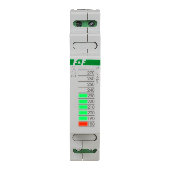
WN-711S
Voltage indicator,
1-phase
Do not dispose of this device in the trash along with other waste! According
to the Law on Waste, electro coming from households free of charge and
can give any amount to up to that end point of collec� on, as well as to sto-
re the occasion of the purchase of new equipment (in accordance with the
principle of old-for-new, regardless of brand). Electro thrown in the trash or
abandoned in nature, pose a threat to the environment and human health.
Purpose
The WN-711S voltage indicator is designed for continuous me-
asurement and optical visualization of the voltage value in a sin-
gle-phase network.
Functioning
The indicated voltage range is 180÷270 V with a reading accura-
cy of 10 V. The switched on LED light indicates the voltage value
described on its height. The voltage value between 190 V and
260 V is indicated by the green LEDs. The extreme values 180 V
and 270 V are indicated by a red LED. Voltage lower than 180 V
is indicated by the 180 V red LED flashing. Voltage higher than
270 V is indicated by the flashing of the diode located at the top.
The device can operate in "bar" or "single diode" mode. The se-
lection is made by shorting (or not) terminals 10-12.
F&F Filipowski sp. j.
Konstantynowska 79/81, 95-200 Pabianice, POLAND
phone/fax (+48 42) 215 23 83 / (+48 42) 227 09 71
www.fif.com.pl; e-mail: biuro@fif.com.pl
- 1 -
Advertisement

Related Manuals for F&F WN-711S


Summary of Contents for F&F WN-711S
- Page 1 Electro thrown in the trash or abandoned in nature, pose a threat to the environment and human health. Purpose The WN-711S voltage indicator is designed for continuous me- asurement and optical visualization of the voltage value in a sin- gle-phase network.
- Page 2 Operating modes "Bar" mode, "Single diode" mode, connection "without jumper" connection "with jumper" Triggering indication Voltage value is shown for 10 seconds, when you touch the F&F logo on the front of the housing - 2 -...
- Page 3 Mounting 1. Disconnect the power supply. 2. Install the indicator on the rail in the distribution board. 3. Connect the power wires according to the diagram. 4. Select the device mode (terminals 10-12). 5. Switch on the power supply and verify that the device is wor- king correctly.
- Page 4 Technical data power supply 85÷265 V AC voltage indicator 10×LED measurement error <2% power consumption <1 W working temperature -25÷50°C terminal 2.5 mm² screw terminals tightening torque 0.4 Nm dimensions 1 module (18 mm) mounting on TH-35 rail ingress protection IP20 Warranty F&F products are covered by a 24-month warranty from the date...