Advertisement
Quick Links
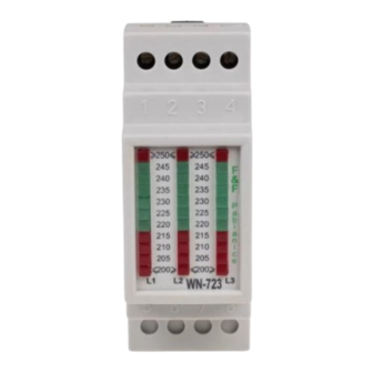
WN-723
Voltage indicator,
3-phase
Do not dispose of this device in the trash along with other waste! According
to the Law on Waste, electro coming from households free of charge and
can give any amount to up to that end point of collec� on, as well as to sto-
re the occasion of the purchase of new equipment (in accordance with the
principle of old-for-new, regardless of brand). Electro thrown in the trash or
abandoned in nature, pose a threat to the environment and human health.
Purpose
The WN-723 voltage indicator is designed for continuous measu-
rement and optical visualization of the voltage value in a 3-phase
network.
Functioning
The indicated voltage range for each phase is from 205÷245 V
with a reading accuracy of 2.5 V. The illumination of the LED indi-
cates voltage value described on its height. If 2 LEDs are on, the
voltage value is the average of the values described on their he-
ights. The voltage value within the tolerance (215 V to 245 V) is
indicated by the lighting of the LEDs green LEDs are lit, and other
values are indicated by the lighting of the red. Voltage equal to
or higher than 250 V is indicated by indicated by the illumination
of the highest red LED (≥). Voltage equal to or lower than 200 V
is indicated by the lighting of the lowest red LED (≤).
F&F Filipowski sp. j.
Konstantynowska 79/81, 95-200 Pabianice, POLAND
phone/fax (+48 42) 215 23 83 / (+48 42) 227 09 71
www.fif.com.pl; e-mail: biuro@fif.com.pl
- 1 -
Advertisement

Related Manuals for F&F WN-723


Summary of Contents for F&F WN-723
- Page 1 Electro thrown in the trash or abandoned in nature, pose a threat to the environment and human health. Purpose The WN-723 voltage indicator is designed for continuous measu- rement and optical visualization of the voltage value in a 3-phase network.
- Page 2 Mounting 1. Check the phase sequence. 2. Disconnect the power supply. 3. Install the indicator on the rail in the distribution board. 4. Connect the power wires according to the diagram. 5. Switch on the power supply and verify that the device is wor- king correctly.
- Page 3 Technical data power supply 3×230 V+N voltage indicator 3× (11×LED) indication range 205÷245 V scale reading accuracy 2.5 V power consumption 0.8 W working temperature -25÷50°C terminal 2.5 mm² screw terminals (cord) 4.0 mm² screw terminals (wire) tightening torque 0.5 Nm dimensions 2 modules (35 mm) mounting...
Need help?
Do you have a question about the WN-723 and is the answer not in the manual?
Questions and answers