
Related Manuals for ICOP Technology VDX3-6724-V2


Summary of Contents for ICOP Technology VDX3-6724-V2
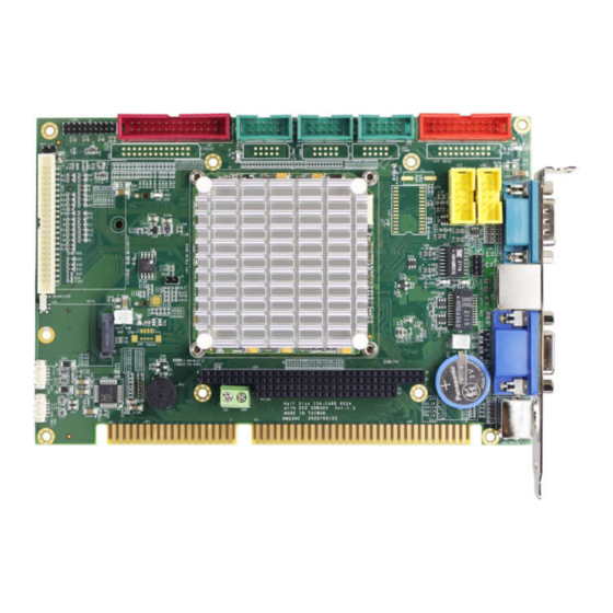
- Page 1 User Manual VDX3-6724-V2 with DM&P Vortex86DX3 1GHz processor Half-Size CPU Module with 4S/4USB/VGA/LCD/LVDS/ AUDIO/2LAN/GPIO/ 1/2GB DDR3 Onboard Version 3.0 ICOP Technology Inc.
- Page 2 No part of this manual may be reproduced, copied, translated or transmitted, in whole or in part, in any form or by any means without the prior to written permission of ICOP Technology Inc. Copyright ⓒ 2016 ICOP Technology Inc Trademarks Acknowledgement Vortex86DX3 is the registered trademark of DM&P Electronics Inc.
- Page 3 First release New Add: June 8, 2016 (1) Working temperature for Dual Core version (2) Cable set for VDX3-6724 with Compact Flash October 12, Change P/N to VDX3-6724-V2 due to Audio codec and 2022 GbE controller change ICOP Technology Inc.
-
Page 4: Table Of Contents
J12: USB2&3 ..........................17 J13: GPIO (Port 6/7) ........................17 J15: RESET ........................... 17 J17: COM1 RS232/485 D-Sub 9 pin ....................18 J18: COM2 RS232/485 ........................18 J20: COM5 RS232 .......................... 18 J22: COM6 RS232 .......................... 18 ICOP Technology Inc. - Page 5 4.2.4 Serial Ports Switching ........................ 31 4.2.5 IDE Configuration ........................32 4.2.6 Advanced PCI/PnP Setting ....................... 34 4.2.7 ACPI Enable ..........................35 4.2.8 LCD Panel Setting ........................36 Appendix ........................38 Stacking Solution for Daughter Board ....................38 Warranty ........................40 ICOP Technology Inc.
-
Page 6: General Information
SATA, I2C, VGA, LVDS, PS/2, USB, HD Audio and even with 16-bit ISA bus support. The VDX3-6724 is designed as a plug in replacement, with backward compatibility to support legacy software to help extend existing product life cycle without heavy re-engineering. 1.2 Block diagram Board Block Diagram ICOP Technology Inc. -
Page 7: Specifications
2-pin box header for DC +5V output x1 15-pin D-Sub female connector for VGA x1 9-pin D-Sub male connector for RS232 x1 Type I/II Compact Flash slot x1 (Optional) Terminal block for DC input x1 PS/2 connector for Keyboard/Mouse x1 ICOP Technology Inc. - Page 8 -20°C to +70°C (Optional for Dual Core) Dimensions 184 x 122mm Weight 180g Windows 7 Linux Windows Embedded Compact 7 Windows XP Professional POS Ready (WePOS) O/S Support Windows Embedded Standard 7 Windows Embedded 2009 VxWorks Free BSD ICOP Technology Inc.
-
Page 9: Ordering Information
Audio Line x2 Printer (2.54) x1 RS-232 (2.54) x3 CABLE-6724-CF USB (2.54) x2 Audio Line x2 NET 4x2 (2.0) x1 *Default setting for processor on VDX3-6724 is Single-core. If Dual-core processor is required, please contact ICOP (info@icop.com.tw). ICOP Technology Inc. - Page 10 VDX3-6724-V2 User Manual Storages: Product Name 0°C to +70°C -40°C to +85°C ISATA-8G-H-M ISATA-16G-H-M ISATA-32G-H-M ISATA-4G-H-M-X ISATA-8G-H-M-X ISATA-16G-H-M-X ISATA-32G-H-M-X ISATA-1G-H-S ISATA-2G-H-S ISATA-4G-H-S ISATA-8G-H-S ISATA-16G-H-S Demonstration of SATA DoM on VDX3-6724 ICOP Technology Inc.
-
Page 11: Hardware Information
VDX3-6724-V2 User Manual 2 Hardware Information 2.1 Board Dimension ICOP Technology Inc. -
Page 12: Board Outline
(optional) is selected. 3. GPIO will be occupied when eMMC is selected on VDX3-6724. 4. LPT, eMMC, and GPIO are not available on VDX3-6724-CF. 5. CF card slot is only available on VDX3-6724-CF. (see the image below) ICOP Technology Inc. - Page 13 VDX3-6724-V2 User Manual VDX3-6724-V2-CF TOP VIEW BOTTOM VIEW ICOP Technology Inc.
-
Page 14: Connector Summary
PC104 Connector – 40 pins Box Header, 2.54mm, 20x2 Line-Out Wafer, 1.25mm, 4x1 MIC-In Wafer, 1.25mm, 4x1 Touch screen Controller Wafer, 1.25mm, 4x1 (Optional) Parallel Box Header, 2.0mm, 13x2 Master/Slave for CF Card Slide switch CF card slot Buzzer ICOP Technology Inc. -
Page 15: Pin Assignments & Jumper Settings
VDX3-6724-V2 User Manual 2.4 Pin Assignments & Jumper Settings J1: LCD Pin# Signal Name Pin # Signal Name +3.3V +3.3V LCLK LHSYNC LVSYNC LBACKL LVDDEN (Please refer to Appendix for TFT Flat Panel Data Output) ICOP Technology Inc. -
Page 16: J2: Vga
DDCCLK J3: LVDS (24-bit Support Only) Pin# Signal Name Pin # Signal Name VCC3 (+3.3V) VCC3 (+3.3V) RxIN0+ RxIN0- RxIN1- RxIN1+ RxIN2+ RxIN2- CKIN- CKIN+ RxIN3- GxIN3+ J4: SATA DOM Pin# Signal Name Pin # Signal Name ICOP Technology Inc. -
Page 17: J6: Sata Dom Power
Pin # Signal Name J10: LAN2 (10/100) Pin# Signal Name Pin # Signal Name ATX+ ATX- ARX+ LED0 LED0+ ARX- LED1+ LED1 J11: USB0&1 Pin# Signal Name Pin # Signal Name LUSBD0- LUSBD0- LUSBD0+ LUSBD1+ GGND GGND ICOP Technology Inc. -
Page 18: J12: Usb2&3
GP61 GP71 GP62 GP72 GP63 GP73 GP64 GP74 GP65 GP75 GP66 GP76 GP67 GP77 *When onboard eMMC is enabled, GPIO will be disabled. **Not available on VDX3-6724-CF J15: RESET Pin# Signal Name Pin # Signal Name RST_SW ICOP Technology Inc. -
Page 19: J17: Com1 Rs232/485 D-Sub 9 Pin
(Optional: TTL/ GPIO-P6) Pin# Signal Name Pin # Signal Name DCD5 RXD5 TXD5 DTR5 DSR5 RTS5 CTS5 J22: COM6 RS232 (Optional: TTL/ GPIO-P1) Pin# Signal Name Pin # Signal Name DCD6 RXD6 TXD6 DTR6 DSR6 RTS6 CTS6 ICOP Technology Inc. -
Page 20: J24A: Pc/104 Connector - 64 Pin
SMEMR* DRQ5 SA18 IOW* DACK6* SA17 IOR* DRQ6 SD10 SA16 DACK3* DACK7 SD11 SA15 DRQ3 DRQ7 SD12 SA14 DACK1* SD13 SA13 DRQ1* MASTER* SD14 SA12 REFRESH* SD15 SA11 SYSCLK SA10 IRQ7 IRQ6 IRQ5 IRQ4 IRQ3 DACK2* BALE ICOP Technology Inc. -
Page 21: J28: Line-Out
J28: Line-out J29: MIC-in Pin# Signal Name Pin# Signal Name LOUTR MICVREF LOUTL MIC-IN J30: Touch screen (Optional) Pin# Signal Name *Onboard SPI ROM (optional) and PS/2 Mouse will be disabled when Touch function (optional) is selected. ICOP Technology Inc. -
Page 22: J31: Parallel
VDX3-6724-V2 User Manual J31: Parallel Pin# Signal Name Pin # Signal Name STB- AFD- ERR- INIT- SLIN- ACK- BUSY SLCT *Not available on VDX3-6724-CF ICOP Technology Inc. -
Page 23: System Mapping
000E0000 – 000EFFFF USB Legacy SCSI ROM space 000F0000 – 000FFFFF Motherboard BBIOS FEFDBC00 – FEFDBCFF Standard OpenHCD USB Host Controller FEFBB400 – FEFBB4FF Onboard Ethernet Adapter FEFDB800 – FEFDBFFF Standard Enhanced PCI to USB Host Controller ICOP Technology Inc. - Page 24 DMA High page register 0490h – 0499h Instruction counter register 04D0h – 04D1h 8259 Edge / level control register 0CF8h – 0CFFh PCI configuration port DE00h – DEFFh On board LAN FC00h – FC05h SPI Flash BIOS control register ICOP Technology Inc.
- Page 25 Real Timer Clock IRQ9 ACPI IRQ10 Serial Port 3 IRQ11 Serial Port 4 IRQ12 Mouse IRQ13 Math Coprocessor IRQ14 Multimedia Device IRQ15 Hard Disk Controller #2 DMA Mapping Address Description Usage DMA0 DMA1 DMA2 DMA3 DMA4 DMA5 DMA6 DMA7 ICOP Technology Inc.
-
Page 26: Software Resources
Vortex86 processor. This programming guide also includes the installation guide for X-Linux, Debian & Ubuntu Linux guide and board support package (BSP) for Windows Embedded OS on Vortex86SX/DX/DX2/DX3. For details, please kindly visit the following link: http://www.dmp.com.tw/tech/ ICOP Technology Inc. -
Page 27: Technical Support
1920 x 1080 (at 60MHz) connecting to LCD Flat Panel: 18-bit/24-bit TFT-LCD and 24-bit LVDS. 4.1.2 Pin Assignment of LVDS and TFT-LCD LVDS Pin Assignment LVDS Pin# Pin Name LVDS Pin# Pin Name VCC3(3.3V) VCC3(3.3V) CLK- CLK+ ICOP Technology Inc. - Page 28 LCD Pin# Vortex86DX3 Pin Name DIGITAL 18 bits RGB 24 bits LCDVCC (+3.3V) LCDVCC (+3.3V) FPD12 FPD13 FPD14 FPD15 FPD16 FPD17 FPD18 FPD19 FPD20 FPD21 FPD22 FPD23 PPD0 PPD1 PPD2 PPD3 PPD4 PPD5 PPD6 PPD7 PPD8 PPD9 PPD10 PPD11 ICOP Technology Inc.
- Page 29 VDX3-6724-V2 User Manual FP1CLK XCLK XCLK FP1DE FP1HS HSYNC HSYNC FP1VS VSYNC VSYNC FPENBLT FPENVDD VDDEN VDDEN ICOP Technology Inc.
-
Page 30: Bios Introduction
VGA display or monitor. The default access port is COM1 and disabled. If you would like to use this function, please go to the path below to enable Console Redirection. Path: Advanced >Remote Access Configuration >Remote Access [Enabled] ICOP Technology Inc. -
Page 31: Serial Ports Switching
Serial ports on VDX3-6724 are set RS232 as default. If you need RS485 to be your default serial ports, you can refer to the below instruction to change it according to your demands. Path: Advanced > Serial/Parallel Port Configuration ICOP Technology Inc. -
Page 32: Ide Configuration
If you would like to use Linux on VDX3-6724, please follow below instructions: Onboard IDE Operate Mode: [Native Mode] IDE Compatibility: [Enabled]. Path of Onboard IDE Operate Mode: Advanced > IDE Configuration > IDE Operate Mode [Native Mode] ICOP Technology Inc. - Page 33 VDX3-6724-V2 User Manual Path of IDE Compatibility: Advanced > IDE Compatibility [Enabled] IDE Configuration > ICOP Technology Inc.
-
Page 34: Advanced Pci/Pnp Setting
Advanced PCI/PnP Setting Two statuses for IRQ setting: [Reserved]: IRQ will be free to be allocated by ISA device, not PCI device. [Available]: IRQ will be allocated by both ISA device and PCI device. Path: PCIPnP >IRQ ICOP Technology Inc. -
Page 35: Acpi Enable
VDX3-6724-V2 User Manual 4.2.7 ACPI Enable To install Windows 7 on ICOP computer boards, please enable ACPI as the following instruction. Path: Advanced > ACPI Configuration >ACPI Aware O/S ICOP Technology Inc. -
Page 36: Lcd Panel Setting
Resolution of the LCD Panel 640 x 480 800 x 480 800 x 600 1024 x 600 1024 x 768 Path of Boot Display Device setting: Chipset > NorthBridge Configuration > VGA Configuration > Boot Display Device [IPD] ICOP Technology Inc. - Page 37 VDX3-6724-V2 User Manual Path of LCD Panel Index setting: Chipset > NorthBridge Configuration > VGA Configuration > LCD Panel Index [ ICOP Technology Inc.
-
Page 38: Appendix
Stacking Solution for Daughter Board 1. Please prepare PC104L40P x 1 and PC104L64P x 1 (as the image below shown). PC104L64P PC104L40P 2. Put on the nuts, pillars, screws and PC104 connector (as the image below shown) ICOP Technology Inc. - Page 39 VDX3-6724-V2 User Manual 3. As the image below shown after stacking. Note: Please contact ICOP if the nuts, pillars and screws are required. ICOP Technology Inc.
-
Page 40: Warranty
Returned goods should always be accompanied by a clear problem description. Should you have questions about warranty and RMA service, please contact us directly. ICOP Technology Inc. Address: No. 15 Wugong 5th Road, Xinzhuang Dist. New Taipei City, Taiwan (R.O.C.) 24890...
Need help?
Do you have a question about the VDX3-6724-V2 and is the answer not in the manual?
Questions and answers