
Related Manuals for ICOP Technology QEC-M-01


Summary of Contents for ICOP Technology QEC-M-01
- Page 1 ICOP Technology Inc. User Manual QEC-M-01 DM&P Vortex86EX2 Processor EtherCAT Master System (Revision 2.2) QEC-M-01 User Manual Ver 2.2 January, 2024...
- Page 2 ICOP Technology Inc. REVISION DATE VERSION DESCRIPTION 2022/06/24 Version1.0A First Release. 2023/03/28 Version1.1A Modified Start Guide. 2023/08/08 Version2 Updated Product Specifications. 2023/11/05 Version2.1 Updated Hardware system. 2024/01/14 Version2.2 Updated Getting Started. QEC-M-01 User Manual Ver 2.2 January, 2024...
- Page 3 No part of this manual may be reproduced, copied, translated or transmitted, in whole or in part, in any form or by any means without the prior written permission of ICOP Technology Inc. ©Copyright 2024 ICOP Technology Inc. Ver.2.2 January, 2024 TRADEMARKS ACKNOWLEDGMENT ICOP®...
- Page 4 WARNING! DO NOT ATTEMPT TO OPEN OR TO DISASSEMBLE THE CHASSIS (ENCASING) OF THIS PRODUCT. PLEASE CONTACT YOUR DEALER FOR SERVICING FROM QUALIFIED TECHNICIAN. QEC-M-01 User Manual Ver 2.2 January, 2024...
-
Page 5: Table Of Contents
2.3.2 Removing the wire from the connector ................16 Ch. 3 Hardware Installation ....................17 3.1 DIN-Rail installation ....................18 3.2 Removing QEC-M-01 Unit ..................19 Ch. 4 Getting Started......................20 4.1 Package Contents ....................22 4.2 Hardware Configuration ..................22 4.2.1 Plug in the power supply .................... - Page 6 4.5.4 Distributed Clock (DC) ....................35 4.5.5 Use 86EVA with code ..................... 38 4.6 Troubleshooting ....................46 4.6.1 Old environment of your QEC-M-01: ................46 Ch. 5 Software Function ....................48 5.1 Software Description ................... 49 5.2 EtherCAT Function List ..................50 EthercatMaster Class Functions ....................
-
Page 7: 1 General Information
ICOP Technology Inc. General Information 1.1 Introduction 1.2 Specifications 1.3 Dimension 1.4 Mounting Instruction 1.5 Ordering Information QEC-M-01 User Manual Ver 2.2 January, 2024... -
Page 8: Introduction
QEC-M-01 has a built-in high endurance 2GB SLC eMMC, designed to provide a stable and reliable operating system. Users can upload the developed executable files and required images or data, such as HMI images, to the QEC-M-01’s SLC via the 86Duino IDE without affecting the performance of the master system. -
Page 9: Qec-M Systems Diagram
QEC-M, and it runs on Windows, Mac OS X, and Linux. The environment is written in Java and based on Arduino IDE, Processing, DJGPP, and other open-source software. You can Download here: https://www.qec.tw/software/. QEC-M-01 User Manual Ver 2.2 January, 2024... -
Page 10: Specifications
CE, FCC, VCCI Internal Monitoring Temperature, Voltage, Current Certifications CE, FCC, VCCI 86Duino Coding IDE 500+ Software Support (The environment is written in Java and based on Arduino IDE, Processing, DJGPP, and other open-source software) QEC-M-01 User Manual Ver 2.2 January, 2024... -
Page 11: Dimension
ICOP Technology Inc. 1.3 Dimension (Unit: mm) QEC-M-01 User Manual Ver 2.2 January, 2024... -
Page 12: Mounting Instruction
ICOP Technology Inc. 1.4 Mounting Instruction QEC-M-01 is an easy-install design to help you maintain your modules easily. Please refer to Ch.3.1 DIN-Rail installation. DIN-Rill QEC-M-01 User Manual Ver 2.2 January, 2024... -
Page 13: Ordering Information
ICOP Technology Inc. 1.5 Ordering Information (Below is the customization function, the unfilled fields do not need to be filled in; if the customer does not require, it will be directly shipped standard material number, such as QEC-M-01) Type LCD size... -
Page 14: 2 Hardware System
ICOP Technology Inc. Hardware System 2.1 General Technical Data 2.2 Connector Summary 2.3 Wiring to the Connector QEC-M-01 User Manual Ver 2.2 January, 2024... -
Page 15: General Technical Data
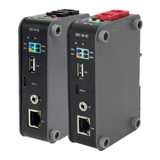
Power and Connection Status LEDs External Status LEDs RS-485 Terminal Block Interface 4-pin Standard USB 2.0 Micro USB Micro USB (Type-B) Audio HD Audio Giga LAN External RJ45 Connector 8-pin (Gold finger) DIN-Rail QEC-M-01 User Manual Ver 2.2 January, 2024... -
Page 16: Ethercat Interface
Pin # Signal Name LAN2_TX+ LAN2_TX- LAN2_RX+ LAN2_RX- VS- (GND) VP- (GND) PoE LAN with the Red Housing; Regular LAN with Black Housing. L4, L5, L7, L8 pins are option, for RJ45 Power IN/OUT. QEC-M-01 User Manual Ver 2.2 January, 2024... -
Page 17: Power Connector
Vs for system power; Vp for peripheral power and backup power. Pin # Signal Name Pin # Signal Name Vs- (GND) Vp- (GND) Power Input voltage +19 to +50VDC Power Input (Typ. +24VDC) QEC-M-01 User Manual Ver 2.2 January, 2024... -
Page 18: Power And Connection Status Leds
There are two LED for each LAN ports. Please refer to the table below for the LAN port LED indications. Notation Color States Description Green Green LED Blinking Data Activity LINK Orange Orange LED On 100Mbps Connection Green Green LED Blinking Data Activity LINK Orange Orange LED On 100Mbps Connection QEC-M-01 User Manual Ver 2.2 January, 2024... -
Page 19: Rs-485
To setup RS-485 pins, please refer to Serial. 2.2.5 USB Standard USB 2.0 with Hot-plug. You can plug in the Keyboard, Mouse, or USB disk to control the QEC-M-01. For drive USB, you can refer to the following hyperlinks: library: read USB disk. -
Page 20: Micro Usb
ICOP Technology Inc. 2.2.6 Micro USB The Micro USB is mainly for programming upload. For getting started of QEC-M-01 with its software, please see Ch.4 Getting Started. 2.2.7 Audio HD Audio (Line-Out). For use HD Audio function, please refer to Audio Library. -
Page 21: Giga Lan
ICOP Technology Inc. 2.2.8 Giga LAN There are three LAN ports in QEC-M-01, two for EtherCAT communication and one for external Ethernet work. Pin # Signal Name Pin # Signal Name GTX+ GTX- GRX+ GTXC+ GTXC- GRX- GRXD+ GRXD- The EtherCAT Lan on the QEC-M divides into Input and Output for cable redundancy. -
Page 22: Wiring To The Connector
2.3 Wiring to the Connector 2.3.1 Connecting the wire to the connector Insulated Terminals Dimensions (mm) Position Ø D1 Ø d1 Ø D2 CN 0.5-6 CN 0.5-8 CN 0.5-10 10.0 2.3.2 Removing the wire from the connector QEC-M-01 User Manual Ver 2.2 January, 2024... -
Page 23: 3 Hardware Installation
ICOP Technology Inc. Hardware Installation 3.1 DIN-Rail installation 3.2 Removing QEC-M-01 Unit QEC-M-01 User Manual Ver 2.2 January, 2024... -
Page 24: Din-Rail Installation
QEC-M-01. Always mount QEC-M-01 one at a time. 3.1 DIN-Rail installation Slide in the QEC-M-01 on the hookup guides and press the QEC-M-01 with a certain amount of force against the DIN track until the DIN track mounting hook lock into place. -
Page 25: Removing Qec-M-01 Unit
ICOP Technology Inc. 3.2 Removing QEC-M-01 Unit Use a flat-blade screwdriver to remove the DIN Track mounting hook on the unit. Pull down the flat-blade screwdriver against the DIN track until the mounting hook being removed from the track. QEC-M-01 User Manual... -
Page 26: 4 Getting Started
Getting Started 4.1 Package Contents 4.2 Hardware Configuration 4.3 Software/Development Environment 4.4 Connect to your PC and set up the environment 4.5 EtherCAT Development Method 4.6 Troubleshooting QEC-M-01 User Manual Ver 2.2 January, 2024... - Page 27 ICOP Technology Inc. This chapter explains how to start with QEC-M-01 and its software, 86Duino Coding IDE. Note. QEC’s PoE (Power over Ethernet) In QEC product installations, users can easily distinguish between PoE and non-PoE: if the RJ45 house is red, it is PoE type, and if the RJ45 house is black, it is non-PoE type.
-
Page 28: Package Contents
4.2.1 Plug in the power supply There are two groups of power supplies in QEC-M-01, Vs and Vp. The voltage requirement for both supplies’ ranges from 19V to 50V wide voltage. -
Page 29: Software/Development Environment
After downloading, please unzip the downloaded zip file, no additional software installation is required, just double-click 86duino.exe to start the IDE. *Note: If Windows displays a warning, click Details once and then click the Continue Run button once. 86Duino Coding IDE 500+ looks like below. QEC-M-01 User Manual Ver 2.2 January, 2024... -
Page 30: Connect To Your Pc And Set Up The Environment
Open “Device Manager” -> “Ports (COM & LPT)” in your PC and expand the ports; you should see that the “Prolific PL2303GC USB Serial COM Port (COMx)” is detected; if not, you will need to install the required drivers. For Windows PL2303 driver, you can download here. QEC-M-01 User Manual Ver 2.2 January, 2024... - Page 31 ICOP Technology Inc. Open the 86Duino IDE. Select the correct board: In the IDE's menu, select “Tools” ->” Board”- > QEC-M-01 (or the QEC-M master model you use). Select Port: In the IDE's menu, select “Tools”- >” Port” and select the USB port to connect to the QEC-M master (in this case, COM3 (QEC)).
-
Page 32: Ethercat Development Method
A distinction is made between the following states: Init • Pre-Operational • Safe-Operational and • Operational • Boot • The regular state of each EtherCAT slave after bootup is the OP state. QEC-M-01 User Manual Ver 2.2 January, 2024... - Page 33 // EtherCAT Master Initialize. All slaves will enter PRE-OP state if success. master.begin(); // Specify the EC-Slave number and mount it on the EC-Master. slave.attach(0, master); // Start EtherCAT Master. All slaves will enter OP state if success. master.start(1000000, ECAT_FREERUN_AUTO); void loop() { QEC-M-01 User Manual Ver 2.2 January, 2024...
- Page 34 Note: Once the code is written, click on the toolbar to compile, and to confirm that the compilation is complete and error-free, you can click to upload. The program will run when the upload is complete, and the LED will start flashing. QEC-M-01 User Manual Ver 2.2 January, 2024...
-
Page 35: Process Data Objects (Pdo) Functions
The EtherCAT frame can pass the network through Direct Memory Access (DMA). This means the data can be transported without loading the CPU, as well as be received when returning to the master without interruption automatically or sent out when using a physical network. QEC-M-01 User Manual Ver 2.2 January, 2024... - Page 36 Moreover, to handle these acyclic mailbox communications like CoE, the state machines are needed in regular operation. EtherCAT Common Slave Driver, read/write the Process Data Input/Output. QEC-M-01 User Manual Ver 2.2 January, 2024...
- Page 37 Note: Once the code is written, click on the toolbar to compile, and to confirm that the compilation is complete and error-free, you can click to upload. The program will run when the upload is complete, and the LED will start flashing. QEC-M-01 User Manual Ver 2.2 January, 2024...
-
Page 38: Cyclic Callback
• Avoid using delay() in the ISR as it can lead to data loss or system lag. • Variables modified within an ISR should be declared as volatile to ensure correct • updates. QEC-M-01 User Manual Ver 2.2 January, 2024... - Page 39 Object) updates, ensuring that the system captures all critical data points without missing a pulse. Unlike in some systems, delay() millis() in the 86Duino environment function as • expected in ISRs, but it's still best practice to avoid long delays in ISR code. QEC-M-01 User Manual Ver 2.2 January, 2024...
- Page 40 Note: Once the code is written, click on the toolbar to compile, and to confirm that the compilation is complete and error-free, you can click to upload. The program will run when the upload is complete, and the LED will start flashing. QEC-M-01 User Manual Ver 2.2 January, 2024...
-
Page 41: Distributed Clock (Dc)
Therefore, the EtherCAT solution for synchronizing nodes is based on such distributed clocks (DC). EtherCAT: Illustration of Distributed Clock (DC). (Source of information: http://www.ethercat.org/) QEC-M-01 User Manual Ver 2.2 January, 2024... - Page 42 I/O signal from two EC-Slaves is around 20 nano-seconds. (*1) Please refer to EtherCAT standard document ETG1000.4 Synchronicity and Simultaneousness: Scope view of two distributed devices with 300 nodes and 120 m of cable between them. (Source of information: http://www.ethercat.org/) QEC-M-01 User Manual Ver 2.2 January, 2024...
- Page 43 Note: Once the code is written, click on the toolbar to compile, and to confirm that the compilation is complete and error-free, you can click to upload. The program will run when the upload is complete, and the LED will start flashing. QEC-M-01 User Manual Ver 2.2 January, 2024...
-
Page 44: Use 86Eva With Code
Set Secondary Object Name • Set Slave Alias • Slave I/O Mapping can be set • Display secondary device information • View internal information, including: • Voltage (V) Current (A) Temperature (C) Startup time (hr) QEC-M-01 User Manual Ver 2.2 January, 2024... - Page 45 1. Using the EtherCAT Out port (top side) connected to the EtherCAT In port of QEC-R11D88H via RJ45 cable (powered by PoE). 2. Connect to Vs+/Vs- and Vp+/Vp- power supplies via EU terminals for 24V power. QEC-M-01 User Manual Ver 2.2 January, 2024...
- Page 46 ICOP Technology Inc. QEC-R11D88H-N Connect from VP+ to DO 0+. ⚫ Connect the 24V LED+ terminal to DO 0-. ⚫ Connect the 24V LED- end to the VP-. ⚫ QEC-M-01 User Manual Ver 2.2 January, 2024...
- Page 47 Connect button to start scanning the EtherCAT network. The connected devices will be displayed after the EtherCAT network has been scanned. Press the "View" button in the lower left corner to check the device's status. QEC-M-01 User Manual Ver 2.2 January, 2024...
- Page 48 Click on the scanned device image to enter the corresponding parameter setting screen. QEC-M-01: Click on the image of the QEC-M-01 to see the parameter settings. If you are developing for the first time, please use the preset settings first and click "Back" in the upper left corner to return.
- Page 49 Once you've set your device's parameters, go back to the home screen and press the "Code Generation" button in the bottom right corner. When you're done, double-click the OK button to turn off 86EVA, or it will close in 10 seconds. QEC-M-01 User Manual Ver 2.2 January, 2024...
- Page 50 After 86EVA generates code, the following code will be automatically generated in the main program (.ino), and any of them missing will cause 86EVA not to work. 1. #include “myeva.h” : Include EVA Header file 2. EVA.begin() in setup(); : Initialize the EVA function QEC-M-01 User Manual Ver 2.2 January, 2024...
- Page 51 Note: Once the code is written, click on the toolbar to compile, and to confirm that the compilation is complete and error-free, you can click upload. The program will run when the upload is complete, and the LED will start flashing. QEC-M-01 User Manual Ver 2.2 January, 2024...
-
Page 52: Troubleshooting
2. Connect the QEC-M: Use a USB cable to connect the QEC-M to your computer. 3. Open 86Duino IDE: After the installation is complete, open the 86Duino IDE software. 4. Select Board: From the IDE menu, choose “Tools” > “Board” > “QEC-M-01” (or the specific model of QEC-M you are using). - Page 53 ICOP Technology Inc. Step 3: Complete the Update After completing the above steps, your QEC-M has been successfully updated to the latest version of the development environment. QEC-M-01 User Manual Ver 2.2 January, 2024...
-
Page 54: 5 Software Function
ICOP Technology Inc. Software Function 5.1 Software Description 5.2 EtherCAT Function List 5.3 Additional Resources QEC-M-01 User Manual Ver 2.2 January, 2024... -
Page 55: Software Description
The 86Duino Coding IDE 500+ developed by the QEC team designed specifically for industrial-field control systems, bringing simple and powerful functions into related industrial fields through the open-source Arduino. Please visit qec.tw for 86Duino Coding IDE 500+ details. You can Download here: https://www.qec.tw/software/. QEC-M-01 User Manual Ver 2.2 January, 2024... -
Page 56: Ethercat Function List
- Stop EtherCAT Master. ⚫ getSystemTime() - Get system time of current cycle. (The unit is nanosecond) ⚫ getWorkingCounter() - Get working counter of current cycle. ⚫ getExpectedWorkingCounter() - Get expected working counter. (Fixed value) ⚫ QEC-M-01 User Manual Ver 2.2 January, 2024... - Page 57 The following APIs are still under development and are not recommended for use. attachCyclicCallback() - Register Cyclic Callback Function. ⚫ detachCyclicCallback() - Unregister Cyclic Callback Function. ⚫ attachErrorCallback() - Register Error Callback Function. ⚫ detachErrorCallback() - Unregister Error Callback Function. ⚫ QEC-M-01 User Manual Ver 2.2 January, 2024...
-
Page 58: Ethercatdevice Class General Functions
- Read Slave Process Data Input. ⚫ pdoRead8() - Read Slave Process Data Input. (unit8_t) ⚫ pdoRead16() - Read Slave Process Data Input. (unit16_t) ⚫ pdoRead32() - Read Slave Process Data Input. (unit32_t) ⚫ QEC-M-01 User Manual Ver 2.2 January, 2024... - Page 59 - Read FoE. ⚫ writeFoE() - Write FoE. ⚫ Distributed Clock (DC) Functions: setDc() - Configure Distributed Clock (DC) parameters. ⚫ Others Functions: getState() - Get EtherCAT State. ⚫ setState() - Set EtherCAT State. ⚫ QEC-M-01 User Manual Ver 2.2 January, 2024...
-
Page 60: Additional Resources
The text of the 86Duino reference is a modification of the Arduino reference and is licensed under a Creative Commons Attribution-ShareAlike 3.0 License. Code samples in the reference are released into the public domain. QEC-M-01 User Manual Ver 2.2 January, 2024... -
Page 61: Warranty
All Trademarks appearing in this manuscript are registered trademark of their respective owners. All Specifications are subject to change without notice. © ICOP Technology Inc. 2024 QEC-M-01 User Manual Ver 2.2 January, 2024...
Need help?
Do you have a question about the QEC-M-01 and is the answer not in the manual?
Questions and answers