Table of Contents
Advertisement
Quick Links
To learn more about EMAC's products and services and how they can help your project
http://ftp.emacinc.com/Tech_Info/About_EMAC_Products_and_Services.pdf
Authorized Distributor, Integrator, and Value-Added Reseller
Manual downloaded from
ftp.emacinc.com
For purchase information please contact
info@emacinc.com
For technical support please submit a ticket at
www.emacinc.com/support
Advertisement
Table of Contents

Related Manuals for ICOP Technology VDX3-6724


Summary of Contents for ICOP Technology VDX3-6724
- Page 1 To learn more about EMAC’s products and services and how they can help your project http://ftp.emacinc.com/Tech_Info/About_EMAC_Products_and_Services.pdf Authorized Distributor, Integrator, and Value-Added Reseller Manual downloaded from ftp.emacinc.com For purchase information please contact info@emacinc.com For technical support please submit a ticket at www.emacinc.com/support...
- Page 2 User Manual VDX3-6724 with DM&P Vortex86DX3 1GHz processor Half-Size CPU Module with 4S/4USB/VGA/LCD/LVDS/ AUDIO/2LAN/GPIO/ 1/2GB DDR3 Onboard Version 2.0 ICOP Technology Inc.
- Page 3 No part of this manual may be reproduced, copied, translated or transmitted, in whole or in part, in any form or by any means without the prior to written permission of ICOP Technology Inc. Copyright ⓒ 2016 ICOP Technology Inc Trademarks Acknowledgement Vortex86DX3 is the registered trademark of DM&P Electronics Inc.
- Page 4 VDX3-6724 User Manual Revision History Revision Date Remark June 13, 2016 First release New Add: June 8, 2016 (1) Working temperature for Dual Core version (2) Cable set for VDX3-6724 with Compact Flash ICOP Technology Inc.
-
Page 5: Table Of Contents
J12: USB2&3 ............................. 17 J13: GPIO (Port 6/7) ........................17 J15: RESET ............................17 J17: COM1 RS232/485 D-Sub 9 pin ..................... 18 J18: COM2 RS232/485 ........................18 J20: COM5 RS232 ..........................18 J22: COM6 RS232 ..........................18 ICOP Technology Inc. - Page 6 Basic BIOS Setting for LCD ....................33 Technical Support Directly from ICOP ....................35 User Manual Feedback ..........................35 Appendix ..............................36 TFT Panel Data Output ........................36 Stacking Solution for Daughter Board ....................38 Warranty ..............................40 ICOP Technology Inc.
-
Page 7: Overview
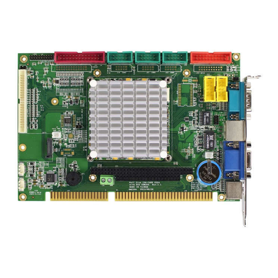
1 General Information 1.1 Overview The VDX3-6724 is a low-power CPU module which compliant with ISA standard. It takes the advantage of Vortex86DX3 1GHz x86 CPU which integrate the SATA, I2C, VGA, LVDS, PS/2, USB, HD Audio and even with 16-bit ISA bus support. -
Page 8: Specifications
2-pin box header for DC +5V output x1 15-pin D-Sub female connector for VGA x1 9-pin D-Sub male connector for RS232 x1 Type I/II Compact Flash slot x1 (Optional) Terminal block for DC input x1 PS/2 connector for Keyboard/Mouse x1 ICOP Technology Inc. - Page 9 -20°C to +70°C (Optional for Dual Core) Dimensions 184 x 122mm Weight 180g Windows 7 Linux Windows Embedded Compact 7 Windows XP Professional POS Ready (WePOS) O/S Support Windows Embedded Standard 7 Windows Embedded CE6.0 VxWorks Windows Embedded 2009 Free BSD ICOP Technology Inc.
-
Page 10: Ordering Information
Audio Line x2 NET 4x2 (2.0) x1 ICOP-0096 Vortex86 LVDS 18-bit Converter Kit for LCD Panel Display CABLE-LVDS-30 18-Bit LVDS Cable *Default setting for processor on VDX3-6724 is Single-core. If Dual-core processor is required, please contact ICOP (info@icop.com.tw). ICOP Technology Inc. - Page 11 VDX3-6724 User Manual Storages: Product Name 0°C to +70°C -40°C to +85°C SDM-SST-2G-H-M SDM-SST-4G-H-M ISATA-8G-H-M ISATA-16G-H-M ISATA-32G-H-M ISATA-4G-H-M-X ISATA-8G-H-M-X ISATA-16G-H-M-X ISATA-32G-H-M-X ISATA-1G-H-S ISATA-2G-H-S ISATA-4G-H-S ISATA-8G-H-S ISATA-16G-H-S SDM-SST-2G-H-S-X SDM-SST-4G-H-S-X SDM-SST-8G-H-S-X ISATA-16G-H-S-X Demonstration of “SDM-SST” SATA DoM on VDX3-6724 ICOP Technology Inc.
-
Page 12: Hardware Information
VDX3-6724 User Manual 2 Hardware Information 2.1 Board Dimension ICOP Technology Inc. -
Page 13: Board Outline
(optional) is selected. 3. GPIO will be occupied when eMMC is selected on VDX3-6724. 4. LPT, eMMC, and GPIO are not available on VDX3-6724-CF. 5. CF card slot is only available on VDX3-6724-CF. (see the image below) ICOP Technology Inc. - Page 14 VDX3-6724 User Manual VDX3-6724-CF TOP VIEW BOTTOM VIEW ICOP Technology Inc.
-
Page 15: Connector Summary
PC104 Connector – 40 pins Box Header, 2.54mm, 20x2 Line-Out Wafer, 1.25mm, 4x1 MIC-In Wafer, 1.25mm, 4x1 Touch screen Controller Wafer, 1.25mm, 4x1 (Optional) Parallel Box Header, 2.0mm, 13x2 Master/Slave for CF Card Slide switch CF card slot Buzzer ICOP Technology Inc. -
Page 16: Pin Assignments & Jumper Settings
VDX3-6724 User Manual 2.4 Pin Assignments & Jumper Settings J1: LCD Pin# Signal Name Pin # Signal Name +3.3V +3.3V LCLK LHSYNC LVSYNC LBACKL LVDDEN (Please refer to Appendix for TFT Flat Panel Data Output) ICOP Technology Inc. -
Page 17: J2: Vga
DDCCLK J3: LVDS (24-bit Support Only) Pin# Signal Name Pin # Signal Name VCC3 (+3.3V) VCC3 (+3.3V) RxIN0+ RxIN0- RxIN1- RxIN1+ RxIN2+ RxIN2- CKIN- CKIN+ RxIN3- GxIN3+ J4: SATA DOM Pin# Signal Name Pin # Signal Name ICOP Technology Inc. -
Page 18: J6: Sata Dom Power
Pin # Signal Name J10: LAN2 (10/100) Pin# Signal Name Pin # Signal Name ATX+ ATX- ARX+ LED0 LED0+ ARX- LED1+ LED1 J11: USB0&1 Pin# Signal Name Pin # Signal Name LUSBD0- LUSBD0- LUSBD0+ LUSBD1+ GGND GGND ICOP Technology Inc. -
Page 19: J12: Usb2&3
GP61 GP71 GP62 GP72 GP63 GP73 GP64 GP74 GP65 GP75 GP66 GP76 GP67 GP77 *When onboard eMMC is enabled, GPIO will be disabled. **Not available on VDX3-6724-CF J15: RESET Pin# Signal Name Pin # Signal Name RST_SW ICOP Technology Inc. -
Page 20: J17: Com1 Rs232/485 D-Sub 9 Pin
(Optional: TTL/ GPIO-P6) Pin# Signal Name Pin # Signal Name DCD5 RXD5 TXD5 DTR5 DSR5 RTS5 CTS5 J22: COM6 RS232 (Optional: TTL/ GPIO-P1) Pin# Signal Name Pin # Signal Name DCD6 RXD6 TXD6 DTR6 DSR6 RTS6 CTS6 ICOP Technology Inc. -
Page 21: J24A: Pc/104 Connector - 64 Pin
SMEMR* DRQ5 SA18 IOW* DACK6* SA17 IOR* DRQ6 SD10 SA16 DACK3* DACK7 SD11 SA15 DRQ3 DRQ7 SD12 SA14 DACK1* SD13 SA13 DRQ1* MASTER* SD14 SA12 REFRESH* SD15 SA11 SYSCLK SA10 IRQ7 IRQ6 IRQ5 IRQ4 IRQ3 DACK2* BALE ICOP Technology Inc. -
Page 22: J28: Line-Out
J28: Line-out J29: MIC-in Pin# Signal Name Pin# Signal Name LOUTR MICVREF LOUTL MIC-IN J30: Touch screen (Optional) Pin# Signal Name *Onboard SPI ROM (optional) and PS/2 Mouse will be disabled when Touch function (optional) is selected. ICOP Technology Inc. -
Page 23: J31: Parallel
VDX3-6724 User Manual J31: Parallel Pin# Signal Name Pin # Signal Name STB- AFD- ERR- INIT- SLIN- ACK- BUSY SLCT *Not available on VDX3-6724-CF ICOP Technology Inc. -
Page 24: System Mapping
000E0000 – 000EFFFF USB Legacy SCSI ROM space 000F0000 – 000FFFFF Motherboard BBIOS FEFDBC00 – FEFDBCFF Standard OpenHCD USB Host Controller FEFBB400 – FEFBB4FF Onboard Ethernet Adapter FEFDB800 – FEFDBFFF Standard Enhanced PCI to USB Host Controller ICOP Technology Inc. - Page 25 DMA High page register 0490h – 0499h Instruction counter register 04D0h – 04D1h 8259 Edge / level control register 0CF8h – 0CFFh PCI configuration port DE00h – DEFFh On board LAN FC00h – FC05h SPI Flash BIOS control register ICOP Technology Inc.
- Page 26 Real Timer Clock IRQ9 ACPI IRQ10 Serial Port 3 IRQ11 Serial Port 4 IRQ12 Mouse IRQ13 Math Coprocessor IRQ14 Multimedia Device IRQ15 Hard Disk Controller #2 DMA Mapping Address Description Usage DMA0 DMA1 DMA2 DMA3 DMA4 DMA5 DMA6 DMA7 ICOP Technology Inc.
-
Page 27: Software Resources
In the following website, you will find our latest user manuals, including OS support resources systems such as evaluation images for Windows Embedded Compact 7, Windows Embedded CE6.0, and Windows XP Embedded (Win XPe), etc. For details, please visit http://tech.icop.com.tw/. ICOP Technology Inc. -
Page 28: Basic Bios Setting
4 Basic BIOS Setting 4.1 Introduction Featuring AMI BIOS, the VDX3-6724 module is a one stable module board for your applications. In this section, we will introduce you some basic AMI BIOS setting such as CPU speed adjusting, console redirection, and IDE configuration, etc. -
Page 29: Serial Ports Switching
User Manual 4.4 Serial Ports Switching Serial ports on VDX3-6724 are set RS232 as default. If you need RS485 be your default serial ports. Please contact your contact window directly or mail info@icop.com.tw. And you can refer to the below instruction to select the IRQ mode according to your demands. -
Page 30: Ide Configuration
The default IDE configuration is for Windows Operating System, and the setting as below: Onboard IDE Operate Mode: [Legacy Mode] IDE Compatibility: [Disabled]. If you would like to use Linux on VDX3-6724, please follow below instructions: Onboard IDE Operate Mode: [Native Mode] IDE Compatibility: [Enabled]. -
Page 31: Advanced Pci-Pnp Setting
VDX3-6724 User Manual 4.6 Advanced PCI-PnP Setting Two statuses for IRQ setting: [Reserved]: IRQ will free to be allocated by PnP BIOS. [Available]: IRQ will not free to be allocated by PnP BIOS. Path: PCIPnP >IRQ ICOP Technology Inc. -
Page 32: Acpi Enable
VDX3-6724 User Manual 4.7 ACPI Enable To install Windows 7 on ICOP computer boards, please enable ACPI as the following instruction. Path: Advanced >Power Management Configuration > ACPI Configuration >ACPI Aware O/S ICOP Technology Inc. -
Page 33: Basic Lcd Panel Setting
User Manual 5 Basic LCD Panel Setting 5.1 Introduction The VDX3-6724 offers two different interfaces which support maximum resolution up to 1920 x 1080 (at 60 MHz) connecting to VGA and LCD Flat Panel with 18-bit/24bit LVDS(24-bit by default). The default setting of Boot Display Device [VBIOS] and LCD Panel Index [VBIOS] with Clone Display [ENBALED] support dual display (LCD and VGA) on VDX3-6724. -
Page 34: Pin Assignment Of Lvds
Resolution of the LCD Panel VBIOS the Required LCD Specification 640 x 480 800 x 480 800 x 600 1024 x 600 1024 x 768 Path of Boot Display Device setting: Boot >Boot Settings Configuration >Boot Display Device [VBIOS] ICOP Technology Inc. - Page 35 Path of LCD Panel Index setting: Boot >Boot Settings Configuration >LCD Panel Index [ ***The [VBIOS] difference between Boot Display Device and LCD Panel Index: Boot Display Device [VBIOS]: Display Output Setting LCD Panel Index [VBIOS]: Display Resolution Setting ICOP Technology Inc.
-
Page 36: Technical Support Directly From Icop
—Any complement or technical situations you want ICOP more focusing on User Manual Feedback To make this user manual more complete, if you have any comments or feedbacks to this manual, please feel free to write to info@icop.com.tw or contact your ICOP sales representative. ICOP Technology Inc. -
Page 37: Appendix
TFT Panel Data Output LCD Pin# Signal Name Digital 18 Bits RGB 24 Bits LCDVCC (+3.3) LCDVCC (+3.3) FPD12 FPD13 FPD14 FPD15 FPD16 FPD17 FPD18 FPD19 FPD20 FPD21 FPD22 FPD23 FPD0 FPD1 FPD2 FPD3 FPD4 FPD5 FPD6 FPD7 FPD8 FPD9 ICOP Technology Inc. - Page 38 VDX3-6724 User Manual LCD# Signal Name Digital 18 Bits RGB 24 Bits FPD10 FPD11 FP1CLK XCLK XCLK FP1DE FP1HS HSYNC HSYNC FP1VS VSYNC VSYNC FPENBLT FPENVDD VDDEN VDDEN ICOP Technology Inc.
-
Page 39: Stacking Solution For Daughter Board
Stacking Solution for Daughter Board 1. Please prepare PC104L40P x 1 and PC104L64P x 1 (as the image below shown). PC104L64P PC104L40P 2. Put on the nuts, pillars, screws and PC104 connector (as the image below shown) ICOP Technology Inc. - Page 40 VDX3-6724 User Manual 3. As the image below shown after stacking. Note: Please contact ICOP if the nuts, pillars and screws are required. ICOP Technology Inc.
-
Page 41: Warranty
Returned goods should always be accompanied by a clear problem description. Should you have questions about warranty and RMA service, please contact us directly. ICOP Technology Inc. Address: No. 15 Wugong 5th Road, Xinzhuang Dist. New Taipei City, Taiwan (R.O.C.) 24890...
Need help?
Do you have a question about the VDX3-6724 and is the answer not in the manual?
Questions and answers