Table of Contents
Advertisement
Quick Links
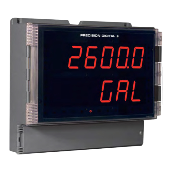
• Large 1.80" Digits
• Dual-Line 6-Digit Display
• Readable from up to 100 Feet (30 Meters) Away
• Superluminous Sunlight Readable Display
• NEMA 4X, IP65 Rated Field Mountable Enclosure
• Operating Temperature Range of -40 to 65°C (-40 to 150°F)
• 0-20 mA, 4-20 mA, 0-5 V, 1-5 V, and ±10 V Inputs
• Input Power Options Include 85-265 VAC or 12-24 VDC
• Isolated 24 VDC Transmitter Power Supply
• Signal Input Conditioning for Flow & Round Horizontal Tanks
• Programmable Display & Function Keys
• Multi-Pump Alternation Control
• 4 Relays + Isolated 4-20 mA Output Option
• Onboard USB & RS-485 Serial Communication
• Modbus
• Program the Meter from a PC with onboard USB and MeterView Pro
PRECISION DIGITAL CORPORATION
1.888.610.7664
Helios Large Display Analog Input Meter
Instruction Manual
®
RTU Communication Protocol Standard
www.calcert.com
15
10
20
5
25
0
30
PD2-6000
USB Install
Process
sales@calcert.com
Advertisement
Table of Contents

Subscribe to Our Youtube Channel
Related Manuals for Precision Digital Corporation PD2-6000


Summary of Contents for Precision Digital Corporation PD2-6000
- Page 1 • 4 Relays + Isolated 4-20 mA Output Option • Onboard USB & RS-485 Serial Communication • Modbus ® RTU Communication Protocol Standard • Program the Meter from a PC with onboard USB and MeterView Pro PRECISION DIGITAL CORPORATION 1.888.610.7664 www.calcert.com sales@calcert.com...
- Page 2 Limited Warranty Precision Digital Corporation warrants this product against defects in material or workmanship for the specified period under “Specifications” from the date of shipment from the factory. Precision Digital’s liability under this limited warranty shall not exceed the purchase value, repair, or replacement of the defective unit.
-
Page 3: Table Of Contents
PD2-6000 Helios Large Display Analog Input Meter Instruction Manual Table of Contents Table of Contents ............3 Relay and Alarm Operation Diagrams ......... 35 High Alarm Operation (Set > Reset) ....... 35 Table of Figures .............. 4 Low Alarm Operation (Set < Reset) ........ 35 Introduction .............. -
Page 4: Table Of Figures
A fully loaded Helios PD2-6000 meter comes with four (4) SPDT relays, a 4-20 mA output, two 24 VDC power supplies, five (5) digital inputs and four (4) digital outputs, and RS485 serial communications. -
Page 5: Specifications
PD2-6000 Helios Large Display Analog Input Meter Instruction Manual Specifications Except where noted all specifications apply to operation at +25°C. General Isolation 4 kV input/output-to-power line 500 V input-to-output or output-to-P+ Display Main display: 1.8" (46 mm) high, red supply... -
Page 6: Relays
Helios Large Display Analog Input Meter Instruction Manual PD2-6000 Time Delay 0 to 999.9 seconds, on & off relay time Round H Tank Diameter & Length: 999.999 inch or cm delays calculates volume in gallons or liters Programmable and independent for respectively. -
Page 7: Digital Input & Output Terminal
PD2-6000 Helios Large Display Analog Input Meter Instruction Manual Digital Input & Output Terminal Source Current 10 mA maximum output current Sink Current 1.5 mA minimum input current Channels 4 digital inputs & 4 digital outputs To be used as pull-up for digital inputs... -
Page 8: Safety Information
Helios Large Display Analog Input Meter Instruction Manual PD2-6000 Safety Information Caution: Read complete instructions Warning: Risk of electric shock or prior to installation and operation of the personal injury. meter. Hazardous voltages exist within enclosure. Installation and service should be performed only by trained service personnel. -
Page 9: Wall Mounting Instructions
PD2-6000 Helios Large Display Analog Input Meter Instruction Manual Wall Mounting Instructions The meter can be mounted to any wall using the four provided mounting holes. Note that the bottom mounting holes are located underneath the front door panel. To mount the meter to a wall, follow these instructions. -
Page 10: Pipe Mounting Instructions
Helios Large Display Analog Input Meter Instruction Manual PD2-6000 Pipe Mounting Instructions The meter can also be mounted to a pipe using the optional pipe mounting kit (PDA6260). This kit includes two mounting plates, two U-bolts, and the necessary nuts and bolts. To mount the meter to a pipe using the pipe mounting kit accessory, follow these instructions. -
Page 11: Transmitter Supply Voltage Selection (P+, P-)
PD2-6000 Helios Large Display Analog Input Meter Instruction Manual Transmitter Supply Voltage Selection (P+, P-) All meters, including models equipped with the 12-24 VDC power option, are shipped from the factory configured to provide 24 VDC power for the transmitter or sensor. -
Page 12: Connectors Labeling
MENU RESET ENT ER Figure 7. Connector Labeling for Fully Loaded PD2-6000 Power Connections Power connections are made to a two-terminal connector labeled POWER on Figure 7 on page 12. The meter will operate regardless of DC polarity connection. The + and - symbols are only a suggested wiring convention. -
Page 13: Signal Connections
PD2-6000 Helios Large Display Analog Input Meter Instruction Manual Signal Connections Signal connections are made to a six-terminal connector labeled SIGNAL on Figure 7. The COM (common) terminal is the return for the 4-20 mA and the 10 V input signals. -
Page 14: Modbus Rtu Serial Communications
Helios Large Display Analog Input Meter Instruction Manual PD2-6000 INPUT SIGNAL INPUT SIGNAL Signal 3-Wire Voltage Voltage Transducer Signal Figure 11. Voltage Input Connections The meter is capable of accepting any voltage from -10 VDC to +10 VDC. Modbus RTU Serial Communications Serial communications connection can be made to the onboard RS485 terminal block or USB connector shown in Figure 7. -
Page 15: Switching Inductive Loads
PD2-6000 Helios Large Display Analog Input Meter Instruction Manual Switching Inductive Loads The use of suppressors (snubbers) is strongly recommended when switching inductive loads to prevent disrupting the microprocessor’s operation. The suppressors also prolong the life of the relay contacts. -
Page 16: Rs485 Output Connections
Helios Large Display Analog Input Meter Instruction Manual PD2-6000 RS485 Output Connections An RS-485 connector is provided for the use of advanced Modbus ® serial communications. This connector converts the serial output of the meter to balanced, full or half-duplex RS-485 signals. It has a... -
Page 17: Figure 16. Rs-485 Two-Wire Multi-Drop Wiring
PD2-6000 Helios Large Display Analog Input Meter Instruction Manual Figure 16. RS-485 Two-Wire Multi-Drop Wiring Notes: 1. Termination resistors are optional, and values depend on the cable length and characteristic impedance. Consult the cable manufacturer for recommendations. 2. Refer to RS-232 to RS-485 Converter documentation for further details. -
Page 18: Digital I/O Connections
Helios Large Display Analog Input Meter Instruction Manual PD2-6000 Digital I/O Connections Digital inputs and outputs are provided in order to expand the functionality of the meter. Digital inputs are made via a push button or switch connection to the appropriate digital input connector block and the +5 VDC block. -
Page 19: 4-20 Ma Output Connections
PD2-6000 Helios Large Display Analog Input Meter Instruction Manual 4-20 mA Output Connections Connections for the 4-20 mA transmitter output are made to the connector terminals labeled MA OUT. The 4-20 mA output may be powered internally or from an external power supply. -
Page 20: Setup And Programming
Helios Large Display Analog Input Meter Instruction Manual PD2-6000 Setup and Programming The meter is factory calibrated prior to shipment to read in milliamps and volts depending on the input selection. The calibration equipment is certified to NIST standards. Overview There are no jumpers to set for the meter input selection. -
Page 21: Programming Buttons And Status Led Indicators
PD2-6000 Helios Large Display Analog Input Meter Instruction Manual Programming Buttons and Status LED Indicators The meter can be programmed using the buttons located behind the front door panel. Use the Menu button to enter or exit Programming Mode, the Up-Arrow button to cycle through menu options, and the Enter button to select the menu item or option you want. -
Page 22: Meterview ® Pro Software
Helios Large Display Analog Input Meter Instruction Manual PD2-6000 MeterView ® Pro Software The meter can also be programmed using the PC-based MeterView Pro software included with the meter. This software is can be installed on any Microsoft® Windows® (2000/XP/Vista/7/8/10) computer by connecting the meter’s onboard USB. -
Page 23: Display Functions & Messages
PD2-6000 Helios Large Display Analog Input Meter Instruction Manual Display Functions & Messages The meter displays various functions and messages during setup, programming, and operation. The following table shows the main menu functions and messages in the order they appear in the menu. - Page 24 Helios Large Display Analog Input Meter Instruction Manual PD2-6000 Display Parameter Action/Setting Description Fail-safe 1 Set relay 1 fail-safe operation FLS 1 Enable fail-safe operation Disable fail-safe operation Set relays 2-4 fail-safe operation Fail-safe 2 FLS 2 Enter relay Time Delay menu...
-
Page 25: Main Menu
PD2-6000 Helios Large Display Analog Input Meter Instruction Manual Main Menu The main menu consists of the most commonly used functions: Setup, Reset, Control, and Password. • Press Menu button to enter Programming Mode then press the Up arrow button to scroll main menu. -
Page 26: Setting Up The Meter (Setup)
Helios Large Display Analog Input Meter Instruction Manual PD2-6000 Setting up the Meter (setup) The Setup menu is used to select: 1. Input signal the meter will accept 2. Dual-scale feature for some level applications 3. Select the display units/tags 4. -
Page 27: Setting The Input Signal (Input)
PD2-6000 Helios Large Display Analog Input Meter Instruction Manual Setting the Input Signal (Input) Enter the Input menu to set up the meter to display current (mA) or voltage (volt) inputs. The current input is capable of accepting any signal from 0 to 20 mA. Select current input to accept 0-20 mA or 4-20 mA signals. -
Page 28: Setting The Decimal Point (Dec Pt)
Helios Large Display Analog Input Meter Instruction Manual PD2-6000 Setting the Decimal Point (dEc pt) The decimal point may be set with up to five decimal places or with no decimal point at all. Pressing the Right arrow moves the decimal point one place to the right until no decimal point is displayed, and then it moves to the leftmost position. -
Page 29: Programming The Meter (Prog)
Use the Calibrate menu to apply a signal from a calibrator or a flowmeter. • • The PD2-6000 is a single input meter with dual-scale capability. The Program menu contains the Scale and the Calibrate menus. Note: The Scale and Calibrate functions are exclusive of each other. The meter uses the last function programmed. - Page 30 Helios Large Display Analog Input Meter Instruction Manual PD2-6000 Scaling the Meter ( SCALE The process input (4-20 mA, 10 VDC) can be scaled to display the process variable in engineering units. A signal source is not needed to scale the meter; simply...
- Page 31 PD2-6000 Helios Large Display Analog Input Meter Instruction Manual Error Message (Error) An error message indicates that the calibration or scaling process was not successful. After the error message is displayed, the meter reverts to the input prior to the failure during calibration or scaling and to input 1 during internal calibration, allowing the appropriate input signal to be applied or programmed.
-
Page 32: Setting The Display Parameter & Intensity (Dsplay)
Helios Large Display Analog Input Meter Instruction Manual PD2-6000 Setting the Display Parameter & Intensity (dsplay) The main display (line 1) can be programmed to display: 1. Process value 1 (PV1) 2. Process value 2 (PV2) 3. Percent of PV1 (PCT) 4. -
Page 33: Setting The Relay Operation (Relay)
PD2-6000 Helios Large Display Analog Input Meter Instruction Manual Setting the Relay Operation (relay) This menu is used to set up the operation of the relays. During setup, the relays do not follow the input and they will remain in the state found prior to entering the Relay menu. -
Page 34: Setting The Relay Action
Helios Large Display Analog Input Meter Instruction Manual PD2-6000 Setting the Relay Action Operation of the relays is programmed in the Action menu. The relays may be set up for any of the following modes of operation: 1. Automatic reset (non-latching) 2. -
Page 35: Relay Action For Loss Of 4-20 Ma Input (Loop Break)
PD2-6000 Helios Large Display Analog Input Meter Instruction Manual Relay Action for Loss of 4-20 mA Input (Loop Break) The loop break feature is associated with the 4-20 mA input. Each relay may be programmed to go to one of the following conditions when the meter detects the loss of the input signal (i.e. < 0.005 mA): 1. -
Page 36: High Alarm With Fail-Safe Operation (Set > Reset)
Helios Large Display Analog Input Meter Instruction Manual PD2-6000 High Alarm with Fail-Safe Operation Low Alarm with Fail-Safe Operation (Set > Reset) (Set < Reset) Note: Relay coil is energized in non-alarm condition. Note: Relay coil is energized in non-alarm condition. -
Page 37: Relay Sampling Operation
PD2-6000 Helios Large Display Analog Input Meter Instruction Manual Relay Sampling Operation Input Reset Sample Sample Sample Time Time Time Relay When the signal crosses the set point, the relay trips and the sample time starts. After the sample time has elapsed, the relay resets. -
Page 38: Relay Operation Details
Helios Large Display Analog Input Meter Instruction Manual PD2-6000 Relay Operation Details Overview The relay capabilities of the meter expand its usefulness beyond simple indication to provide users with alarm and control functions. These capabilities include front panel alarm status LEDs as well as either 2 or 4 internal relays. -
Page 39: Latching And Non-Latching Relay Operation
PD2-6000 Helios Large Display Analog Input Meter Instruction Manual Latching and Non-Latching Relay Operation Relay terminology for following tables The relays can be set up for latching (manual reset) or non-latching (automatic reset) operation. Terminology Relay Condition Alarm (Tripped) The On and Off terminology does not refer to the status of Normal (Reset) the relay’s coil, which depends on the fail-safe mode... -
Page 40: Acknowledging Relays
Helios Large Display Analog Input Meter Instruction Manual PD2-6000 Acknowledging Relays There are two ways to acknowledge relays programmed for manual reset: 1. Via the programmable front panel function keys F1-F3 (Default: F3 assigned to ACK). 2. Remotely via a normally open pushbutton wired across one of the digital inputs and the +5 V terminals on the digital I/O terminal, or using the F4 digital input, which is triggered with a contact closure to COM, or with an active low signal (see page 18). - Page 41 PD2-6000 Helios Large Display Analog Input Meter Instruction Manual Application #2: Pump Alternation Using Relays 3 & 4 1. Relays 1 and 2 are set up for low Set and Reset Point Programming and high alarm indication. Relay Set Point...
-
Page 42: Setting Up The Interlock Relay (Force On) Feature
Helios Large Display Analog Input Meter Instruction Manual PD2-6000 Setting up the Interlock Relay (Force On) Feature Relays 1-4 can be set up as interlock relays. To set up the relays for the interlock feature: 1. Access the Setup – Relay – Action menu and set the action to off. -
Page 43: Scaling The 4-20 Ma Analog Output (Aout)
PD2-6000 Helios Large Display Analog Input Meter Instruction Manual Scaling the 4-20 mA Analog Output (Aout) The 4-20 mA analog output can be scaled to provide a 4-20 mA signal for any display range selected. No equipment is needed to scale the analog output; simply program the display values to the corresponding mA output signal. -
Page 44: Setting Up The Password (Pass)
Helios Large Display Analog Input Meter Instruction Manual PD2-6000 Setting up the Password (pass) The Password menu is used for programming three levels of security to prevent unauthorized changes to the programmed parameter settings. Pass 1: Allows use of function keys and digital inputs Pass 2: Allows use of function keys, digital inputs and editing set/reset points Pass 3: Restricts all programming, function keys, and digital inputs. -
Page 45: Making Changes To A Password Protected Meter
PD2-6000 Helios Large Display Analog Input Meter Instruction Manual Making Changes to a Password Protected Meter If the meter is password protected, the meter will display the message Locd (Locked) when the Menu button is pressed. Press the Enter button while the message is being displayed and enter the correct password to gain access to the menu. -
Page 46: Advanced Features Menu
Helios Large Display Analog Input Meter Instruction Manual PD2-6000 Advanced Features Menu To simplify the setup process, functions not needed for most applications are located in the Advanced Features menu. Press and hold the Menu button for three seconds to access the advanced features of the meter. - Page 47 PD2-6000 Helios Large Display Analog Input Meter Instruction Manual Display Parameter Action/Setting Set meter for square root extraction Square root Square Programmable Set meter for programmable exponent and enter exponent value Prog E exponent Set meter for round horizontal tank volume calculation...
-
Page 48: Noise Filter (Filter)
Helios Large Display Analog Input Meter Instruction Manual PD2-6000 Noise Filter (filter) The noise filter is available for unusually noisy signals that cause an unstable process variable display. The noise filter averages the input signal over a certain period. The filter level determines the length of time over which the signal is averaged. -
Page 49: Select Menu (Select)
PD2-6000 Helios Large Display Analog Input Meter Instruction Manual Select Menu (SElect) The Select menu is used to select the signal input conditioner applied to the input (linear, square root, programmable exponent, or round horizontal tank), low-flow cutoff, and analog output programming. The multi-point linearization is part of the linear function selection. - Page 50 Helios Large Display Analog Input Meter Instruction Manual PD2-6000 Multi-Point Linearization ( Linear Meters are set up at the factory for linear function with 2-point linearization. Up to 32 linearization points can be selected for PV1 under the linear function. The multi-point linearization can be used to linearize the display for non-linear signals such as those from level transmitters used to measure volume in odd- shaped tanks or to convert level to flow using weirs and flumes with complex exponent.
-
Page 51: Low-Flow Cutoff (Cutoff)
PD2-6000 Helios Large Display Analog Input Meter Instruction Manual Low-Flow Cutoff (CutofF) The low-flow cutoff feature allows the meter to be programmed so that the often-unsteady output from a differential pressure transmitter, at low flow rates, always displays zero on the meter. -
Page 52: Tare (Tare)
Helios Large Display Analog Input Meter Instruction Manual PD2-6000 Function Keys & Digital I/O Available Settings Refer to the following table for descriptions of each available function key or digital I/O setting. Display Description Display Description Display maximum & minimum... -
Page 53: Internal Source Calibration (Ical)
PD2-6000 Helios Large Display Analog Input Meter Instruction Manual Internal Source Calibration (ICAL) The meter is factory calibrated prior to shipment to read in milliamps and volts depending on the input selection. The calibration equipment is certified to NIST standards. -
Page 54: Meter Operation
Helios Large Display Analog Input Meter Instruction Manual PD2-6000 Meter Operation The meter is capable of accepting current (0-20 mA, 4-20 mA) and voltage signals (0-5 V, 1-5 V, 0-10 V, 10 V) and displaying these signals in engineering units from -99999 to 999999 (e.g. a 4-20 mA signal could be displayed as -50.000 to 50.000). -
Page 55: Maximum/Minimum Readings
PD2-6000 Helios Large Display Analog Input Meter Instruction Manual Maximum/Minimum Readings The max & min readings (peak & valley) reached by the process can be displayed either continuously or momentary: 1. Display briefly by assigning to the F1-F3 function keys or to the digital inputs in the User menu. -
Page 56: Troubleshooting
Helios Large Display Analog Input Meter Instruction Manual PD2-6000 Troubleshooting Due to the many features and functions of the meter, it’s possible that the setup of the meter does not agree with what an operator expects to see. If the meter is not working as expected, refer to the Diagnostics menu and recommendations below. -
Page 57: Factory Defaults & User Settings
PD2-6000 Helios Large Display Analog Input Meter Instruction Manual Factory Defaults & User Settings The following table shows the factory setting for most of the programmable parameters on the meter. Parameter Display Default Setting Parameter Display Default Setting Off delay relay 2 0.0 sec... -
Page 58: Troubleshooting Tips
Helios Large Display Analog Input Meter Instruction Manual PD2-6000 Parameter Display Default Setting Parameter Display Default Setting Digital output 1 Alarm 1 Password 1 000000 (unlocked) dO 1 Pass 1 Digital output 2 Alarm 2 Password 2 000000 (unlocked) dO 2...
Need help?
Do you have a question about the PD2-6000 and is the answer not in the manual?
Questions and answers