Table of Contents
Advertisement
Quick Links
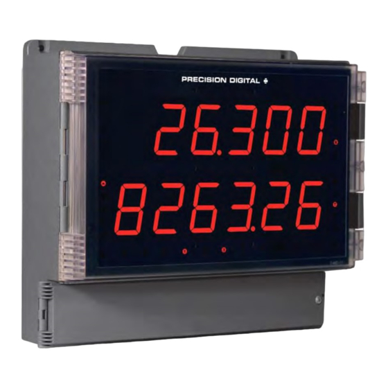
Helios Large Display Pulse Input Rate/Totalizer
Instruction Manual
• Large 1.80" Digits
• Dual-Line 6-Digit Display
• Readable from up to 100 Feet (30 Meters) Away
• Superluminous Sunlight Readable Display
• NEMA 4X, IP65 Rated Field Mountable Enclosure
• Operating Temperature Range of -40 to 65°C (-40 to 150°F)
• Pulse, Open Collector, NPN, PNP, TTL, Switch Contact,
Sine Wave (Coil), Square Wave Inputs
• Gate Function for Rate Display of Slow Pulse Rates
• Input Power Options Include 85-265 VAC or 12-24 VDC
• Isolated 24 VDC Transmitter Power Supply
• Rate Displayed as Units per Second, Minute, Hour, or Day
• 9-Digit Totalizer with Total Overflow Feature
• 2 or 4 Relays + Isolated 4-20 mA Output Options
• Onboard USB & RS-485 Serial Communications
• Modbus
• Program the Meter from a PC with onboard USB and MeterView Pro
Precision Digital Corporation
Find Quality Products Online at:
®
RTU Communication Protocol Standard
GlobalTestSupply
www.
PD2-6300
USB Install
Flow Rate/Totalizer
.com
sales@GlobalTestSupply.com
Advertisement
Table of Contents

Subscribe to Our Youtube Channel
Related Manuals for Precision Digital Corporation Helios PD2-6300-7H7


Summary of Contents for Precision Digital Corporation Helios PD2-6300-7H7
- Page 1 • 2 or 4 Relays + Isolated 4-20 mA Output Options • Onboard USB & RS-485 Serial Communications • Modbus ® RTU Communication Protocol Standard • Program the Meter from a PC with onboard USB and MeterView Pro Precision Digital Corporation GlobalTestSupply www. .com Find Quality Products Online at: sales@GlobalTestSupply.com...
- Page 2 Limited Warranty Precision Digital Corporation warrants this product against defects in material or workmanship for the specified period under “Specifications” from the date of shipment from the factory. Precision Digital’s liability under this limited warranty shall not exceed the purchase value, repair, or replacement of the defective unit.
-
Page 3: Table Of Contents
PD2-6300 Helios Large Display Pulse Input Rate/Totalizer Instruction Manual Table of Contents Table of Contents ............ 3 Programming Set and Reset Points ...... 35 Setting Fail-Safe Operation ........35 Table of Figures ............4 Programming Time Delay ........35 Introduction.............. 4 Relay and Alarm Operation Diagrams ....... -
Page 4: Table Of Figures
Helios Large Display Pulse Input Rate/Totalizer Instruction Manual PD2-6300 Table of Figures Figure 1. Meter Mounting Holes ......11 Figure 13: PNP Sensor Powered by Internal Supply Figure 2. Meter Dimensions - Side View ....11 ................15 Figure 3. Meter Dimensions – Front View .....11 Figure 14: Switch Input Connections .... -
Page 5: Ordering Information
PD2-6300 Helios Large Display Pulse Input Rate/Totalizer Instruction Manual Ordering Information Standard Models 85-265 VAC Model 12-24 VDC Model Options Installed PD2-6300-6H0 PD2-6300-7H0 No Options PD2-6300-6H7 PD2-6300-7H7 4 relays & 4-20 mA output Accessories Model Description PDA6260 Pipe Mounting Kit PDA7485-I RS-232 to RS-422/485 isolated converter PDA7485-N... -
Page 6: Rate Input
Helios Large Display Pulse Input Rate/Totalizer Instruction Manual PD2-6300 Isolation 4 kV input/output-to-power line Input Pulse input: Greater than 300 k @ 500 V input-to-output or output-to-P+ Impedance 1 kHz. supply Open collector/switch input: 4.7 k Overvoltage Installation Overvoltage Category II: pull-up to 5 V. -
Page 7: Relays
PD2-6300 Helios Large Display Pulse Input Rate/Totalizer Instruction Manual Relays Total Display 0 to 999,999; automatic lead zero & Total blanking. “T” LED is illuminated while Rating 2 or 4 SPDT (Form C) internal and/or Overflow displaying total or grand total. 4 SPST (Form A) external;... -
Page 8: Rs485 Serial Communications Terminal
Helios Large Display Pulse Input Rate/Totalizer Instruction Manual PD2-6300 Accuracy ± 0.1% of span ± 0.004 mA Parity Even, Odd, or None with 1 or 2 stop bits Temperature 0.4 µA/C max from 0 to 65C Drift Byte-To-Byte ambient, 0.01 – 2.54 second Timeout 0.8 µA/C max from -40 to 0C ambient... -
Page 9: Compliance Information
PD2-6300 Helios Large Display Pulse Input Rate/Totalizer Instruction Manual Compliance Information Safety UL & C-UL Listed USA & Canada UL 508 Industrial Control Equipment (United States), C22.2 No. 142 (Canadian National Standard) UL File Number E160849 Front Panel UL Type 4X, NEMA 4X, IP65 Low Voltage Directive EN 61010-1:2010 Safety requirements for measurement, control, and laboratory use... -
Page 10: Safety Information
Helios Large Display Pulse Input Rate/Totalizer Instruction Manual PD2-6300 Safety Information Caution: Read complete instructions Warning: Risk of electric shock or prior to installation and operation of the personal injury. meter. Hazardous voltages exist within enclosure. Installation and service should be performed only by trained service personnel. -
Page 11: Wall Mounting Instructions
PD2-6300 Helios Large Display Pulse Input Rate/Totalizer Instruction Manual Wall Mounting Instructions The meter can be mounted to any wall using the four provided mounting holes. Note that the bottom mounting holes are located underneath the front door panel. To mount the meter to a wall, follow these instructions. -
Page 12: Pipe Mounting Instructions
Helios Large Display Pulse Input Rate/Totalizer Instruction Manual PD2-6300 Pipe Mounting Instructions The meter can also be mounted to a pipe using the optional pipe mounting kit (PDA6260). This kit includes two mounting plates, two U-bolts, and the necessary nuts and bolts. To mount the meter to a pipe using the pipe mounting kit accessory, follow these instructions. -
Page 13: Transmitter Supply Voltage Selection (P+, P-)
PD2-6300 Helios Large Display Pulse Input Rate/Totalizer Instruction Manual Transmitter Supply Voltage Selection (P+, P-) All meters, including models equipped with the 12-24 VDC power option, are shipped from the factory configured to provide 24 VDC power for the transmitter or sensor. If the transmitter requires 5 or 10 VDC excitation, the switch labeled P+/P- must be configured accordingly. -
Page 14: Connectors Labeling
Helios Large Display Pulse Input Rate/Totalizer Instruction Manual PD2-6300 Connectors Labeling The connectors’ label, affixed to the inside of the lower door panel, shows the location of all connectors available with requested configuration. Do not connect any equipment other than Precision Digital’s expansion modules, cables, or meters to the RJ45 M-LINK connector. -
Page 15: Signal Connections
PD2-6300 Helios Large Display Pulse Input Rate/Totalizer Instruction Manual Signal Connections Signal connections are made to a six-terminal connector labeled SIGNAL on Figure 7. The COM (common) terminal is the return for the input signals. The following figures show examples of signal connections. Setup and programming is performed through the front panel buttons. -
Page 16: Switching Inductive Loads
Helios Large Display Pulse Input Rate/Totalizer Instruction Manual PD2-6300 Switching Inductive Loads The use of suppressors (snubbers) is strongly recommended when switching inductive loads to prevent disrupting the microprocessor’s operation. The suppressors also prolong the life of the relay contacts. Suppression can be obtained with resistor-capacitor (RC) networks assembled by the user or purchased as complete assemblies. -
Page 17: Rs485 Output Connections
PD2-6300 Helios Large Display Pulse Input Rate/Totalizer Instruction Manual RS485 Output Connections An RS-485 connector is provided for the use of advanced Modbus ® serial communications. This connector converts the serial output of the meter to balanced, full or half-duplex RS-485 signals. It has a removable screw terminal connector for the RS-485 terminals which includes Transmit Data (DO) and (/DO), Receive Data (DI) and (/DI), and Signal Ground. -
Page 18: Figure 19. Rs-485 Two-Wire Multi-Drop Wiring
Helios Large Display Pulse Input Rate/Totalizer Instruction Manual PD2-6300 Figure 19. RS-485 Two-Wire Multi-Drop Wiring Notes: 1. Termination resistors are optional and values depend on the cable length and characteristic impedance. Consult the cable manufacturer for recommendations. 2. Refer to RS-232 to RS-485 Converter documentation for further details. 3. -
Page 19: Digital I/O Connections
PD2-6300 Helios Large Display Pulse Input Rate/Totalizer Instruction Manual Digital I/O Connections Digital inputs and outputs are provides in order to expand the functionality of the meter. Digital inputs are made via a push button or switch connection to the appropriate digital input connector block and the +5 VDC block. -
Page 20: 4-20 Ma Output Connections
Helios Large Display Pulse Input Rate/Totalizer Instruction Manual PD2-6300 4-20 mA Output Connections Connections for the 4-20 mA transmitter output are made to the connector terminals labeled MA OUT. The 4-20 mA output may be powered internally or from an external power supply. Figure 24. -
Page 21: Setup And Programming
PD2-6300 Helios Large Display Pulse Input Rate/Totalizer Instruction Manual Setup and Programming • The meter has been factory calibrated to read input frequency in Hz (pulses/sec). The calibration equipment is certified to NIST standards. • Use the K-Factor menu to match the rate/totalizer with a flowmeter’s k-factor (pulse/unit of measure). -
Page 22: Programming Buttons And Status Led Indicators
Helios Large Display Pulse Input Rate/Totalizer Instruction Manual PD2-6300 Programming Buttons and Status LED Indicators The meter can be programmed using the buttons located behind the front door panel. Use the Menu button to enter or exit Programming Mode, the Up Arrow button to cycle through menu options, and the Enter button to select the menu item or option you want. -
Page 23: Meterview ® Pro Software
PD2-6300 Helios Large Display Pulse Input Rate/Totalizer Instruction Manual MeterView ® Pro Software The meter can also be programmed using the PC-based MeterView Pro software included with the meter. This software is can be installed on any Microsoft® Windows® (2000/XP/Vista/7/8/10) computer by connecting the meter’s onboard USB. -
Page 24: Display Functions & Messages
Helios Large Display Pulse Input Rate/Totalizer Instruction Manual PD2-6300 Display Functions & Messages The meter displays various functions and messages during setup, programming, and operation. The following table shows the main menu functions and messages in the order they appear in the menu. Display Parameter Action/Setting Description... - Page 25 PD2-6300 Helios Large Display Pulse Input Rate/Totalizer Instruction Manual Display Parameter Action/Setting Description Display intensity Set display intensity level from 1 to 8 d-Inty Enter the Relay menu Relay RELaY Assign relays to rate, total, or grand total Assignment Assign Relay 1 assignment Assign 1 Asign1...
- Page 26 Helios Large Display Pulse Input Rate/Totalizer Instruction Manual PD2-6300 Display Parameter Action/Setting Description Reset Press Enter to access the Reset menu reset Reset grand Press Enter to reset grand total Rst Gt total Press Enter to reset max display Reset high Rst Hi Press Enter to reset min display Reset low...
-
Page 27: Main Menu
PD2-6300 Helios Large Display Pulse Input Rate/Totalizer Instruction Manual Main Menu The main menu consists of the most commonly used functions: Setup, Reset, Control, and Password. • Press Menu button to enter Programming Mode then press the Up arrow button to scroll main menu. Press Menu, at any time, to exit and •... -
Page 28: Setting Up The Rate/Totalizer Meter (Setup)
Helios Large Display Pulse Input Rate/Totalizer Instruction Manual PD2-6300 Setting up the Rate/Totalizer Meter (setup) The Setup menu is used to select: 1. Enable or disable totalizer features 2. Units for Rate, Total, and Grand Total 3. Decimal point position 4. -
Page 29: Setting The Input Units Or Custom Tags (Units)
PD2-6300 Helios Large Display Pulse Input Rate/Totalizer Instruction Manual Setting the Input Units or Custom Tags (units) Enter the input unit or custom tag that will be displayed if d unit is selected as the little display parameter. See the flow chart on page 33 to access the display menu to show the unit or tag on the little display. -
Page 30: Programming The Rate/Totalizer (Prog)
Helios Large Display Pulse Input Rate/Totalizer Instruction Manual PD2-6300 Programming the Rate/Totalizer (prog) It is very important to read the following information, before proceeding to program the meter: • The meter has been factory calibrated to read input frequency in Hz (pulses/sec). The calibration equipment is certified to NIST standards. - Page 31 PD2-6300 Helios Large Display Pulse Input Rate/Totalizer Instruction Manual Scaling the Meter ( SCALE The process inputs (4-20 mA and 10 VDC) can be scaled to display the process variable in engineering units. A signal source is not needed to scale the meter; simply program the inputs and corresponding display values.
- Page 32 Helios Large Display Pulse Input Rate/Totalizer Instruction Manual PD2-6300 Time Base, Total Conversion Factor & Total Reset The time base, total conversion factor, and total reset menus are located in the Program menu. The total and grand total have their own independent settings. This means that one can be displaying the value in gallons while the other displays in million gallons, liters, m , etc.
-
Page 33: Setting The Display Parameter & Intensity (Dsplay)
PD2-6300 Helios Large Display Pulse Input Rate/Totalizer Instruction Manual Setting the Display Parameter & Intensity (dsplay) The main display (line 1) can be programmed to display: 1. Rate value 2. Total or grand total 3. Relay set points 4. Max & min values 5. -
Page 34: Setting The Relay Operation (Relay)
Helios Large Display Pulse Input Rate/Totalizer Instruction Manual PD2-6300 Setting the Relay Operation (relay) This menu is used to set up the operation of the relays. During setup, the relays do not follow the input and they will remain in the state found prior to entering the Relay menu. -
Page 35: Setting The Relay Action
PD2-6300 Helios Large Display Pulse Input Rate/Totalizer Instruction Manual Setting the Relay Action Operation of the relays is programmed in the Action menu. The relays may be set up for any of the following modes of operation: 1. Automatic reset (non-latching) 2. -
Page 36: Relay And Alarm Operation Diagrams
Helios Large Display Pulse Input Rate/Totalizer Instruction Manual PD2-6300 Relay and Alarm Operation Diagrams The following graphs illustrate the operation of the relays, status LEDs, and ACK button. High Alarm Operation (Set > Reset) Low Alarm Operation (Set < Reset) For Manual reset mode, ACK can be pressed For Manual reset mode, ACK can be pressed anytime to turn "off"... -
Page 37: High Alarm With Fail-Safe Operation (Set > Reset)37
PD2-6300 Helios Large Display Pulse Input Rate/Totalizer Instruction Manual High Alarm with Fail-Safe Operation Low Alarm with Fail-Safe Operation (Set > Reset) (Set < Reset) Note: Relay coil is energized in non-alarm condition. Note: Relay coil is energized in non-alarm condition. In case of power failure, relay will go to alarm In case of power failure, relay will go to alarm state. -
Page 38: Relay Sampling Operation
Helios Large Display Pulse Input Rate/Totalizer Instruction Manual PD2-6300 Relay Sampling Operation Input Reset Sample Sample Sample Time Time Time Relay When the signal crosses the set point, the relay trips and the sample time starts. After the sample time has elapsed, the relay resets. -
Page 39: Relay Operation Details
PD2-6300 Helios Large Display Pulse Input Rate/Totalizer Instruction Manual Relay Operation Details Overview The relay capabilities of the meter expand its usefulness beyond simple indication to provide users with alarm and control functions. These capabilities include front panel alarm status LEDs as well as either 2 or 4 internal relays. -
Page 40: Latching And Non-Latching Relay Operation
Helios Large Display Pulse Input Rate/Totalizer Instruction Manual PD2-6300 Latching and Non-Latching Relay Operation Relay terminology for following tables The relays can be set up for latching (manual reset) or non-latching (automatic reset) operation. Terminology Relay Condition Alarm (Tripped) The On and Off terminology does not refer to the status of Normal (Reset) the relay’s coil, which depends on the fail-safe mode Acknowledged... -
Page 41: Acknowledging Relays
PD2-6300 Helios Large Display Pulse Input Rate/Totalizer Instruction Manual Acknowledging Relays There are two ways to acknowledge relays programmed for manual reset: 1. Via the programmable front panel function keys F1-F3 (Default: F3 assigned to ACK). 2. Remotely via a normally open pushbutton wired across one of the digital inputs and the +5 V terminals on the digital I/O terminal, or using the F4 digital input, which is triggered with a contact closure to COM, or with an active low signal (see page 19). - Page 42 Helios Large Display Pulse Input Rate/Totalizer Instruction Manual PD2-6300 Application #2: Pump Alternation Using Relays 3 & 4 1. Relays 1 and 2 are set up for low Set and Reset Point Programming and high alarm indication. Relay Set Point Reset Point Function 2.
-
Page 43: Setting Up The Interlock Relay (Force On) Feature
PD2-6300 Helios Large Display Pulse Input Rate/Totalizer Instruction Manual Setting up the Interlock Relay (Force On) Feature Relays 1-4 can be set up as interlock relays. To set up the relays for the interlock feature: 1. Access the Setup – Relay – Action menu and set the action to off. 2. -
Page 44: Scaling The 4-20 Ma Analog Output (Aout)
Helios Large Display Pulse Input Rate/Totalizer Instruction Manual PD2-6300 Scaling the 4-20 mA Analog Output (Aout) The 4-20 mA analog output can be scaled to provide a 4-20 mA signal for any display range selected. No equipment is needed to scale the analog output; simply program the display values to the corresponding mA output signal. -
Page 45: Setting Up The Password (Pass)
PD2-6300 Helios Large Display Pulse Input Rate/Totalizer Instruction Manual Setting up the Password (pass) The Password menu is used for programming three levels of security to prevent unauthorized changes to the programmed parameter settings. Pass 1: Allows use of function keys and digital inputs Pass 2: Allows use of function keys, digital inputs and editing set/reset points Pass 3: Restricts all programming, function keys, and digital inputs Total: Prevents resetting the total manually... -
Page 46: Making Changes To A Password Protected Meter
Helios Large Display Pulse Input Rate/Totalizer Instruction Manual PD2-6300 Making Changes to a Password Protected Meter If the meter is password protected, the meter will display the message Locd (Locked) when the Menu button is pressed. Press the Enter button while the message is being displayed and enter the correct password to gain access to the menu. -
Page 47: Advanced Features Menu
PD2-6300 Helios Large Display Pulse Input Rate/Totalizer Instruction Manual Advanced Features Menu To simplify the setup process, functions not needed for most applications are located in the Advanced Features menu. Press and hold the Menu button for three seconds to access the advanced features of the meter. Advanced Features Menu &... - Page 48 Helios Large Display Pulse Input Rate/Totalizer Instruction Manual PD2-6300 Display Parameter Action/Setting Set low-flow cutoff Cutoff CutofF Set total and grand total count direction Count Count Total Count Set total to count up or down Tot C Grand Total Count Set grand total to count up or down Gtot C Program analog output parameters...
- Page 49 PD2-6300 Helios Large Display Pulse Input Rate/Totalizer Instruction Manual Low Gate (Lo G) For most applications, low gate setting should be left at 1.0 second. Increase low gate setting to obtain a steadier rate display. The rate display will update in accordance with the low gate setting, for example if low gate is set at 10.0, the display will update every 10 seconds;...
-
Page 50: Rounding Feature (Round)
Helios Large Display Pulse Input Rate/Totalizer Instruction Manual PD2-6300 Rounding Feature (round) The rounding feature is used to give the user a Rounding Actual Display Actual Display Selection Value Value Value Value steadier display with fluctuating signals. Rounding is used in addition to the filter function. 12.022 12.022 12.023... -
Page 51: Select Menu (Select)
PD2-6300 Helios Large Display Pulse Input Rate/Totalizer Instruction Manual Select Menu (SElect) The Select menu is used to select the signal input conditioner applied to the input (linear, square root, programmable exponent, or round horizontal tank), low-flow cutoff, and analog output programming. The multi-point linearization is part of the linear function selection. Signal Input Conditioning (Functn) The Function menu is used to select the linear input conditioner applied to the input signal. -
Page 52: Low-Flow Cutoff (Cutoff)
Helios Large Display Pulse Input Rate/Totalizer Instruction Manual PD2-6300 Low-Flow Cutoff (CutofF) The low-flow cutoff feature allows the meter to be programmed so that the often-unsteady output from a differential pressure transmitter, at low flow rates, always displays zero on the meter. The cutoff value may be programmed from 0 to 999999. - Page 53 PD2-6300 Helios Large Display Pulse Input Rate/Totalizer Instruction Manual Function Keys & Digital I/O Available Settings Refer to the following table for descriptions of each available function key or digital I/O setting. Display Description Display Description Directly access the control menu Directly access the relay menu Contrl relay...
-
Page 54: Meter Operation
Helios Large Display Pulse Input Rate/Totalizer Instruction Manual PD2-6300 Meter Operation The meter accepts pulses (e.g. ±40mV to ± 8V), square wave (0-5, 0-12V, or 0-24V), open collector NPN, PNP, TTL, or switch contact signals and displays these signals in engineering units from -99999 to 999999. -
Page 55: Maximum/Minimum Readings
PD2-6300 Helios Large Display Pulse Input Rate/Totalizer Instruction Manual Maximum/Minimum Readings The max & min readings (peak & valley) reached by the process can be displayed either continuously or momentary: 1. Display briefly by assigning to the F1-F3 function keys or to the digital inputs in the User menu. 2. -
Page 56: Determining Software Version
Helios Large Display Pulse Input Rate/Totalizer Instruction Manual PD2-6300 Determining Software Version To determine the software version of a meter: 1. Go to the Diagnostics menu (diAG) and press Enter button. 2. Press Up arrow button and scroll to Information menu (Info). 3. -
Page 57: Factory Defaults & User Settings
PD2-6300 Helios Large Display Pulse Input Rate/Totalizer Instruction Manual Factory Defaults & User Settings The following table shows the factory setting for most of the programmable parameters on the meter. Parameter Display Default Setting Parameter Display Default Setting Relay 1 Input type Pulse Input... - Page 58 Helios Large Display Pulse Input Rate/Totalizer Instruction Manual PD2-6300 Parameter Display Default Setting Parameter Display Default Setting On delay Baud rate 9600 baud 0.0 sec On 1 relay 1 Transmit 50 ms Tr dly Off delay delay 0.0 sec Off 1 relay 1 Parity Even...
-
Page 59: Troubleshooting Tips
PD2-6300 Helios Large Display Pulse Input Rate/Totalizer Instruction Manual Troubleshooting Tips Symptom Check/Action No display at all Check power at power connector Not able to change setup or Meter is password-protected, enter correct six-digit password to programming, Locd is displayed unlock Meter displays error message Check:...
Need help?
Do you have a question about the Helios PD2-6300-7H7 and is the answer not in the manual?
Questions and answers