Table of Contents
Advertisement
Quick Links
•
Accepts Current, Voltage, TC, & RTD Inputs
•
4 Digit Display, 0.56" (14 mm) or 1.20" (31 mm)
•
Linear or Square Root with Low-Flow Cutoff
•
Operating temperature range of between -40°C and 65°C
•
Maximum/Minimum Display
•
Type 4X, NEMA 4X, IP65 Front
•
Universal Power Supply 85-265 VAC
•
12-36 VDC/12-24 VAC Power Option
•
Two Relays and 4-20 mA Output Option
•
24 VDC Transmitter Power Supply Options
•
USB, RS-232, & RS-485
Serial Communication Adapters Options
•
Free Modbus
•
Copy Meter Settings to Other Meters
•
Free MeterView
800.561.8187
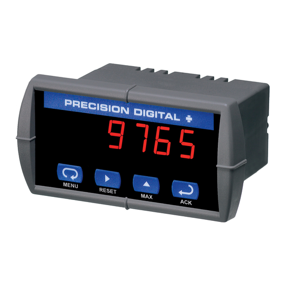
TRIDENT & TRIDENT X2
MODEL PD765
Instruction Manual
®
RTU Protocol
®
Software - Configuration & Data Acquisition
www.
information@itm.com
.com
Advertisement
Table of Contents
Troubleshooting

Related Manuals for Precision Digital Corporation TRIDENT


Summary of Contents for Precision Digital Corporation TRIDENT
- Page 1 TRIDENT & TRIDENT X2 MODEL PD765 Instruction Manual • Accepts Current, Voltage, TC, & RTD Inputs • 4 Digit Display, 0.56" (14 mm) or 1.20" (31 mm) • Linear or Square Root with Low-Flow Cutoff • Operating temperature range of between -40°C and 65°C •...
-
Page 2: Introduction
© 2011-2016 Precision Digital Corporation. All rights reserved. INTRODUCTION The Trident is a multipurpose, easy to use digital panel meter. It accepts current, voltage, thermocouple, and RTD signals. The four front panel buttons make the setup and programming an easy task. -
Page 3: Ordering Information
2 relays, 4-20 mA output, & 24 V supply Accessories Model Description PDA7232 RS-232 serial adapter with PDA7420 included PDA7420 Trident meter copy cable, 7' (2.1 m) PDA7422 RS-485 serial adapter with PDA7420 included PDA7485-I RS-232 to RS-485 isolated converter PDA7485-N RS-232 to RS-485 non-isolated converter... -
Page 4: Table Of Contents
Trident Model PD765 Universal Input Meter Instruction Manual Table of Contents INTRODUCTION ------------------------------------------------------------ 2 ORDERING INFORMATION --------------------------------------------- 3 SPECIFICATIONS ---------------------------------------------------------- 7 General ------------------------------------------------------------------------------- 7 Process Input ---------------------------------------------------------------------- 8 Temperature Inputs -------------------------------------------------------------- 9 Relays Option -------------------------------------------------------------------- 10 Isolated 4-20 mA Transmitter Output ------------------------------------ 11... - Page 5 Trident Model PD765 Universal Input Meter Instruction Manual Recalibrating Process Inputs (ICal) ------------------------------------- 36 Setting the Relay Operation (rely) -------------------------------------- 37 Relay and Alarm Operation ------------------------------------------------ 41 Pump Alternation Control Operation ------------------------------------- 46 Scaling the 4-20 mA Analog Output (Aout) ---------------------------- 47...
- Page 6 Trident Model PD765 Universal Input Meter Instruction Manual Table of Figures Figure 1. Panel Cutout and Mounting ..........14 Figure 2. Labeling for 2 Relay, Analog Out, & 24 V Supply Model . 15 Figure 3. Labeling for Analog Out & Two 24 V Supply Model ..15 Figure 4.
-
Page 7: Specifications
Instruction Manual SPECIFICATIONS Except where noted all specifications apply to operation at +25°C. General DISPLAY Trident: 0.56" (14 mm), Trident X2: 1.20" (31 mm), Four digits (-1999 to 9999), automatic lead zero blanking. DISPLAY INTENSITY Eight intensity levels DISPLAY Process/RTD: 3.7-5/second UPDATE RATE Thermocouple: 1.8-2.5/second... -
Page 8: Process Input
Trident Model PD765 Universal Input Meter Instruction Manual ENVIRONMENTAL Operating temperature range: -40 to 65°C Storage temperature range: -40 to 85°C Relative humidity: 0 to 90% non-condensing CONNECTIONS Removable screw terminal blocks accept 12 to 22 AWG wire, RJ11 for serial communication adapters... -
Page 9: Temperature Inputs
Trident Model PD765 Universal Input Meter Instruction Manual Temperature Inputs INPUTS Field selectable: type J, K, T, or E thermocouples; 100 Ω platinum RTD (0.00385 or 0.00392 curve) RESOLUTION 1° or 0.1° for all RTD inputs. 1° for all thermocouples. -
Page 10: Relays Option
Trident Model PD765 Universal Input Meter Instruction Manual Relays Option RATING 2 SPDT (Form C); rated 3 A @ 30 VDC or 3 A @ 250 VAC resistive load; 1/14 HP @ 125/250 VAC (50 watts) for induc- tive loads... -
Page 11: Isolated 4-20 Ma Transmitter Output
Trident Model PD765 Universal Input Meter Instruction Manual Isolated 4-20 mA Transmitter Output OUTPUT RANGE 1.00 to 23.00 mA typical CALIBRATION Factory calibrated for 4-20 mA SCALING RANGE 0.00 to 23.99 mA for any display range, see output range above ACCURACY ±... -
Page 12: Compliance Information
Trident Model PD765 Universal Input Meter Instruction Manual COMPLIANCE INFORMATION Safety UL LISTED USA and Canada UL 508 Industrial Control Equipment UL FILE NUMBER E160849 FRONT PANEL UL Type 4X, NEMA 4X, IP65; panel gasket provided LOW VOLTAGE EN 61010-1:2010... -
Page 13: Safety Information
Trident Model PD765 Universal Input Meter Instruction Manual Note: Testing was conducted on Trident Meters installed through the co- vers of grounded metal enclosures with cable shields grounded at the point of entry representing installations designed to optimize EMC performance. -
Page 14: Installation
Trident Model PD765 Universal Input Meter Instruction Manual INSTALLATION There is no need to remove the meter from its case to com- plete the installation, wiring, and setup of the meter. Unpacking Remove the meter from box. Inspect the packaging and con- tents for damage. -
Page 15: Connections
Trident Model PD765 Universal Input Meter Instruction Manual Connections All connections are made to removable screw terminal connectors located at the rear of the meter. Use copper wire with 60°C or 60/75°C insulation for all line voltage connections. Observe all safety regulations. -
Page 16: Power Connections
Trident Model PD765 Universal Input Meter Instruction Manual Power Connections Power connections are made to a two-terminal connector labeled POWER on Figure 2. The meter will operate regardless of DC polarity connection. The + and - symbols are only a suggested wiring convention. - Page 17 Trident Model PD765 Universal Input Meter Instruction Manual Figure 6. Transmitters Powered by Internal Supply (Optional) The current input is protected against current overload by a resettable fuse. The display may or may not show a fault condition depending on the nature of the overload.
- Page 18 Trident Model PD765 Universal Input Meter Instruction Manual Thermocouple and RTD Connections The following figures show examples for thermocouple and RTD con- nections. The RTD/TC selector switch must be set to the proper position for the meter to accept the selected temperature input.
- Page 19 Trident Model PD765 Universal Input Meter Instruction Manual Figure 10. Two-Wire RTD Input Connections Lead wire compensation for two-wire RTDs can be applied using the Adjust menu. See Offset Adjustment (Adj), page 53. Figure 11. Four-Wire RTD Input Connections The four-wire RTD connection is similar to the three-wire. One of the leads of a four-wire RTD is not connected, and may be clipped off.
-
Page 20: Serial Communication
Trident Model PD765 Universal Input Meter Instruction Manual Serial Communication Serial communication connection is made to an RJ11 connector labeled SERIAL on Figure 2. Use PDA7232 for RS-232 interfacing. Use PDA7422 for RS-485 interfacing. Use PDA7420 for meter-to-meter interfacing for cloning purposes (i.e. - Page 21 Trident Model PD765 Universal Input Meter Instruction Manual Choose R and C as follows: R: 0.5 to 1 Ω for each volt across the contacts C: 0.5 to 1 µF for each amp through closed contacts Notes: Inductive relay rating is 1/14 HP (50 W) at 115/230 VAC Use capacitors rated for 250 VAC.
-
Page 22: 4-20 Ma Output & Input Signal Connections
Trident Model PD765 Universal Input Meter Instruction Manual 4-20 mA Output & Input Signal Connections Connections for the 4-20 mA transmitter output are made to the con- nector terminals labeled “mA OUT, I-, I+”. The 4-20 mA output may be powered from an internal power supply (optional) or from an external power supply. -
Page 23: Setup And Programming
Trident Model PD765 Universal Input Meter Instruction Manual SETUP AND PROGRAMMING ® Programming From a PC with MeterView ® Precision Digital’s free MeterView software allows all PD765 Trident setup parameters to be programmed from a PC (requires PDC protocol selection) and to save the configuration settings to a file for reporting or programming other meters. -
Page 24: Front Panel Buttons And Status Led Indicators
Trident Model PD765 Universal Input Meter Instruction Manual Front Panel Buttons and Status LED Indicators Button Description Status Symbol Menu Alarm 1 Right arrow/Reset Alarm 2 Up arrow/Max Set point indicator Enter/Ack Reset point indicator • Press the Menu button to enter or exit the Programming Mode at any time. -
Page 25: Display Functions And Messages
Trident Model PD765 Universal Input Meter Instruction Manual Display Functions and Messages The meter displays various functions and messages during setup/pro- gramming and operation. The following table shows the displayed func- tions and messages with their action/setting description. Display Parameter... - Page 26 Trident Model PD765 Universal Input Meter Instruction Manual Display Parameter Action/Setting Display 2 Program display 2 value dis2 Error Error, calibration not successful, check signal Relay Enter the Relay menu RELY RLY1 Relay 1 Relay 1 setup Set relay 1 action (automatic, latching, etc.)
- Page 27 Trident Model PD765 Universal Input Meter Instruction Manual Display Parameter Action/Setting On 2 Set relay 2 On time delay Off 2 Set relay 2 Off time delay OFF2 Break Set RTD/TC input break relay behavior brek Brk1 Relay 1 Break...
-
Page 28: Main Menu
Trident Model PD765 Universal Input Meter Instruction Manual Main Menu The main menu consists of the most commonly used functions: Setup and Password . • Press Menu button to enter Programming Mode then press Up ar- row button to scroll main menu. -
Page 29: Setting Up The Meter (Setu)
Trident Model PD765 Universal Input Meter Instruction Manual Setting Up the Meter (setu) The Setup menu is used to select: Input signal the meter will accept Decimal point position for process inputs Units ( ° F or ° C) for temperature inputs... -
Page 30: Setting The Input Signal (Inpt)
Trident Model PD765 Universal Input Meter Instruction Manual Setting the Input Signal (inpt) Enter the Input menu to set up the meter to display current (4-20), volt- age (0-10), thermocouple (tC), or RTD (rtd) inputs. The voltage input is capable of accepting any signal from -10 to +10 VDC. -
Page 31: Setting The Decimal Point (Dc. P T)
Trident Model PD765 Universal Input Meter Instruction Manual Setting the Decimal Point (dc. p t) Decimal point for process inputs may be set with up to three decimal places or with no decimal point at all. Decimal point for RTD inputs may be set with 1 decimal place or none. -
Page 32: Programming The Meter (Prog)
Trident Model PD765 Universal Input Meter Instruction Manual Programming the Meter (prog) It is very important to read the following information, before proceeding to program the meter: • There is no need to recalibrate the meter when first received from the factory. -
Page 33: Scaling The Meter (Scal)
Trident Model PD765 Universal Input Meter Instruction Manual Scaling the Meter (scal) The process inputs (4-20 mA and ±10 VDC) can be scaled to display the process in engineering units. A signal source is not needed to scale the meter; simply program the in- puts and corresponding display values. - Page 34 Trident Model PD765 Universal Input Meter Instruction Manual Error Message (Err) An error message indicates that the calibration or scaling process was not successful. After the error message is displayed, the meter reverts to input 1, allow- ing the appropriate input signals to be applied.
-
Page 35: Calibrating The Meter (Cal)
Trident Model PD765 Universal Input Meter Instruction Manual Calibrating the Meter (Cal) To scale the meter without a signal source, refer to Scaling the Meter (scal), page 33. The meter can be calibrated to display the process in engineering units by applying the appropriate input signal and following the calibration procedure. -
Page 36: Recalibrating Process Inputs (Ical)
Trident Model PD765 Universal Input Meter Instruction Manual Recommended Calibration Points To recalibrate the meter, it is recommended to use the Fahrenheit scale; this will give a greater degree of accuracy to the calibration. The scale can be changed to the Celsius scale after calibration is completed. The meter will display temperature accurately in any scale. -
Page 37: Setting The Relay Operation (Rely)
Trident Model PD765 Universal Input Meter Instruction Manual Setting the Relay Operation (rely) This menu allows you to set up the operation of the relays: Relay action Automatic reset only (non-latching) Automatic + manual reset at any time (non-latching) Latching (manual reset only) - Page 38 Trident Model PD765 Universal Input Meter Instruction Manual Setting the Relay Action The relays’ Action menu allows the user to set up the operation of the relays. The relays may be set up for any of the following modes of oper-...
- Page 39 Trident Model PD765 Universal Input Meter Instruction Manual Setting Fail-Safe Operation The fail-safe operation is set independently for each relay. Select on to enable or select off to disable fail-safe operation. FLSF Press Enter/Ack button to accept setting Press Menu button to exit at any time...
- Page 40 Trident Model PD765 Universal Input Meter Instruction Manual Setting Sensor Break Condition The sensor break relay condition may be programmed for each relay as On (alarm) or Off (non-alarm). The relays will enter these states when a sensor break is detected for RTD or thermocouple inputs. These set- tings have no effect when current or voltage inputs are selected.
-
Page 41: Relay And Alarm Operation
Trident Model PD765 Universal Input Meter Instruction Manual Relay and Alarm Operation The following graphs illustrate the operation of the relays, status LEDs, and ACK button. High Alarm Operation (Set > Reset) For Manual reset mode, ACK can be pressed anytime to turn "off" relay. - Page 42 Trident Model PD765 Universal Input Meter Instruction Manual Low Alarm Operation (Set < Reset) For Manual reset mode, ACK can be pressed anytime to turn "off" relay. For relay to turn back "on", signal must go above set point, and then go below it.
- Page 43 Trident Model PD765 Universal Input Meter Instruction Manual Time Delay Operation The following graphs show the operation of the time delay function. If the signal crosses the set point, the On time delay timer starts and the relay trips when the time delay has elapsed. If the signal drops below the set point (high alarm) before the time delay has elapsed, the On time delay timer resets and the relay does not change state.
- Page 44 Trident Model PD765 Universal Input Meter Instruction Manual High Alarm with Fail-Safe Operation (Set > Reset) Fail-safe operation: relay coil is energized in non-alarm condition. In case of power failure, relay will go to alarm state. 800.561.8187 information@itm.com www. .com...
- Page 45 Trident Model PD765 Universal Input Meter Instruction Manual Low Alarm with Fail-Safe Operation (Set < Reset) Fail-safe operation: relay coil is energized in non-alarm condition. In case of power failure, relay will go to alarm state. 800.561.8187 information@itm.com www. .com...
-
Page 46: Pump Alternation Control Operation
Trident Model PD765 Universal Input Meter Instruction Manual 800.561.8187 information@itm.com www. .com... -
Page 47: Scaling The 4-20 Ma Analog Output (Aout)
Trident Model PD765 Universal Input Meter Instruction Manual Scaling the 4-20 mA Analog Output (Aout) The 4-20 mA analog output can be scaled to provide a 4-20 mA signal for any display range selected. No equipment is needed to scale the analog output; simply program the display values to the corresponding mA output signal. -
Page 48: Program The Sensor Break Output Value (Sebr)
Trident Model PD765 Universal Input Meter Instruction Manual Program the Sensor Break Output Value (SEbr) The sensor break value corresponds to the output signal generated when the meter detects a sensor break for thermocouple and RTD in- puts. For example if there is an open thermocouple, the meter displays the message “... -
Page 49: Setting Up The Password (Pass)
Trident Model PD765 Universal Input Meter Instruction Manual Setting Up the Password (pass) The Password menu is used to program a four-digit password to pre- vent unauthorized changes to the programmed parameter settings. Locking the Meter Enter the Password menu and program a four-digit password. -
Page 50: Advanced Features Menu
Trident Model PD765 Universal Input Meter Instruction Manual Entering the correct four-digit number sets the password to 0000, disa- bling the protection. Changes to the programmed parameter settings are allowed only with the password set to 0000. If the password entered is incorrect, the meter displays LoCd (Locked) for about two seconds, then it returns to Run Mode. -
Page 51: Advanced Features Menu & Display Messages
Trident Model PD765 Universal Input Meter Instruction Manual Advanced Features Menu & Display Messages Display Parameter Action/Setting Adjust Set offset adjustment for temperature, not available for process inputs Set noise filter value fltr Filter Set filter bypass value byps Bypass... - Page 52 Trident Model PD765 Universal Input Meter Instruction Manual Display Parameter Action/Setting Enter initial calibration for process inputs ICal Initial calibration Current Calibrating current input Curr I low Calibrate low current input I lo I high Calibrate high current input I Hi...
-
Page 53: Offset Adjustment (Adj)
Trident Model PD765 Universal Input Meter Instruction Manual Offset Adjustment (Adj) This parameter allows the user to select an offset adjustment to the temperature being displayed. Offset adjustment values can be either positive or negative and can be any number within ± 19.9 ° . The offset adjustment value is programmed through the Adjust menu. -
Page 54: Noise Filter Bypass (Byps)
The transmit delay may be set between 0 and 199 ms (see Se- rial Communication Adapter manual for more details). The Trident can also be connected directly to another Trident meter through a cable assembly (PDA7420). This allows the user to copy all the settings from one meter to another, using the Copy function. -
Page 55: Select Menu (Selc)
Trident Model PD765 Universal Input Meter Instruction Manual Select Menu (SElc) The Select menu is used to select linear or square root function, display intensity, and low-flow cutoff. Selection for relay or analog output is a factory setting depending on the option installed. -
Page 56: Low-Flow Cutoff (Cutf)
Trident Model PD765 Universal Input Meter Instruction Manual Low-Flow Cutoff (cutF) The low-flow cutoff feature allows the meter to be programmed so that the often-unsteady output from a differential pressure transmitter, at low flow rates, always displays zero on the meter. -
Page 57: Meter Copy Function (Copy)
® MeterView Software ® Precision Digital’s MeterView software allows the Trident to be pro- grammed from a PC and to act as a data logger. ® MeterView software allows all setup parameters to be saved to a file for reporting, restoring, or programming other meters. - Page 58 Trident Model PD765 Universal Input Meter Instruction Manual Meter Cloning Instructions NOTICE! Do not connect the two meters to the same 4-20 mA loop while cloning. Internal calibration may be affected. Connect the two meters using cable assembly PDA7420 or equiva- lent ( e.g.
-
Page 59: Internal Calibration (Ical)
Trident Model PD765 Universal Input Meter Instruction Manual Internal Calibration (ICal) • There is no need to recalibrate the meter when first received from the factory. • The meter is factory calibrated prior to shipment, for all input types, in milliamps, volts, and degrees respectively. - Page 60 Trident Model PD765 Universal Input Meter Instruction Manual Example for current input internal calibration: The meter displays Low input current ( I lo ). Apply the low input signal and press Enter/Ack . The display flashes for a moment while meter is accepting the low input.
- Page 61 Trident Model PD765 Universal Input Meter Instruction Manual Tips: • Low and high input signals can be any valid values within the range of the meter. • Observe minimum input span requirements between input 1 and input 2. • Low input must be less than high input signal.
-
Page 62: Operation
Trident Model PD765 Universal Input Meter Instruction Manual OPERATION For process inputs, the meter is capable of accepting positive and nega- tive signals and displaying these signals in engineering units from -1999 to 9999 ( e.g. a signal from -10 to +10 VDC could be displayed as -10.00 to 10.00). -
Page 63: Maximum/Minimum Readings
Trident Model PD765 Universal Input Meter Instruction Manual Maximum/Minimum Readings The main function of the front panel buttons during operation is to dis- play the maximum and minimum readings reached by the process or temperature inputs. Actual Reading 2468 9846... -
Page 64: Mounting Dimensions
Trident Model PD765 Universal Input Meter Instruction Manual MOUNTING DIMENSIONS 1.76" (45mm) 2.45" (62mm) 3.2" 0.59" (81mm) (15mm) 3.6" (91mm) Figure 18. Meter Dimensions – Side View Figure 19. Case Dimensions – Top View 800.561.8187 information@itm.com www. .com... -
Page 65: Troubleshooting
Trident Model PD765 Universal Input Meter Instruction Manual TROUBLESHOOTING For an Interactive Virtual Meter Demo visit tvm.predig.com Due to the many features and functions of the meter, it’s possible that the setup of the meter does not agree with what an operator expects to see. -
Page 66: Reset Meter To Factory Defaults
Trident Model PD765 Universal Input Meter Instruction Manual Reset Meter to Factory Defaults When the parameters have been changed in a way that is difficult to de- termine what’s happening, it might be better to start the setup process from the factory defaults. -
Page 67: Factory Defaults & User Settings
Trident Model PD765 Universal Input Meter Instruction Manual Factory Defaults & User Settings The following table shows the factory setting for most of the program- mable parameters on the meter. Next to the factory setting, the user ® may record the new setting for the particular application. MeterView software allows the saving of all meter parameters to a file for restoring meter settings, reporting, and copying settings to other meters. - Page 68 Trident Model PD765 Universal Input Meter Instruction Manual Parameter Display Default Setting User Setting On delay 2 0 sec Off delay 2 0 sec Off2 Break 1 Brk1 Break 2 Brk2 Password 0000 (unlocked) pass Advanced Features Adjust 0.0 ° (temp only)
-
Page 69: Troubleshooting Tips
Trident Model PD765 Universal Input Meter Instruction Manual Troubleshooting Tips Symptom Check/Action Check power at power connector No display at all Meter is locked, enter correct four-digit Not able to change setup or pro- password to unlock gramming, LoCd is displayed... -
Page 70: Quick Interface Reference Guide
Trident Model PD765 Universal Input Meter Instruction Manual QUICK INTERFACE REFERENCE GUIDE Run Mode A385 4-20 mA Input Display A392 Max/Min 0-10 V Setup Type J Type K Password Type T Type T.0 Locked Unlocked Type E TC or RTD? - Page 71 Trident Model PD765 Universal Input Meter Instruction Manual Pushbutton Function Menu Go to Programming Mode or leave Programming, Advanced Features, and Max/Min Modes. Right Arrow Move to next digit. Up Arrow Move to next selection or increment digit. Enter/Ack Accept selection/value and move to next selection.
Need help?
Do you have a question about the TRIDENT and is the answer not in the manual?
Questions and answers