Table of Contents
Advertisement
Quick Links
Copyright
Copyright © 2021 MiTAC International Corporation. All rights reserved. No part of
this manual may be reproduced or translated without prior written consent from
MiTAC International Corporation.
Trademark
All registered and unregistered trademarks and company names contained in this
manual are property of their respective owners including, but not limited to the
following.
®
TYAN
is a trademark of MiTAC International Corporation.
®
Intel
is a trademark of Intel
AMI, AMI BIOS are trademarks of AMI Technologies.
®
Microsoft
, Windows
®
Winbond
is a trademark of Winbond Electronics Corporation.
Notice
Information contained in this document is furnished by MiTAC International
Corporation and has been reviewed for accuracy and reliability prior to printing.
MiTAC assumes no liability whatsoever, and disclaims any express or implied
warranty, relating to sale and/or use of TYAN
warranties relating to fitness for a particular purpose or merchantability. MiTAC
retains the right to make changes to product descriptions and/or specifications at
any time, without notice. In no event will MiTAC be held liable for any direct or
indirect, incidental or consequential damage, loss of use, loss of data or other
malady resulting from errors or inaccuracies of information contained in this
document.
S5642
Version 1.0
®
Corporation.
®
are trademarks of Microsoft Corporation.
http://www.tyan.com
®
products including liability or
1
Advertisement
Table of Contents

Related Manuals for TYAN S5642


Summary of Contents for TYAN S5642
-
Page 1: S5642
Corporation and has been reviewed for accuracy and reliability prior to printing. MiTAC assumes no liability whatsoever, and disclaims any express or implied ® warranty, relating to sale and/or use of TYAN products including liability or warranties relating to fitness for a particular purpose or merchantability. MiTAC retains the right to make changes to product descriptions and/or specifications at any time, without notice. -
Page 2: Table Of Contents
Contents S5642 ......................1 Before you begin… ..................3 Chapter 1: Instruction ................4 1.1 Congratulations ................. 4 1.2 Hardware Specifications ..............4 1.3 Software Specifications ..............11 Chapter 2: Board Installation ..............12 2.1 Board Image ..................13 2.2 Block Diagram ................. 14 2.3 Motherboard Mechanical Drawing ........... -
Page 3: Before You Begin
S5642 Motherboard x 1 Whitley CPU Clip x1 SATA Single Cable x 2 Rear IO shielding x 1 S5642 Quick Installation Guide x 1 M.2 latch x2 IMPORTANT NOTE: Sales samples may not come with any of the accessories listed above. -
Page 4: Chapter 1: Instruction
, the S5642 is capable of offering scalable 64-bit computing, high-bandwidth memory design, and lightning-fast PCI-E bus implementation. The S5642 not only empowers you in today’s demanding IT environment but also offers a smooth path for future application upgradeability. All of these rich feature sets provide the S5642 with the power and flexibility to meet demanding requirements for today’s IT environments. - Page 5 (2) USB3.2 Gen1 ports (@ rear) / (2) USB3.2 Gen1 ports (via cable) (1) DB-9 COM Connector Input /Output (1) D-Sub 15-pin VGA port (@ rear) RJ-45 (2) 10GbE ports + (1) GbE ports + (1) GbE dedicated for IPMI http://www.tyan.com...
- Page 6 Feature management controller (BMC) / 10/100/1000 Mb/s MAC interface Brand / ROM size AMI / 32MB Feature Hardware Monitor / Boot from USB BIOS device/PXE via LAN/Storage / Console Redirection / User Configurable FAN PWM Duty Cycle / SMBIOS http://www.tyan.com...
- Page 7 Humidity RoHS 6/6 RoHS Compliant Operating OS supported list Please refer to our AVL support lists. System Motherboard (1) S5642 Motherboard Manual (1) Quick Installation Guide Package Contains I/O Shield (1) I/O Shield Cable SATA (2) SATA signal cables...
- Page 8 (1) Mini-SAS HD for (4) SATA ports / (2) 7-pin SATA for (2) SATA ports Controller Intel C621A Storage sSATA Speed 6Gb/s RAID RAID 0/1/10/5 (Intel RSTe) Connector (2) Mini-SAS HD (8-ports) Storage SATA Controller Intel C621A Speed 6Gb/s http://www.tyan.com...
- Page 9 Chipset Aspeed AST2500 Total (5) 4-pin headers Temperature Monitors temperature for CPU, memory System & system environment Monitoring Voltage Monitors voltage for CPU, memory, chipset & power supply Over temperature warning indicator / Fan & PSU fail LED indicator http://www.tyan.com...
- Page 10 Class B Operating Temp. 0° C ~ 40° C (32° F~ 104° F) Non-operating - 40° C ~ 70° C (-40° F ~ 158° F) Operating Temp. Environment In/Non- 90%, non-condensing at 35° C operating Humidity RoHS 6/6 RoHS Compliant http://www.tyan.com...
-
Page 11: Software Specifications
Package Contains I/O Shield (1) I/O Shield Cable SATA (2) SATA signal cables 1.3 Software Specifications For the latest AST2500 User’s Guide and OS (operation system) support, please visit the Tyan’s Web site at http://www.tyan.com for the latest information http://www.tyan.com... -
Page 12: Chapter 2: Board Installation
Caution! To avoid damaging the motherboard and associated components, do not use torque force greater than 5~7kgf/cm (4.35~6.09 lb/in) on each mounting screw for motherboard installation. Do not apply power to the board if it has been damaged. http://www.tyan.com... -
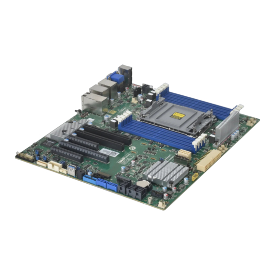
Page 13: Board Image
2.1 Board Image S5642AGM3NRE-2T This picture is representative of the latest board revision available at the time of publishing. The board you receive may not look exactly like the above picture. http://www.tyan.com... -
Page 14: Block Diagram
2.2 Block Diagram S5642 Block Diagram http://www.tyan.com... -
Page 15: Motherboard Mechanical Drawing
2.3 Motherboard Mechanical Drawing http://www.tyan.com... -
Page 16: Board Parts, Jumpers And Connectors
The board you receive may not look exactly like the above diagram. The DIMM slot numbers shown above can be used as a reference when reviewing the DIMM population guidelines shown later in the manual. For the latest board revision, please visit our web site at http://www.tyan.com. http://www.tyan.com... - Page 17 5. RJ45 LAN Port(LAN3) 24. 4-pin FAN Connector (SYS_FAN_6) Dedicated IPMI &USB3.2 Gen1 x2 6. RJ45 LAN Ports (LAN1&LAN2) 25. TYAN Module Header (DBG_HD1) 7. Power Button(Power_BTN1) 26. M.2 Connector (NGFF2) 8. ID LED Button (IDLED_BTN1) 27. 8-Pin Power Connector (PWR2) 9.
- Page 18 CPU ERROR LED(ERR_LED0) xi BMC Heart Beat LED (BMC_LED4) iv CPU ERROR LED(ERR_LED1) xii System Reset LED v NGFF2 LED(D9) (SYS_RST_LED1) xiii BMC DEBUG LED (BMC_LED1) vi NGFF1 LED(LED75) vii Onboard PSMI ALERT LED xiv On board HDD active (PSMI_LED1) LED(HDD_LED1) http://www.tyan.com...
- Page 19 FAN_TACH FAN_PWM Use this header to connect the cooling fan to your motherboard to keep the system stable and reliable. Note: A 4-pin fan is required for fan support 4pin Control DBG_HD1: TYAN Module Header Signal Signal VCC3 FRAME LAD0...
- Page 20 LAN0_LED+ LAN0_LED- RESET_SW# SMBDATA SMBCLK IDLED_SW# INTRUSION# SYS_Air_Inlet LAN1_LED+ NMI_SW# LAN1_LED- PSMI_HD1: PSMI Connector Signal SMB_CLK SMB_DAT PSU_SMBALERT_N V3.3 USB3_FPIO1: Front USB3.2 Gen1 Header Signal Signal P0_RX_N P0_RX_P P0_TX_N P0_TX_P P0_N P0_P OC_N P1_P P1_N P1_TX_P P1_TX_N P1_RX_P P1_RX_N http://www.tyan.com...
- Page 21 SYS FAN PWM4 BMC_PWM7 CPU0 FAN PWM TYPEA_USB1: Vertical (Type_A) USB3.2 Gen1 Connector Signal Signal USB2.0_DATA_N USB2.0_DATA_P USB3.0_RX_N USB3.0_RX_P USB3.0_TX_N USB3.0_TX_P ID LED_BTN1: Rear IDLED Button Signal Signal IDLED_SW# RST_BTN1: Reset Button Signal FP_RST_BTN_N FP_RST_BTN_N PWR_BTN1: POWER Button Signal PWR_BTN1 PWR_BTN1 http://www.tyan.com...
- Page 22 SSATA4_TXP_C Connects to the Serial SSATA4_TXN_C ATA ready drives via the Serial ATA cable. SSATA4_RXN_C SSATA4_RXP_C sSATA5: 7-pin Vertical SATA Connector PIN Define SSATA5_TXP_C Connects to the Serial SSATA5_TXN_C ATA ready drives via the Serial ATA cable. SSATA5_RXN_C SSATA5_RXP_C http://www.tyan.com...
- Page 23 HP0_SCK HP0_SDA CPU01_SMBALERT_N_C HP1_SCK HP1_SDA SlimSAS1: Vertical Slim SAS 8x Connector Signal Name Signal Name CPU1_PE2_ABCD_RX_DN0 CPU1_PE2_ABCD_TX_DP0_C CPU1_PE2_ABCD_RX_DP0 CPU1_PE2_ABCD_TX_DN0_C CPU1_PE2_ABCD_RX_DN1 CPU1_PE2_ABCD_TX_DP1_C CPU1_PE2_ABCD_RX_DP1 CPU1_PE2_ABCD_TX_DN1_C BP_TYPEA PE_HD0_SMB_CLK PE_WAKE_N0 PE_HD0_SMB_DAT SLIMSAS_NVME0_DP PCIE_SLIMSAS_RST_N SLIMSAS_NVME0_DN CPRSNTA- CPU1_PE2_ABCD_RX_DN2 CPU1_PE2_ABCD_TX_DP2_C CPU1_PE2_ABCD_RX_DP2 CPU1_PE2_ABCD_TX_DN2_C CPU1_PE2_ABCD_RX_DN3 CPU1_PE2_ABCD_TX_DP3_C CPU1_PE2_ABCD_RX_DP3 CPU1_PE2_ABCD_TX_DN3_C http://www.tyan.com...
- Page 24 PCH_SSATA_0_3: 36-pin Vertical Mini-SAS HD Connector (SATA 3.0 signals) Signal Signal PCH_SSATA_0-3_A1 SGPIO_SSATA_CLK SGPIO_SSATA_LOAD SSATA1_RXP_C SSATA0_RXP_C SSATA1_RXN_C SSATA0_RXN_C SSATA3_RXP_C SSATA2_RXP_C SSATA3_RXN_C SSATA2_RXN_C SSGPIO_DO_0R SSGPIO_DI_0R SAS1_CTYPE SSATA1_TXP_C SSATA0_TXP_C SSATA1_TXN_C SSATA0_TXN_C SSATA3_TXP_C SSATA2_TXP_C SSATA3_TXN_C SSATA2_TXN_C http://www.tyan.com...
- Page 25 SATA1_RXN_C SATA0_RXN_C SATA3_RXP_C SATA2_RXP_C SATA3_RXN_C SATA2_RXN_C SGPIO_DO_0R SGPIO_DI_0R SAS0_CTYPE SATA1_TXP_C SATA0_TXP_C SATA1_TXN_C SATA0_TXN_C SATA3_TXP_C SATA2_TXP_C SATA3_TXN_C SATA2_TXN_C NC_PCH_SATA_0-7_A10 SGPIO_SATA_CLK SGPIO_SATA_LOAD SATA5_RXP_C SATA4_RXP_C SATA5_RXN_C SATA4_RXN_C SATA7_RXP_C SATA6_RXP_C SATA7_RXN_C SAA6_RXN_C SGPIO_DO_1R SGPIO_DI_1R SAS1_CTYPE SATA5_TXP_C SATA4_TXP_C SATA5_TXN_C SATA4_TXN_C SATA7_TXP_C SATA6_TXP_C SATA7_TXN_C SATA6_TXN_C http://www.tyan.com...
- Page 26 M2_SMB_DAT_R PCH_PE0_M2_0_RX_P PCH_PE0_M2_0_TX_N M2_PERST_N_R PCH_PE0_M2_0_TX_P M2_2_PEWAKE_N CLK_100M_M2_DN CLK_100M_M2_DP PE_M.2_DETECT_N VCC3 VCC3 VCC3 J133: Select PECI to BMC or PCH Jumper Signal Signal 1KK to VCC3_AUX 10K to GND (Default) Pin1-2 closed: PP-PECI to BMC Pin1-2 open: NI-PECI to PCH http://www.tyan.com...
- Page 27 Signal Signal Alert_Buff Alert_Buff_B 1-2: Normal Mode (Default) 2-3: enable PSU Throttling function Mode J120: System Buzzer Jumper Signal Signal VCC5_BZ BUZ_1 BUZ_2 (Default) Pin3-4 closed: Normal Mode Pin2-3 closed: Disable PC Beep Pin1-4 closed: Use the external speaker http://www.tyan.com...
-
Page 28: Led Definitions
2.5 LED Definitions http://www.tyan.com... - Page 29 7.PSMI_LED1 PSMI State Description ALERT LED PSMI alert status is normal PSMI alert status is abnormal Signal VCC3 CAT_LED_C 8.CAT_LED1 CPU CAT ERROR LED State Description CPU status is normal CPU status is abnormal 10. ID_LED1 ID LED Signal http://www.tyan.com...
- Page 30 The LED blinks per half second to indicate Blinking Green that the BMC controller (HW) is working normally Signal VCC3 On board HDD_ACT_LED_N 14.HDD_LED1 HDD active State Description None Blinking Blue On board SATA and NGFF active LED http://www.tyan.com...
-
Page 31: Installing The Processor And Heatsink
2.6 Installing the Processor and Heatsink The types of processors supported by the S5642 are listed in the 1.2 Hardware Specifications section on page 4. Check our website at http://www.tyan.com ® the latest list of validated Intel processors for this specific motherboard. - Page 32 Align the heatsink with the CPU socket by the guide pins and make sure the gold arrow is located in the correct direction. Then place the heatsink onto the top of the CPU socket. http://www.tyan.com...
- Page 33 To secure the heatsink, use a Security T30 Security Torx to tighten the screws in a sequential order (1->2->3->4). When dissembling the heatsink, loosen the screws in reverse order (4->3->2->1). Connect the heatsink power cable to mainboard connector. http://www.tyan.com...
-
Page 34: Thermal Interface Material
CPU lid (applying too much will actually reduce the cooling). NOTE: Always check with the manufacturer of the heat sink & processor to ensure that the thermal interface material is compatible with the processor and meets the manufacturer’s warranty requirements. http://www.tyan.com... -
Page 35: Tips On Installing Motherboard In Chassis
Be especially careful to look for extra stand-offs. If there are any stand-offs present that are not aligned with a mounting hole on the motherboard, it will likely short components on the back of the motherboard when installed. This will cause malfunction and/or damage to your motherboard. http://www.tyan.com... - Page 36 Some chassis include plastic studs instead of metal. Although the plastic studs are usable, MiTAC recommends using metal studs with screws that will fasten the motherboard more securely in place. Below is a chart detailing what the most common motherboard studs look like and how they should be installed. http://www.tyan.com...
-
Page 37: Installing The Memory
2.9 Installing the Memory Before installing memory, ensure that the memory you have is compatible with the motherboard and processor. Check the TYAN Web site at http://www.tyan.com details of the type of memory recommended for your motherboard. (4+4) DDR4 288-pin DIMM slots ... - Page 38 1, 2, 3, 4, 5, 6, 7, or 8 # of DIMMs Populated per channel 1DPC DIMM Type RDIMM (w/ECC), LRDIMM non-3DS RDIMM Raw Cards: A/B (2Rx4), C (1Rx4), DIMM construction (1Rx8), E (2Rx8) non-3DS LRDIMM Raw Cards: D/E (4Rx4) http://www.tyan.com...
- Page 39 DDR4 Memory Configuration http://www.tyan.com...
- Page 40 Memory Installation Procedure Follow these instructions to install memory modules into the S5642. Unlock a DIMM socket by Press the retaining clip outwardly in the following illustration. Align the memory module with the socket,such that the DIMM NOTCH match the KEY SLOT on the socket.
-
Page 41: Attaching Drive Cables
2.10 Attaching Drive Cables Attaching SATA Cables S5642 is equipped with two (2) Serial ATA (SATA) channel. Connections for the drives are very simple. There is no need to set Master/Slave jumpers on SATA drives. If you are in need of SATA/SAS cables or power adapters please contact your place of purchase. -
Page 42: Installing Add-In Cards
Doing so allows air to circulate within the chassis more easily, thus improving cooling for all installed devices. NOTE: You must always unplug the power connector from the motherboard before performing system hardware changes to avoid damaging the board or expansion device. http://www.tyan.com... -
Page 43: Connecting External Devices
Dedicate to IPMI LAN3 VGA Port LAN4 LAN2 ID_Button Audio Jack COM1 Port USB2.0 x 2 USB3.2Gen1 x2 LAN1 S5642AGM3NRE-2T Dedicate to IPMI VGA Port LAN2 LAN1 Audio Jack ID_Button COM1 Port USB2.0 x 2 USB3.2Gen1 x 2 S5642AGMNRE http://www.tyan.com... - Page 44 (Link/Activity) (Speed) No Link Link Solid Green Solid Green 100 Mbps Active Blinking Green Solid Green Link Solid Green Solid Yellow 1000 Mbps Active Blinking Green Solid Yellow Link Solid Yellow Solid Yellow (10Gbps) Active Blinking Yellow Solid Yellow http://www.tyan.com...
-
Page 45: Installing The Power Supply
2.13 Installing the Power Supply There are Three (3) power connectors on your S5642 motherboard. The S5642 supports EPS 12V power supply. PWR1: ATX 24-Pin Power Connector Signal Signal VCC3 VCC3 VCC3 VCC12N VCC5 PSON_N VCC5 ATXPG VCC5SB VCC5 P12VIN... -
Page 46: Chapter 3: Bios Setup
Exit current menu <F1> General help <F2> Previous values <F3> Load the Optimal default configuration values of the menu <F4> Save and exit <K> Scroll help area upwards <M> Scroll help area downwards <PgUp> / <PgDn> Move cursor to next/previous page http://www.tyan.com... - Page 47 BIOS menus are continually changing due to continual BIOS updates over the product lifespan of the motherboard. The BIOS menus provided are current as of the date when this manual was written. Please visit TYAN’s website at http://www.tyan.com for information on BIOS updates available for this specific motherboard.
-
Page 48: Main Menu
Note that the options listed below are for options that can directly be changed within the Main Setup screen. BIOS Information It displays BIOS related information. Product Name It displays Product information. BIOS Version It displays BIOS version information Build Date and Time It displays the time when built Access Level Administrator http://www.tyan.com... - Page 49 Set the Date. Use Tab to switch between Date elements. Default Ranges: Year: 1998-9999 Months: 1-12 Days: dependent on month Range of Years may vary System Time Adjust the system clock. HH (24 hours format): MM (Minutes): SS (Seconds) http://www.tyan.com...
-
Page 50: Advanced Menu
Option ROM Dispatch Policy Option ROM Dispatch Policy S5 RTC Wake Settings S5 RTC Wake Settings Trusted Computing Trusted Computing settings. ACPI Settings System ACPI Parameters AST2500 Super IO Configuration System Super IO Chip Parameters Power Management Power Management http://www.tyan.com... - Page 51 This item support INTEL CPU, sign the CPU will record current CPU. Once BIOS checked different with registered CPU, show WARNING message on POST screen. Memory Registration Sign the Memory will record current Memory. Once BIOS checked different with registered Memory, show WARNING message on POST screen. http://www.tyan.com...
- Page 52 VLAN Configuration (MAC: XXXXXXXXXXXX) VLAN Configuration (MAC: XXXXXXXXXXXX) MAC: XXXXXXXXXXXX --- IPV4 Network Configuration Configure network parameters. (MAC: XXXXXXXXXXXX) MAC: XXXXXXXXXXXX --- IPV6 Network Configuration Configure IPV6 network parameters. (MAC: XXXXXXXXXXXX) Driver Health Provides Health Status for the Drivers/Controllers. http://www.tyan.com...
- Page 53 On Board LAN1 (X550) Onboard Device has: UEFI Legacy [ ] Embedded ROM(s). VIDx8086; DID x1563 @ s0|BxC5|Dx0|Fx0 Disabled / Enabled On Board LAN2 (X550) Onboard Device has: UEFI Legacy [ ] Embedded ROM(s). VIDx8086; DID x1563 @ s0|BxC5|Dx0|Fx1 Disabled / Enabled http://www.tyan.com...
- Page 54 Enable or Disable Option ROM execution for selected Slot. Disabled / Enabled 3.3.2 S5 RTC Wake Settings RTC Wake system from S4/S5 Enable or disable System wake on alarm event. When enabled, system will wake on the hr::min::sec specified. Disabled / Fixed time / Dynamic time http://www.tyan.com...
- Page 55 3.3.3 Trusted Computing Security Device Support Enable or Disable BIOS support for security device. O.S. will not show Security device. O.S. will not show Security Device. TCG EFI protocol and INT1A interface will not be available. Enabled / Disabled http://www.tyan.com...
- Page 56 Enable ACPI Auto Configuration Enables or Disables BIOS ACPI Auto Configuration Disabled / Enabled Enable Hibernation Enables or Disables System ability to Hibernate (OS/S4 Sleep state). This option may not be effective with some operating systems. Disabled / Enabled http://www.tyan.com...
- Page 57 3.3.5 AST2500 Super IO Configuration Serial Port 1 Configuration Set Parameters of Serial Port 1 (COMA) Serial Port 2 Configuration Set Parameters of Serial Port 2 (COMB) http://www.tyan.com...
- Page 58 / IO=3F8h, IRQ=3, 4, 5, 6, 7, 9, 10, 11, 12; / IO=2F8h; IRQ=3, 4, 5, 6, 7, 9, 10, 11, 12; / IO=3E8h, IRQ=3, 4, 5, 6, 7, 9, 10, 11, 12; / IO=2E8h, IRQ=3, 4, 5, 6, 7, 9, 10, 11, 12; http://www.tyan.com...
- Page 59 / IO=3F8h, IRQ=3, 4, 5, 6, 7, 9, 10, 11, 12; / IO=2F8h; IRQ=3, 4, 5, 6, 7, 9, 10, 11, 12; / IO=3E8h, IRQ=3, 4, 5, 6, 7, 9, 10, 11, 12; / IO=2E8h, IRQ=3, 4, 5, 6, 7, 9, 10, 11, 12; http://www.tyan.com...
- Page 60 3.3.6 Power Management Configuration CPU Power and Performance Policy CPU Power and Performance Policy Performance / Balanced Power / Power http://www.tyan.com...
- Page 61 Console Redirection Settings The settings specify how the host computer (which the user is using) will exchange data. Both computers should have the same or compatible settings. NOTE: Console Redirection Settings menu only available when Console Redirection was set to [Enabled]. http://www.tyan.com...
- Page 62 1’s in the data bits is odd. Mark: parity bit is always 1. Space: parity bit is always 0. Mark and Space parity do not allow for error detection. None / Even / Odd / Mark / Space http://www.tyan.com...
- Page 63 With this mode enabled only text will be sent. This is to capture Terminal data. Disabled / Enabled Resolution 100x31 Enable or disable extended terminal resolution. Disabled / Enabled Putty KeyPad Select FunctionKey and KeyPad on Putty. VT100 / LINUX / XTERMR6 / SCO / ESCN / VT400 http://www.tyan.com...
- Page 64 1’s in the data bits is odd. Mark: parity bit is always 1. Space: parity bit is always 0. Mark and Space parity do not allow for error detection. None / Even / Odd / Mark / Space http://www.tyan.com...
- Page 65 With this mode enabled only text will be sent. This is to capture Terminal data. Disabled / Enabled Resolution 100x31 Enable or disable extended terminal resolution. Disabled / Enabled Putty KeyPad Select FunctionKey and KeyPad on Putty. VT100 / LINUX / XTERMR6 / SCO / ESCN / VT400 http://www.tyan.com...
- Page 66 When Bootloader is selected, then Legacy Console Redirection is disabled before booting to legacy OS. When Always Enable is selected, then Legacy Console Redirection is enabled for legacy OS. Default setting for this option is set to Always Enable. Always Enable / BootLoader http://www.tyan.com...
- Page 67 VT-UTF8 / VT100 / VT100+ / ANSI Bits per Second EMS Select serial port transmission speed. The speed must be matched on the other side. Long or noisy lines may require lower speeds. 115200 / 9600 / 19200 / 38400 / 57600 http://www.tyan.com...
- Page 68 ‘start’ signal can be sent to restart the flow. Hardware flow control uses two wires to send start/stop signal. None / Hardware RTS/CTS / Software Xon/Xoff Data Bits EMS / Parity EMS / Stop Bits EMS Read only. http://www.tyan.com...
- Page 69 Enables or Disables 64bit capable Devices to be decoded in Above 4G Address Space(Only if System supports 64 bit PCI Decoding). Enabled / Disabled SR-IOV Support If system has SR-IOV capable PCIe devices, this option Enables or Disables Single root IO virtualization Support. Enabled / Disabled http://www.tyan.com...
- Page 70 Displays and provides option to change the Common RefCode Settings. Memory Configuration Displays and provides option to change the Memory Settings. IIO Configuration Displays and provides option to change the IIO Settings. Advanced Power Management Configuration Displays and provides option to change the Power Management Settings. http://www.tyan.com...
- Page 71 Note: A change to this option requires the system to be powered off and then back on before the setting takes effect. Disabled / Enabled Enable SMX Enables Safer Mode Extensions. Disabled / Enabled http://www.tyan.com...
- Page 72 Selects the allocation size used to assign mmioh resources. Total mmioh space can be up to 32xgranularity. Per stack mmioh resource assignments are multiples of the granularity where 1 unit per stack is the default allocation. 1G / 4G / 16G / 64G / 256G / 1024G http://www.tyan.com...
- Page 73 UMA-Based Clustering UMA Based Clustering options include Disable (ALL2ALL), Hemisphere (2 cluster, not supported on ICX).These option are only valid when SNC is disabled. If SNC is enabled, UMA-Based Clustering is automatically disabled by BIOS. Disable (All2All) / Hemisphere (2-clusters) http://www.tyan.com...
- Page 74 Enable – Portions of memory reference code will be skipped when possible to increase boot speed on warm boots. Disable – Disables this feature. Auto– sets it to the MRC default setting; current default is Disable. Disabled / Enabled http://www.tyan.com...
- Page 75 Enable – Enables the legacy rank margin tool to run after DDR4 memory training. Disable– Disables this feature. Current default is Enable. Should be disabled in production releases. Disabled / Enabled Memory RAS Configuration Displays and provides option to change the Memory RAS Settings http://www.tyan.com...
- Page 76 Enable Mirror on entire memory for TAD0. Enabled / Disabled UEFI ARM Mirror Imitate behavior of UEFI based Address Range Mirror with Setup option Enabled / Disabled Correctable Error Threshold Correctable Error Threshold (0x01 – 0x7fff) used for sparing, tagging, and leaky bucket. 7FFF http://www.tyan.com...
- Page 77 Selects the number of hours (1-24) required to complete full scrub. A value of zero means auto! 3.3.9.4 IIO Configuration Socket0 Configuration Press <Enter> to bring up the Socket0 Configuration Intel® VT for Directed I/O (VT-d) Press <Enter> to bring up the Intel® VT for Directed I/O (VT-d) Configuration menu. http://www.tyan.com...
- Page 78 Enable/Disable PCIe Hot Plug globally. no / yes PCIe ACPI Hot Plug Enable/Disable PCIe ACPI Hot Plug globally, or allow per-port control. When Disabled, MSI is generated on HP event. When enabled, _HPGPE message is generated. no / yes / Per individual port http://www.tyan.com...
- Page 79 Selects PCIe port Bifurcation for selected slot(s). Auto / x4x4x4x4 / x4x4x8 / x8x4x4 / x8x8 / x16 IOU4 (IIO PCIe Port 5) Selects PCIe port Bifurcation for selected slot(s). Auto / x4x4x4x4 / x4x4x8 / x8x4x4 / x8x8 / x16 http://www.tyan.com...
- Page 80 Auto / Disabled / Enabled Hot Plug Capable This option specifies if the link is considered Hot Plug capable. Auto / Disabled / Enabled Surprise Hot Plug Capable This option specifies if the link is considered Hot Plug capable. Disabled / Enabled http://www.tyan.com...
- Page 81 This option enables/disables the ASPM (L1) support for the downstream devices. Auto / L1 Only / L0s only / Disabled Hide Port? User can force to hide this root port from OS. no / yes MCTP Enable/Disable MCTP no / yes http://www.tyan.com...
- Page 82 Auto / Enabled / Disabled X2APIC Opt Out Enable/Disable X2APIC_OPT_OUT bit Enabled / Disabled Pre-boot DMA Protection Enable DMA Protection in Pre-boot environment (If DMAR table is installed in DXE and If VTD_INFO_PPI is installed in PEI.) Enabled / Disabled http://www.tyan.com...
- Page 83 3.3.9.4.3 Intel® VMD Technology http://www.tyan.com...
- Page 84 Disabled / Enabled VMD Config for IOU2 Enable/Disable VMD in this Stack. Disabled / Enabled VMD Config for IOU3 Enable/Disable VMD in this Stack. Disabled / Enabled VMD Config for IOU4 Enable/Disable VMD in this Stack. Disabled / Enabled http://www.tyan.com...
- Page 85 Disabled / Enabled Intel AIC Retimer/AIC SSD HW at Stack4 Announce Intel AIC Retimer/AIC SSD HW at stack4(Port4A-4D). Override IOUx bifurcation if required Disabled / Enabled Intel AIC Retimer/AIC SSD HW at Stack5 Announce Intel AIC Retimer/AIC SSD HW at stack5(Port5A-5D). http://www.tyan.com...
- Page 86 P State Control Configuration Sub Menu, include Turbo, XE and etc. Hardware PM State Control Hardware P-State setting CPU C State Control CPU C State setting. SOCKET RAPL Config SOCKET RAPL Configuration Sub Menu – TURBO_POWER_LIMIT CSR & MSR http://www.tyan.com...
- Page 87 Intel SST-PP Select allows user to choose from up to two additional base frequency conditions. Base / Config 3 / Config 4 Energy Efficient Turbo Energy Efficient Turbo Disable, MSR 0x1FC [19]. Enabled / Disabled Turbo Mode Enable/Disable processor Turbo Mode (requires EMTTM enabled too). Disabled / Enabled http://www.tyan.com...
- Page 88 Disable: Hardware choose a P-state based on OS Request (Legacy P-States) Native Mode: Hardware choose a P-state based on OS guidance Out of Band Mode: Hardware autonomously choose a P-state (no OS guidance) Disabled / Native Mode / Out of Band Mode / Native Mode with No Legacy Support http://www.tyan.com...
- Page 89 C0/C1 state / C2 state / C6 (non Retention) state / Auto CPU C6 report Enable/Disable CPU C6 (ACPI C3) report to OS. Disabled / Enabled / Auto Enhanced Halt State (C1E) Core C1E auto promotion Control. Take effect after reboot. Disabled / Enabled http://www.tyan.com...
- Page 90 TDP value should be maintained. If the value is 0, the fused value will be programmed. PL2 Limit Enable/Disable PL2. If this option is disabled, BIOS will program the default values for PL2 Power Limit and PL2 Time Window. Disabled / Enable http://www.tyan.com...
- Page 91 PL2 value in seconds. The value may vary from 0 to 448. Indicates the time window over which TDP value should be maintained. If the value is 0, the fused value will be programmed. 3.3.10 Memory Topology Read only. http://www.tyan.com...
- Page 92 3.3.11 Server ME Configuration Altitude The altitude of the platform location above the sea level, expressed in meters. The hex number is decoded as 2’s complement signed integer. Provide the 8000h value if the altitude is unknown. 8000 http://www.tyan.com...
- Page 93 3.3.12 SATA Configuration SATA Configuration SATA devices and settings. SSATA Configuration sSATA devices and settings. http://www.tyan.com...
- Page 94 Identify the SATA port is connected to Solid State Drive or Hard Disk Drive. AHCI / RAID Support Aggressive Link Power Management Enables/Disables SALP. Disabled / Enabled Port 0/1/2/3/4/5/6/7 Enable or Disable SATA Port. Disabled / Enabled Hot Plug Designates this port as Hot Pluggable. Disabled / Enabled http://www.tyan.com...
- Page 95 Disabled / Enabled SATA Device Type Identify the SATA port is connected to Solid State Drive or Hard disk Drive. Hard Disk Drive / Solid State Drive 3.3.12.2 sSATA Configuration sSATA Controller Enable or Disable sSATA Controller. Disabled / Enabled http://www.tyan.com...
- Page 96 Identify the SATA port is connected to Solid State Drive or Hard disk Drive. Hard Disk Drive / Solid State Drive sSATA Topology Identify the Secondary SATA Topology if it is Default or ISATA or Flex or DirectConnect or M2. Unknown / ISATA / Direct Connect / Flex / M2 http://www.tyan.com...
- Page 97 3.3.13 PCH Configuration PCH Devices ® Enable/Disable Intel IO Controller Hub devices. PCI Express Configuration PCI Express Configuration settings. USB Configuration USB Configuration Settings. ADR Configuration Automatic DIMM Refresh (ADR) Configuration. http://www.tyan.com...
- Page 98 3.3.13.1 PCH Devices PCH state after G3 Select S0/S5 for ACPI state after a G3. S0 / S5 / Leave power state unchanged http://www.tyan.com...
- Page 99 3.3.13.2 PCI Express Configuration PCI Express Root Port 1~20 PCI Express Root Port 1~20 Settings. http://www.tyan.com...
- Page 100 L1 Substates PCI Express L1 Substates settings. Disabled / L1.1 / L1.2 / L1.1 & L1.2 PCIe Speed Configure PCIe Speed. Auto / Gen1 / Gen2 / Gen3 Max Payload Size PCIE Max Payload Size Selection. MPL128B / MPL256B http://www.tyan.com...
- Page 101 3.3.13.3 USB Configuration XHCI Idle L1 Enabled XHCI Idle L1. Disabled to workaround USB3 hot plug will fail after 1 hot plug removal. Please put the system to G3 for the new settings to take effect. Disabled / Enabled http://www.tyan.com...
- Page 102 Enable/Disable ADR Timer Held-off for DEBUG PURPOSES ONLY!. Platform-POR / Enabled / Held-off ADR timer expire time Select proper ADR timer value: 25uS, 50uS, 100uS or 0. Platform-POR / 25 uS / 50 uS / 100 uS / 0 us http://www.tyan.com...
- Page 103 USB Mass Storage Driver Support Enable/Disable USB Mass Storage Driver Support. Disabled / Enabled Port 60/64 Emulation Enables I/O Port 60h/64h emulation support. This should be enabled for the complete USB keyboard legacy support for non-USB aware OSes. Disabled / Enabled http://www.tyan.com...
- Page 104 Mass storage device emulation type. ‘Auto’ enumerates devices according to their media format. Optical drives are emulated as ‘CDROM’, drives with no media will be emulated according to a drive type. Auto / Floppy / Forced FDD / Hard Disk / CD-ROM http://www.tyan.com...
- Page 105 3.3.15 NVMe Configuration This page shows the Device Name you installed. Press Enter to read the device information. If no NVME device is installed, it shows no NVME device is found. Read only. http://www.tyan.com...
- Page 106 Turn on/off Spread Spectrum Setting for IsCLK. Enabled / Disabled Chassis Intrusion Detection Enabled: When a chassis open event is detected, the BIOS will display the event. Enabled / Disabled NMI Button Enable or Disable NMI button. Enabled Disabled http://www.tyan.com...
- Page 107 3.3.17 Redfish Host Interface Configuration Redfish Enable/Disable AMI Redfish. Enabled Disabled Authentication mode Select authentication mode Basic Authentication / Session Authentication IP address Enter IP address IP Mask address Enter IP Mask address IP Port Enter IP Port http://www.tyan.com...
- Page 108 Enable Ipv4 HTTP Boot Support. If disabled IPV4 HTTP boot option will not be created. Disabled / Enabled Ipv6 PXE Support Enable Ipv6 PXE Boot Support. If disabled IPV6 PXE boot option will not be created. Disabled / Enabled http://www.tyan.com...
- Page 109 Enable Ipv6 HTTP Boot Support. If disabled IPV6 HTTP boot option will not be created. Disabled / Enabled PXE boot wait time Wait time to press ESC key to abort the PXE boot. Media detect count Number of times presence of media will be checked. http://www.tyan.com...
- Page 110 Nvidia GeForce / Quardro GPU and any VGA card. PWM Minimal Duty Cycle PWM Minimal Duty Cycle (%). NOTE: This item is available when Fan Speed Control is set to [Manual]. BMC Alert Beep Enable/Disable BMC Alert Beep. On / Off http://www.tyan.com...
- Page 111 3.3.19.1 Sensor Data Register Monitoring When you enter the Sensor Data Register Monitoring submenu, you will see the following dialog window pop out. Please wait 8~10 seconds. NOTE 1: SDR can not be modified. Read only. http://www.tyan.com...
- Page 112 http://www.tyan.com...
- Page 113 http://www.tyan.com...
- Page 114 Enables the detecting and enabling of ADR. This is not available if eADR is enabled since eADR requires ADR to be enabled. Enabled / Disabled Assert ADR on Reset Assert ADR on Reset. Enabled / Disabled Assert ADR on Shutdown Assert ADR on Shutdown. Enabled / Disabled http://www.tyan.com...
- Page 115 3.3.21 CPU Registration Sign-up the current CPU This item support INTEL CPU, sign the CPU will record current CPU. Once BIOS checked different with registered CPU, show WARNING message on POST screen. Deregistration / Sign-up / Keep Current Status http://www.tyan.com...
- Page 116 3.3.22 Memory Registration Sign-up the current Memory Sign the Memory will record current Memory. Once BIOS checked different with registered Memory, show WARNING message on POST screen. Deregistration / Sign-up / Keep Current Status http://www.tyan.com...
- Page 117 3.3.23 Tls Auth Configuration Server CA Configuration Press <Enter> to configure Server CA. Client Cert Configuration Press <Enter> to configure Client Cert. http://www.tyan.com...
- Page 118 3.3.23.1 Server CA Configuration Enroll Cert Press <Enter> to enroll cert. Delete Cert Press <Enter> to delete cert. http://www.tyan.com...
- Page 119 3.3.23.1.1 Enroll Cert Enroll Cert Using File Enroll Cert Using File. Cert GUID Input digit character in 11111111-2222-3333-4444-1234567890ab format. Commit Changes and Exit Commit Changes and Exit. Discard Changes and Exit Discard Changes and Exit. http://www.tyan.com...
- Page 120 3.3.23.1.2 Delete Cert FE9C6606-8B49-44A3-8B6B-DEA3A0E032 GUID for CERT. Disabled / Enabled http://www.tyan.com...
- Page 121 3.3.24 iSCSI Configuration Host iSCSI Configuration Host iSCSI Configuration http://www.tyan.com...
- Page 122 Add an Attempt. Delete Attempts Delete one or more attempts. Change Attempt Order Change the order of Attempts using +/- keys. Use arrow keys to select the attempt then press +/- to move the attempt up/down in the attempt order list. http://www.tyan.com...
- Page 123 3.3.24.1.1 Add an Attempt NOTE: Only LAN1 supports iSCSI function. MAC xx:xx:xx:xx:xx:xx (Intel® I210 Gigabit Network Connection) PFA: Bus 2 / Dev 0 / Func 0. http://www.tyan.com...
- Page 124 IPv4 / IPv6 / Autoconfigure Connection Retry Count The minimum value is 0 and the maximum is 16. 0 means no retry. Connection Establishing Timeout The timeout value in milliseconds. The minimum value is 100 milliseconds and the maximum is 20 seconds. http://www.tyan.com...
- Page 125 Hexadecimal representation of the LU number. Examples are: 4752-3A4F-6b7e- 3F99, 6734-9-156f-127, 4186-9. Authentication Type Authentication method: CHAP, Kerberos, or None. CHAP / None Save Changes Must reboot system manually for changes to take place. Back to Previous Page Back to Previous Page. http://www.tyan.com...
- Page 126 Disabled / Enabled Attempt 2 MAC xx:xx:xx:xx:xx:xx, PFA: Bus 2 / Dev 0 / Func 0, iSCSI mode: Disabled, IP version: IPv4. Disabled / Enabled Commit Changes and Exit Commit Changes and Exit. Discard Changes and Exit Discard Changes and Exit. http://www.tyan.com...
- Page 127 Change the order of Attempts using +/- keys. Use arrow keys to select the attempt then press +/- to move the attempt up/down in the attempt order list. Attempt 1 / Attempt 2 Commit Changes and Exit Commit Changes and Exit. Discard Changes and Exit Discard Changes and Exit. http://www.tyan.com...
- Page 128 3.3.24 VLAN Configuration (MAC:xxxxxxxxxxxx) Enter Configuration Menu Press ENTER to enter configuration menu for VLAN configuration. http://www.tyan.com...
- Page 129 3.3.24.1 Enter Configuration Menu VLAN ID VLAN ID of new VLAN or existing VLAN, valid value is 0~4094. Priority 802.1Q Priority, valid value is 0~7. Add VLAN Create a new VLAN or update existing VLAN. Remove VLAN Remove selected VLANs. http://www.tyan.com...
- Page 130 3.3.24 MAC:xxxxxxxxxxxx - IPv4 Network Configuration Configured Indicate whether network address configured successfully or not. Disabled / Enabled Save Changes and Exit Save Changes and Exit. http://www.tyan.com...
- Page 131 3.3.25 MAC:xxxxxxxxxxxx - IPv6 Network Configuration Enter Configuration Menu Press ENTER to enter configuration menu for IPv6 configuration. http://www.tyan.com...
- Page 132 Duplicate Address Detection is not performed. Policy Automatic or manual. Automatic / Manual NOTE: The Advanced Configuration submenu is available when Policy is set to [Manual]. Advanced Configuration Configure the interface manually. IP address, gateway address, and DNS server address can be configured. http://www.tyan.com...
- Page 133 Save Changes and Exit. 3.3.26 Intel® I210 Gigabit Network Connection Configuration Firmware Image Properties View device firmware version information. NIC Configuration Click to configure the network device port. Blink LEDs Blink LEDs for a duration up to 15 seconds. http://www.tyan.com...
- Page 134 3.3.26.1 Firmware Image Properties Configuration http://www.tyan.com...
- Page 135 Enables power on of the system via LAN. Note that configuring Wake on LAN in the operating system does not change the value of this setting, but does override the behavior of Wake on LAN in OS controlled power states. Disabled / Enabled http://www.tyan.com...
- Page 136 Intel® PRO/1000 9.4.06 PCI-E Provides Health Status for the Drivers/Controllers. Healthy Intel® 10GbE Driver 7.8.13x64 Provides Health Status for the Drivers/Controllers. Healthy Intel® 10GbE Driver 7.8.13x64 Provides Health Status for the Drivers/Controllers. Healthy http://www.tyan.com...
- Page 137 This is a sample screenshot of the Driver Health. The information displayed here may vary in accordance with the card you installed. Controller 6161BB18 Child 0 Provides Health Status for the Drivers/Controllers. Healthy Intel® I210 Gigabit Network Connection Provides Health Status for the Drivers/Controllers. Healthy http://www.tyan.com...
- Page 138 This is a sample screenshot of the Driver Health. The information displayed here may vary in accordance with the card you installed. Controller 6125FD98 Child 0 Provides Health Status for the Drivers/Controllers. Healthy Intel® Ethernet Converged Network Adapter X550-T2 Provides Health Status for the Drivers/Controllers. Healthy http://www.tyan.com...
- Page 139 3.3.27.3 Intel® 10GbE Driver Controller 6125E898 Child 0 Provides Health Status for the Drivers/Controllers Healthy Intel® Ethernet Converged Network Adapter X550-T2 Provides Health Status for the Drivers/Controllers Healthy http://www.tyan.com...
-
Page 140: Server Management
Enter value Between 3 to 6 min for FRB-2 Timer Expiration value. FRB-2 Timer Policy Configure how the system should respond if the FRB-2 Timer expires. Not available if FRB-2 Timer is disabled. Do Nothing / Reset / Power Down / Power Cycle http://www.tyan.com... - Page 141 Configure how the system should respond if the OS Boot Watchdog Timer expires. Not available if OS Boot Watchdog timer is disabled. Do Nothing / Reset / Power Down / Power Cycle BMC network configuration Configure BMC network parameters. http://www.tyan.com...
- Page 142 Enable/Disable BMC Share Nic. Enabled / Disabled Configuration Address Source Select the configure LAN channel parameters statically or dynamically (by BIOS or BMC). Unspecified option will not modify any BMC network parameters during BIOS phase. Unspecified / Static / DynamicBmcDhcp / DynamicBmcNonDhcp http://www.tyan.com...
- Page 143 Configure IPV6 Support Server Management Port 1 IPV6 Support Enable or Disable LAN1 IPV6 Support. Enabled / Disabled Server Management Port 2 IPV6 Support Enable or Disable LAN1 IPV6 Support. Enabled / Disabled http://www.tyan.com...
-
Page 144: Security
Set user password in the Create New Password window. After you key in the password, the Confirm New Password window will pop out to ask for confirmation. Security Frozen Mode Enable or disable HDD security freeze lock. Disable to support secure erase function. For AHCI SATA ports only. Enabled / Disabled http://www.tyan.com... - Page 145 Restore Factory Keys Force System to User Mode. Install factory default Secure Boot Key databases Reset To Setup Mode Delete all Secure Boot Key databases from NVRAM Key Management Enables expert users to modify Secure Boot Policy variables without full authentication. http://www.tyan.com...
- Page 146 Copy NVRAM content of Secure Boot variables to files in a root folder on a file system device Enroll Efi Image Allow the image to run in Secure Boot mode. Enroll SHA256 has of the binary into Authorized signature Database (db). http://www.tyan.com...
- Page 147 1. Public Key Certificate in: a) EFI_SIGNATURE_LIST b) EFI_CERT_X509 (DER encoded) c) EFI_CERT_RSA2048 (bin) d) EFI_CERT_SHA256, 384, 512 (bin) 2. Authenticated UEFI Variable 3. EFI PE/C0FF Image (SHA256) Key source: Default, External, Mixed, Test Details / Export / Update / Append / Delete http://www.tyan.com...
- Page 148 Enroll Factory Defaults or load certificates from a file: 1. Public Key Certificate in: a) EFI_SIGNATURE_LIST b) EFI_CERT_X509 (DER encoded) c) EFI_CERT_RSA2048 (bin) d) EFI_CERT_SHA256, 384, 512 (bin) 2. Authenticated UEFI Variable 3. EFI PE/C0FF Image (SHA256) Key source: Default, External, Mixed, Test Update / Append http://www.tyan.com...
-
Page 149: Boot
Enable or disable Quiet Boot option. Disabled / Enabled Endless Boot Support Enables or disables Endless Boot Support option. Disabled / Enabled Wait for ‘ESC’ If Error Wait for ‘ESC’ key to be pressed if error occurs. Disabled / Enabled http://www.tyan.com... - Page 150 Boot Option Priorities Boot Option #1~#2 Select the first/second boot device. Device Name / Disabled Add New Boot Option Add a new EFI boot option to the boot order Delete Boot Option Remove an EFI boot option from the boot order http://www.tyan.com...
-
Page 151: Save & Exit
Reset system setup without saving any changes. Save Changes Save changes done so far to any of the setup options. Discard Changes Discard changes done so far to any of the setup options. Restore Defaults Restore/Load Default values for all the setup options. http://www.tyan.com... - Page 152 Save as User Defaults Save the changes done so far as User Defaults. Restore User Defaults Restore the User Defaults to all the setup options. Boot Override Read only. http://www.tyan.com...
-
Page 153: Chapter 4: Diagnostics
BIOS flash failure, you must contact your dealer for a replacement BIOS. There are no exceptions. TYAN does not have a policy for replacing BIOS chips directly with end users. In no event will TYAN be held responsible for damages done by the end user. -
Page 154: Amibios Post Code (Aptio)
South Bridge initialization before microcode loading 0x05 OEM initialization before microcode loading 0x06 Microcode loading 0x07 AP initialization after microcode loading 0x08 North Bridge initialization after microcode loading 0x09 South Bridge initialization after microcode loading 0x0A OEM initialization after microcode loading 0x0B Cache initialization http://www.tyan.com... - Page 155 CPU post-memory initialization is started 0x33 CPU post-memory initialization. Cache initialization 0x34 CPU post-memory initialization. Application Processor(s) (AP) initialization 0x35 CPU post-memory initialization. Boot Strap Processor (BSP) selection 0x36 CPU post-memory initialization. System Management Mode(SMM) initialization 0x37 Post-Memory North Bridge initialization is started http://www.tyan.com...
- Page 156 Reserved for future AMI progress codes S3 Resume Error Codes 0xE8 S3 Resume Failed 0xE9 S3 Resume PPI not Found 0xEA S3 Resume Boot Script Error 0xEB S3 OS Wake Error 0xEC – 0xEF Reserved for future AMI error codes http://www.tyan.com...
- Page 157 South Bridge DXE SMM initialization is started 0x72 South Bridge devices initialization 0x73 South Bridge DXE initialization (South Bridge module specific) 0x74 South Bridge DXE initialization (South Bridge module specific) 0x75 South Bridge DXE initialization (South Bridge module specific) http://www.tyan.com...
- Page 158 Setup Verifying Password 0xA9 Start of Setup 0xAA Reserved for ASL (see ASL Status Codes section below) 0xAB Setup Input Wait 0xAC Reserved for ASL (see ASL Status Codes section below) 0xAD Ready To Boot event 0xAE Legacy Boot event http://www.tyan.com...
- Page 159 System is entering S4 sleep state 0x05 System is entering S5 sleep state 0x10 System is waking up from the S1 sleep state 0x20 System is waking up from the S2 sleep state 0x30 System is waking up from the S3 sleep state http://www.tyan.com...
- Page 160 Status Code Description 0x40 System is waking up from the S4 sleep state 0xAC System has transitioned into ACPI mode. Interrupt controller is in PIC mode. 0xAA System has transitioned into ACPI mode. Interrupt controller is in APIC mode. http://www.tyan.com...
-
Page 161: Appendix I: How To Recover Uefi Bios
UEFI recovery bootloader that would prevent the recovery process itself from working. In no event shall Tyan be liable for direct, indirect, incidental, special or consequential damages arising from the BIOS update or recovery. - Page 162 “Flash update completed. Press any key to reset the system” displayed on screen. 8.Remove the USB disk and reboot. If your system does not have video output or the POST code halts at “FF” on the right-lower portion of the screen, please contact Tyan representatives for RMA service. http://www.tyan.com...
-
Page 163: Appendix Ii: M.2 Latch Installation
This section provides a step-by-step demonstration on how to install a M.2 latch. 1. Take out the M.2 latch packs from the Accessory Box. There are 2 M.2 Latches in the pack. 2. Insert the M.2 latch into the hole and then turn 90 degrees to the left as shown below. http://www.tyan.com... - Page 164 NOTE: The arrow sign on the blue knob is now turned left. 3. Push the blue knob slightly to the left as the arrow shows to lock the M.2 card in place. http://www.tyan.com...
- Page 165 4. The installation of the M.2 latch is now complete. http://www.tyan.com...
- Page 166 (rpm) Temp Sensor: SYS_Air_Outlet(RT3) MB_Air_Inlet(RT2) SYS_FAN1~6/CPU_FAN etc. They detect the system temperature around. NOTE: The system temperature is measured in a scale defined by Intel, not in Fahrenheit or Celsius. http://www.tyan.com...
- Page 167 BIOS Temp Sensor Name Explanation: http://www.tyan.com...
- Page 168 Fan speed of SYS_FAN_5 SYS_FAN_6 Fan speed of SYS_FAN_6 SYS_FAN_7 Fan speed of SYS_FAN_7 SYS_FAN_8 Fan speed of SYS_FAN_8 SYS_FAN_9 Fan speed of SYS_FAN_9 SYS_FAN_10 Fan speed of SYS_FAN_10 SYS_FAN_11 Fan speed of SYS_FAN_11 SYS_FAN_12 Fan speed of SYS_FAN_12 http://www.tyan.com...
- Page 169 NOTE http://www.tyan.com...
-
Page 170: Glossary
(reading to or writing from a disk drive a single time is much faster than doing so repeatedly) there is the possibility of losing your data should the system crash. Information in a buffer is temporarily stored, not permanently saved. http://www.tyan.com... - Page 171 (like soundcards or keyboards) to access the main memory without involving the CPU. This frees up CPU resources for other tasks. As with IRQs, it is vital that you do not double up devices on a single line. Plug-n-Play devices will take care of this for you. http://www.tyan.com...
- Page 172 ROM chip which can, unlike normal ROM, be updated. This allows you to keep ’s ® up with changes in the BIOS programs without having to buy a new chip. TYAN BIOS updates can be found at http://www.tyan.com ESCD (Extended System Configuration Data): a format for storing information about Plug-n-Play devices in the system BIOS.
- Page 173 PXE (Preboot Execution Environment): one of four components that together make up the Wired for Management 2.0 baseline specification. PXE was designed to define a standard set of preboot protocol services within a client with the goal of allowing networked-based booting to boot using industry standard protocols. http://www.tyan.com...
- Page 174 NVIDIA s (graphics communications processing units) and NVIDIA MCPs (media and processors). application Depending on the , NVIDIA SLI can deliver as much as two times the performance of a single GPU configuration. http://www.tyan.com...
- Page 175 CPUs without damaging the sensitive CPU pins. The CPU is lightly placed in an open ZIF socket, and a lever is pulled down. This shifts the processor over and down, guiding it into the board and locking it into place. http://www.tyan.com...
-
Page 176: Technical Support
"TYAN's tech support is some of the most impressive we've seen, with great response time and exceptional organization in general" - Anandtech.com Help Resources: 1. See the beep codes section of this manual. - Page 177 (RMA) number. The RMA number Should be prominently displayed on the outside of the shipping carton and the package should be mailed prepaid. ® TYAN will pay to have the board shipped back to you. Notice for the USA Compliance Information Statement (Declaration of...
Need help?
Do you have a question about the S5642 and is the answer not in the manual?
Questions and answers