Table of Contents
Advertisement
Quick Links
Copyright
Copyright © 2013 MiTAC International Corporation. All rights reserved. No part of
this manual may be reproduced or translated without prior written consent from
MiTAC International Corporation.
Trademark
All registered and unregistered trademarks and company names contained in this
manual are property of their respective owners including, but not limited to the
following.
®
TYAN
is a trademark of MiTAC International Corporation.
®
Intel
is a trademark of Intel
AMI, AMI BIOS are trademarks of AMI Technologies.
®
Microsoft
, Windows
®
Winbond
is a trademark of Winbond Electronics Corporation.
Notice
Information contained in this document is furnished by MiTAC International
Corporation and has been reviewed for accuracy and reliability prior to printing.
MiTAC assumes no liability whatsoever, and disclaims any express or implied
warranty, relating to sale and/or use of TYAN
warranties relating to fitness for a particular purpose or merchantability. MiTAC
retains the right to make changes to product descriptions and/or specifications at
any time, without notice. In no event will MiTAC be held liable for any direct or
indirect, incidental or consequential damage, loss of use, loss of data or other
malady resulting from errors or inaccuracies of information contained in this
document.
S5533
Version 1.0
®
Corporation.
®
are trademarks of Microsoft Corporation.
http://www.tyan.com
®
products including liability or
1
Advertisement
Table of Contents

Related Manuals for TYAN S5533


Summary of Contents for TYAN S5533
- Page 1 Corporation and has been reviewed for accuracy and reliability prior to printing. MiTAC assumes no liability whatsoever, and disclaims any express or implied ® warranty, relating to sale and/or use of TYAN products including liability or warranties relating to fitness for a particular purpose or merchantability. MiTAC retains the right to make changes to product descriptions and/or specifications at any time, without notice.
-
Page 2: About This Guide
Appendix I: Fan and Temp Sensors This section aims to help readers identify the locations of some specific Fan and Temp Sensors on the motherboard. A table of BIOS Temp sensor name explanation is also included for readers’ reference. http://www.tyan.com... -
Page 3: Table Of Contents
3.8 Save & Exit ..................77 Chapter 4: Diagnostics ................79 4.1 Flash Utility ..................79 4.2 AMIBIOS Post Code (Aptio) ............80 Appendix I: Fan and Temp Sensors ............87 Glossary ..................... 89 Technical Support ..................95 http://www.tyan.com... -
Page 4: Before You Begin
Check the box contents! The retail motherboard package should contain the following: 1 x S5533 Motherboard 6 x SATA Single Cable 1 x IO shield 1 x S5533 Quick Installation Guide ® 1 x TYAN Driver CD IMPORTANT NOTE: Sales samples may not come with any of the accessories listed above. -
Page 5: Chapter 1: Instruction
S5533 is capable of offering scalable 32 and 64-bit computing, high- bandwidth memory design, and lightning-fast PCI-E bus implementation. The S5533 not only empowers you in today’s demanding IT environment but also offers a smooth path for future application upgradeability. All of these rich feature sets provide the S5533 with the power and flexibility to meet demanding requirements for today’s IT environments. - Page 6 Non-operating Temp. - 40° C ~ 70° C (-40° F ~ 158° F) Environment In/Non-operating 90%, non-condensing at 35° C Humidity RoHS RoHS 6/6 Compliant Yes Motherboard (1) S5533 Motherboard Manual (1) Quick Installation Guide Package Installation CD (1) TYAN installation CD Contains I/O Shield...
-
Page 7: Software Specifications
1.3 Software Specifications For the latest OS (operation system) support and IPMI Configuration Guide, please visit our Web site for information. http://www.tyan.com... - Page 8 NOTE http://www.tyan.com...
-
Page 9: Chapter 2: Board Installation
Caution! To avoid damaging the motherboard and associated components, do not use torque force greater than 7kgf/cm (6.09 lb/in) on each mounting screw for motherboard installation. Do not apply power to the board if it has been damaged. http://www.tyan.com... -
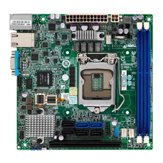
Page 10: Board Image
2.1 Board Image S5533 This picture is representative of the latest board revision available at the time of publishing. The board you receive may not look exactly like the above picture. http://www.tyan.com... -
Page 11: Block Diagram
2.2 Block Diagram S5533 Block Diagram http://www.tyan.com... -
Page 12: Mainboard Mechanical Drawing
2.3 Mainboard Mechanical Drawing http://www.tyan.com... -
Page 13: Board Parts, Jumpers And Connectors
The board you receive may not look exactly like the above diagram. The DIMM slot numbers shown above can be used as a reference when reviewing the DIMM population guidelines shown later in the manual. For the latest board revision, please visit our web site at http://www.tyan.com. http://www.tyan.com... -
Page 14: Jumper Legend
Jumpers Slots BIOS Recovery Mode Jumper (J52) DDR Memory Slot (DIMM_A0) Clear CMOS Jumper (J42) DDR Memory Slot (DIMM_B0) PCIE Gen3 x16 Slot Jumper Legend OPEN - Jumper OFF Without jumper cover CLOSED - Jumper ON With jumper cover http://www.tyan.com... - Page 15 http://www.tyan.com...
- Page 16 J54: SYS_FAN_2 J55: CPU_FAN J77: COM Port Header Signal Signal NONE J82: Fault LED Header Signal power system_fault J50: ME Header Signal Recovery J43: USB Front Panel Header (blue) Signal Signal power power USB_DN USB_DN USB_DP USB_DP GUIDE pin http://www.tyan.com...
- Page 17 http://www.tyan.com...
- Page 18 J83: SGPIO Header for BB HD Board Signal Signal SATA_LOAD SATA_CLOCK SATA_DATAOUT0 SATA_DATAOUT1 J81: Chassis Intrusion Header Signal INTRUDER# Open Open: Use this header to trigger the system chassis intrusion alarm. Short: Use this header to disable the system chassis Short (Default) intrusion alarm. http://www.tyan.com...
- Page 19 http://www.tyan.com...
- Page 20 3. Move the jumper cap to close Pin_2 and Pin_3 for several seconds to Clear CMOS. 4. Put jumper cap back to Pin_1 and Pin_2 (Default setting). Clear CMOS 5. Reconnect power connectors to the motherboard and power on system. http://www.tyan.com...
-
Page 21: Installing The Processor And Heatsink
2.5 Installing the Processor and Heatsink The types of processors supported by the S5533 are listed in the section 1.2 http://www.tyan.com Hardware Specification on page 5. Check our website at ® the latest list of validated Intel processors for this specific motherboard. - Page 22 Remove the CPU protection cap. Install the processor and make sure the gold arrow is located in the right direction. Close the CPU socket cover. Close the socket lever. http://www.tyan.com...
- Page 23 Intel . Please refer to the Intel website: http://www.intel.com ® The following diagram illustrates how to install the heatsink on the Intel H3 Socket: Apply the thermal grease. Install the CPU heatsink. http://www.tyan.com...
- Page 24 Secure the heatsink screws. Connect the heatsink fan cable. http://www.tyan.com...
-
Page 25: Thermal Interface Material
CPU lid (applying too much will actually reduce the cooling). NOTE: Always check with the manufacturer of the heat sink & processor to ensure that the thermal interface material is compatible with the processor and meets the manufacturer’s warranty requirements. http://www.tyan.com... -
Page 26: Tips On Installing Motherboard In Chassis
Note: Be especially careful to look for extra stand-offs. If there are any stand-offs present that are not aligned with a mounting hole on the motherboard, it will likely short components on the back of the motherboard when installed. This will cause malfunction and/or damage to your motherboard. http://www.tyan.com... - Page 27 Some chassis include plastic studs instead of metal. Although the plastic studs are usable, MiTAC recommends using metal studs with screws that will fasten the motherboard more securely in place. Below is a chart detailing what the most common motherboard studs look like and how they should be installed. http://www.tyan.com...
-
Page 28: Installing The Memory
2.8 Installing the Memory Before installing memory, ensure that the memory you have is compatible with the motherboard and processor. Check the TYAN Web site at http://www.tyan.com details of the type of memory recommended for your motherboard. ® The Intel... - Page 29 4. Dual-rank DIMMs are recommended over single-rank DIMMs. 5. Un-buffered DIMM can offer slightly better performance than registerd DIMM if populating only a single DIMM per channel. 6. Always install with CPU0 Socket and DIMM_A0 Slot first, following the alphabetical order. http://www.tyan.com...
-
Page 30: Memory Installation Procedure
Memory Installation Procedure Follow these instructions to install memory modules into the S5533. Press the locking levers in the direction shown in the following illustration. Align the memory module with the socket. The memory module is keyed to fit only one way in the socket. -
Page 31: Attaching Drive Cables
Doing so allows air to circulate within the chassis more easily, thus improving cooling for all installed devices. NOTE: You must always unplug the power connector from the motherboard before performing system hardware changes to avoid damaging the board or expansion device. http://www.tyan.com... -
Page 32: Connecting External Devices
Link/Activity Speed No Link Link Green Linked at 10 Mbps Active Blinking Green Link Green Solid Green Linked at 100 Mbps Active Blinking Green Solid Green Link Green Solid Yellow Linked at 1 Gbps Active Blinking Green Solid Yellow http://www.tyan.com... -
Page 33: Installing The Power Supply
2.12 Installing the Power Supply two (2) There are power connectors on your S5533 motherboard. The S5533 supports EPS 12V power supply. J18: ATX 24-Pin Power Connector Signal Signal +3.3V +3.3V +3.3V -12V PS ON# Power OK Reserve +5VSB +12V +12V +3.3V... -
Page 34: Finishing Up
In the rare circumstance that you have experienced difficulty, you can find help by asking your vendor for assistance. If they are not available for assistance, please find setup information and documentation online at our website or by calling your vendor’s support line. http://www.tyan.com... -
Page 35: Chapter 3: Bios Setup
The table below shows how to navigate in the setup program using the keyboard. Function Left/Right Arrow Keys Change from one menu to the next Up/Down Arrow Keys Move between selections Enter Open highlighted section PgUp/PgDn Keys Change pages Change options Exit http://www.tyan.com... - Page 36 The following pages provide the details of BIOS menu. Please be noticed that the BIOS menu are continually changing due to the BIOS updating. The BIOS menu provided are the most updated ones when this manual is written. Please visit TYAN’s website at http://www.tyan.com for the information of BIOS updating. http://www.tyan.com...
-
Page 37: Main Menu
It displays BIOS related information. Memory Information This displays the total memory size. System Date Adjust the system date. MM (Months): DD (Days): YYYY (Years) System Time Adjust the system clock. HH (24 hours format): MM (Minutes): SS (Seconds) Access Level Read only. http://www.tyan.com... -
Page 38: Advanced Menu
This section facilitates configuring advanced BIOS options for your system. PCI Subsystem Settings PCI, PCI-X and PCI Express Settings. ACPI Settings System ACPI Parameters. CPU Configuration CPU Configuration Parameters. SATA Configuration SATA Devices Configuration. Onboard Device Configuration Onboard Device Configuration. USB Configuration USB Configuration Parameters. http://www.tyan.com... - Page 39 Hardware Health Configuration Hardware health Configuration Parameters. Super IO Configuration System Super IO Chip Parameters. Serial Port Console Redirection Serial Port Console Redirection. http://www.tyan.com...
- Page 40 VGA Palette Snoop Enables or Disables VGA Palette Registers Snooping. Disabled / Enabled PERR# Generation Enables or Disables PCI Device to generate PERR#. Disabled / Enabled SERR# Generation Enables or Disables PCI Device to generate SERR#. Disabled / Enabled http://www.tyan.com...
- Page 41 Auto / 128 Bytes / 256 Bytes / 512 Bytes / 1024 Bytes / 2048 Bytes / 4096 Bytes ASPM Support Set the ASPM Level: Force L0s---Force all links to L0s State; AUTO: BIOS auto configure; DISABLE: Disables ASPM. Disabled / AUTO / Force L0s http://www.tyan.com...
- Page 42 Enable or disable System ability to Hibernate (OS/S4 Sleep State). This option may not be effective with some OS. Disabled / Enabled ACPI Sleep State Select the highest ACPI sleep state the system will enter when the SUSPEND button is pressed. Suspend Disabled / S3 only (Suspend to RAM) http://www.tyan.com...
- Page 43 Intel Virtualization Technology When enabled, a VMM can utilize the additional hardware capabilities provided by Vanderpool Technology. NOTE: Once the lock bit is set, the contents of this register can not be modified until S5 reset occurs. Enabled / Disabled http://www.tyan.com...
- Page 44 Enhanced C1 State Enhanced C1 state. Enabled / Disabled CPU C3 Report Enable/Disable CPU C3 Report to OS. Enabled / Disabled CPU C6 Report Enable/Disable CPU C6 Report to OS. Enabled / Disabled C6 Latency Configure Short/Long latency for C6. http://www.tyan.com...
- Page 45 Un-demotion from Demoted C3. Enabled / Disabled Package C state undemotion Enable Package C state undemotion. Disabled / Enabled Package C State Limit Select Package C State Limit. Auto / C0/C1 / C2 / C3 / C6/ C7 / C7s http://www.tyan.com...
- Page 46 Enabled / Disabled SATA Controller Speed Indicates the maximum speed the SATA controller can support. Default / Gen1 / Gen2 / Gen3 Serial ATA Port 0/1/2/3/4/5 /Software Preserve Read only. Port 0/1/2/3/4/5 Enable or disable SATA Port. Enabled / Disabled http://www.tyan.com...
- Page 47 Controls reporting if this port has a Mechanical Presence Switch. NOTE: Requires hardware support. Disabled / Enabled Spin Up Device On an edge detect from 0 to 1, the PCH starts a COMRESET initialization sequence to the device. Enabled / Disabled http://www.tyan.com...
- Page 48 Enable or disable RAID1 feature. Enabled / Disabled RAID10 Enable or disable RAID10 feature. Enabled / Disabled RAID5 Enable or disable RAID5 feature. Enabled / Disabled Intel Rapid Recovery Technology Enable or disable Intel Rapid Recovery Technology. Enabled / Disabled http://www.tyan.com...
- Page 49 Smart Response Technology Enable or disable Smart Response Technology. Enabled / Disabled OROM UI Delay If enabled, indicates the delay of the OROM UI Splash Screen is a normal status. 2 Seconds / 4 Seconds / 6 Seconds / 8 Seconds http://www.tyan.com...
- Page 50 I210 LAN1 Enable/disable Intel I210 LAN1 Port. Enabled / Disabled I210 LAN1 PXE Enable/disable I210 LAN1 PXE. Disabled / Enabled I210 LAN2 Enable/disable Intel I210 LAN2 Port. Enabled / Disabled I210 LAN2 PXE Enable/disable I210 LAN2 PXE. Disabled / Enabled http://www.tyan.com...
- Page 51 This is a workaround for OSes without XHCI hand-off support. The XHCI ownership change should be claimed by XHCI driver. Enabled / Disabled EHCI Hand-off This is a workaround for OSes without DHCI hand-off support. The EHCI ownership change should be claimed by EHCI driver. Enabled / Disabled http://www.tyan.com...
- Page 52 Maximum time the device will take before it properly reports itself to the Host Controller. AUTO uses default value: for a Root port it is 100 ms, for a Hub port the delay is taken from Hub descriptor. Auto / Manual http://www.tyan.com...
- Page 53 BMC Alert Beep On/Off. On / Off 3.3.7.1 Sensor Data Register Monitoring When you enter the Sensor Data Register Monitoring submenu, you will see the following dialog window pop out. Please wait 8~10 seconds. NOTE: SDR can not be modified. Read only. http://www.tyan.com...
- Page 54 http://www.tyan.com...
- Page 55 3.3.8 Super IO Configuration Super IO Chip Read only. http://www.tyan.com...
- Page 56 / IO=3F8h, IRQ=3, 4, 5, 6, 7, 9, 10, 11, 12; / IO=2F8h; IRQ=3, 4, 5, 6, 7, 9, 10, 11, 12; / IO=3E8h, IRQ=3, 4, 5, 6, 7, 9, 10, 11, 12; / IO=2E8h, IRQ=3, 4, 5, 6, 7, 9, 10, 11, 12; http://www.tyan.com...
- Page 57 Serial Port for Out-Of-Band Management/Windows Emergency Services (EMS) Console Redirection Console redirection enable or disable. Disabled / Enabled Console Redirection Settings The settings specify how the host computer (which the user is using) will exchange data. Both computers should have the same or compatible settings. http://www.tyan.com...
- Page 58 1’s in the data bits is odd. Mark: parity bit is always 1. Space: parity bit is always 0. Mark and Space parity do not allow for error detection. None / Even / Odd / Mark / Space http://www.tyan.com...
- Page 59 Redirection after BIOS POST The settings specify if BootLoader is selected than Legacy console redirection is disabled before booting to Legacy OS. Default value is Always Enable which means Legacy Console Redirection is enabled for Legacy OS. Always Enable / BootLoader http://www.tyan.com...
- Page 60 115200 / 9600 / 19200 / 38400 / 57600 Flow Control Flow Control can prevent data loss from buffer overflow. When sending data, if the receiving buffers are full, a ‘stop’ signal can be sent to stop the data flow. Once the http://www.tyan.com...
- Page 61 ‘start’ signal can be sent to restart the flow. Hardware flow control uses two wires to send start/stop signal. None / Hardware RTS/CTS Data Bits / Parity / Stop Bits Read only. http://www.tyan.com...
-
Page 62: Chipset Menu
3.4 Chipset Menu PCH-IO Configuration PCH Parameters. System Agent (SA) Configuration System Agent (SA) Parameters. WatchDog Timer Configuration WatchDog Timer Configuration. http://www.tyan.com... - Page 63 4-5 Seconds / 1-2 Seconds / 2-3 Seconds / 3-4 Seconds Restore AC Power Loss Specify what state to go to when power is re-applied after a power failure (G3 state). Power Off / Power On / Last State http://www.tyan.com...
- Page 64 Precondition work on USB host controller and root ports for faster enumeration. Disabled / Enabled XHCI Mode Mode of operation of XHCI controller. Smart Auto / Auto / Enabled / Disabled / Manual BTCG Enable/disable trunk clock gating. Disabled / Enabled http://www.tyan.com...
- Page 65 3.4.2 System Agent (SA) Configuration VT-d Check to enable VT-d function on MCH. Enabled / Disabled http://www.tyan.com...
- Page 66 3.4.2.1 Graphics Configuration Boots Graphic Adapter Priority Select which graphics controller to use as the primary boot device. Auto / PEG / Onboard VGA http://www.tyan.com...
- Page 67 Disabled / Auto / ASPM L0s / ASPM L1s / ASPM L0sL1 PEG1 ASPM Control ASPM support for the PEG Device. This has no effect if PEG is not the currently active device. Disabled / Auto / ASPM L0s / ASPM L1s / ASPM L0sL1 http://www.tyan.com...
- Page 68 Maximum value of TOLUD. Dynamic assignment would adjust TOLUD automatically based on largest MMIO length of installed graphic controller. Dynamic / 1GB / 1.25GB / 1.5GB / 1.75GB / 2GB / 2.25GB / 2.5GB / 2.75GB / 3GB / 3.25GB http://www.tyan.com...
- Page 69 Disabled / POST / OS / PowerON NOTE: Watch Dog Timer will appear when Watch Dog Mode is set to [Enabled]. Watch Dog Timer Watch Dog Timer Help. 2 MINS / 4 MINS / 6 MINS / 8 MINS / 10 MINS http://www.tyan.com...
-
Page 70: Boot
3.5 Boot Bootup NumLock State Select the keyboard NumLock state. Off / On Quiet Boot Enable or disable Quiet Boot option. Disabled / Enabled Boot Option #1 Set the system boot order. Device Name / Disabled http://www.tyan.com... - Page 71 INT19 Trap Response BIOS reaction on INT19 trapping by Option ROM: Immediate --- execute the trap right away; Postponed --- execute the trap during the legacy boot. Immediate / Postponed Endless Boot Enable or disable endless boot. Disabled / Enabled http://www.tyan.com...
- Page 72 Control the execution of UEFI and Legacy Video OpROM. Do not launch / Legacy only / UEFI only Other PCI device ROM priority For PCI devices other than Network, Mass storage or Video defines which OpROM to launch. Legacy OpROM / UEFI OpROM http://www.tyan.com...
- Page 73 3.5.3 Delete Boot Option Delete Boot Option Remove an EFI boot option from the boot order. Select one to Delete / Device Name http://www.tyan.com...
-
Page 74: Security
Confirm New Password window will pop out to ask for confirmation. User Password Set user password in the Create New Password window. After you key in the password, the Confirm New Password window will pop out to ask for confirmation. http://www.tyan.com... -
Page 75: Server Management
3.7 Server Management Press <Enter> to change the SEL event log configuration. Enable/Disable interfaces to communicate with BMC. http://www.tyan.com... - Page 76 3.7.1 BMC Network Configuration Configuration Address Source Select the configure LAN channel parameters statically or dynamically (by BIOS or BMC). Unspecified option will not modify any BMC network parameters during BIOS phase. Unspecified / Static / Dynamic-Obtained by BMC http://www.tyan.com...
-
Page 77: Save & Exit
Discard Changes and Reset Reset system setup without saving any changes. Save Options Read only. Save Changes Save changes done so far to any of the setup options. Discard Changes Discard changes done so far to any of the setup options. http://www.tyan.com... - Page 78 Restore Defaults Restore/Load Default values for all the setup options. Save as User Defaults Save the changes done so far as User Defaults. Restore User Defaults Restore the User Defaults to all the setup options. http://www.tyan.com...
-
Page 79: Chapter 4: Diagnostics
BIOS flash failure, you must contact your dealer for a replacement BIOS. There are no exceptions. TYAN does not have a policy for replacing BIOS chips directly with end users. In no event will TYAN be held responsible for damages done by the end user. -
Page 80: Amibios Post Code (Aptio)
South Bridge initialization before microcode loading 0x05 OEM initialization before microcode loading 0x06 Microcode loading 0x07 AP initialization after microcode loading 0x08 North Bridge initialization after microcode loading 0x09 South Bridge initialization after microcode loading 0x0A OEM initialization after microcode loading 0x0B Cache initialization http://www.tyan.com... - Page 81 CPU post-memory initialization is started 0x33 CPU post-memory initialization. Cache initialization 0x34 CPU post-memory initialization. Application Processor(s) (AP) initialization 0x35 CPU post-memory initialization. Boot Strap Processor (BSP) selection 0x36 CPU post-memory initialization. System Management Mode(SMM) initialization 0x37 Post-Memory North Bridge initialization is started http://www.tyan.com...
- Page 82 Reserved for future AMI progress codes S3 Resume Error Codes 0xE8 S3 Resume Failed 0xE9 S3 Resume PPI not Found 0xEA S3 Resume Boot Script Error 0xEB S3 OS Wake Error 0xEC – 0xEF Reserved for future AMI error codes http://www.tyan.com...
- Page 83 CPU DXE initialization (CPU module specific) 0x67 CPU DXE initialization (CPU module specific) 0x68 PCI host bridge initialization 0x69 North Bridge DXE initialization is started 0x6A North Bridge DXE SMM initialization is started 0x6B North Bridge DXE initialization (North Bridge module specific) http://www.tyan.com...
- Page 84 USB initialization is started 0x9B USB Reset 0x9C USB Detect 0x9D USB Enable 0x9E -0x9F Reserved for future AMI codes 0xA0 IDE initialization is started 0xA1 IDE Reset 0xA2 IDE Detect 0xA3 IDE Enable 0xA4 SCSI initialization is started http://www.tyan.com...
- Page 85 No Console Output Devices are found 0xD7 No Console Input Devices are found 0xD8 Invalid password 0xD9 Error loading Boot Option (LoadImage returned error) 0xDA Boot Option is failed (StartImage returned error) 0xDB Flash update is failed 0xDC Reset protocol is not available http://www.tyan.com...
- Page 86 System is waking up from the S3 sleep state 0x40 System is waking up from the S4 sleep state 0xAC System has transitioned into ACPI mode. Interrupt controller is in PIC mode. 0xAA System has transitioned into ACPI mode. Interrupt controller is in APIC mode. http://www.tyan.com...
-
Page 87: Appendix I: Fan And Temp Sensors
Temp Sensors on the motherboard. A table of BIOS Temp sensor name explanation is also included for readers’ reference. Fan Sensor Location: Fan Sensor: It is located in the third pin of the fan connector, which detects the fan speed (rpm) http://www.tyan.com... - Page 88 Temperature of the CPU Platform Environment Control Interface CPU_DIMM_A0 Temperature of DIMM1 Slot CPU_DIMM_B0 Temperature of DIMM2 Slot PCH_ Temp. Temperature of the PCH Area BIOS FAN Sensor Name Explanation CPU_FAN Fan speed of CPU_FAN SYS_FAN_1 Fan speed of SYS_FAN_1 SYS_FAN_2 Fan speed of SYS_FAN_2 http://www.tyan.com...
-
Page 89: Glossary
(reading to or writing from a disk drive a single time is much faster than doing so repeatedly) there is the possibility of losing your data should the system crash. Information in a buffer is temporarily stored, not permanently saved. http://www.tyan.com... - Page 90 (like soundcards or keyboards) to access the main memory without involving the CPU. This frees up CPU resources for other tasks. As with IRQs, it is vital that you do not double up devices on a single line. Plug-n-Play devices will take care of this for you. http://www.tyan.com...
- Page 91 EEPROM (Electrically Erasable Programmable ROM): also called Flash BIOS, it is a ROM chip which can, unlike normal ROM, be updated. This allows you to keep ® up with changes in the BIOS programs without having to buy a new chip. TYAN ’s BIOS updates can be found at http://www.tyan.com...
- Page 92 PXE (Preboot Execution Environment): one of four components that together make up the Wired for Management 2.0 baseline specification. PXE was designed to define a standard set of preboot protocol services within a client with the goal of allowing networked-based booting to boot using industry standard protocols. http://www.tyan.com...
- Page 93 NVIDIA s (graphics communications processing units) and NVIDIA MCPs (media and processors). application Depending on the , NVIDIA SLI can deliver as much as two times the performance of a single GPU configuration. http://www.tyan.com...
- Page 94 CPUs without damaging the sensitive CPU pins. The CPU is lightly placed in an open ZIF socket, and a lever is pulled down. This shifts the processor over and down, guiding it into the board and locking it into place. http://www.tyan.com...
-
Page 95: Technical Support
"TYAN's tech support is some of the most impressive we've seen, with great response time and exceptional organization in general" - Anandtech.com Help Resources: 1. See the beep codes section of this manual. - Page 96 (RMA) number. The RMA number Should be prominently displayed on the outside of the shipping carton and the package should be mailed prepaid. ® TYAN will pay to have the board shipped back to you. Notice for the USA Compliance Information Statement (Declaration of...
Need help?
Do you have a question about the S5533 and is the answer not in the manual?
Questions and answers