Table of Contents
Advertisement
Quick Links
Copyright
Copyright © 2021 MiTAC International Corporation. All rights reserved. No part of
this manual may be reproduced or translated without prior written consent from
MiTAC International Corporation.
Trademark
All registered and unregistered trademarks and company names contained in this
manual are property of their respective owners including, but not limited to the
following.
®
TYAN
is a trademark of MiTAC International Corporation.
®
Intel
is a trademark of Intel
AMI, AMI BIOS are trademarks of AMI Technologies.
®
Microsoft
, Windows
®
Winbond
is a trademark of Winbond Electronics Corporation.
Notice
Information contained in this document is furnished by MiTAC International
Corporation and has been reviewed for accuracy and reliability prior to printing.
MiTAC assumes no liability whatsoever, and disclaims any express or implied
warranty, relating to sale and/or use of TYAN
warranties relating to fitness for a particular purpose or merchantability. MiTAC
retains the right to make changes to product descriptions and/or specifications at
any time, without notice. In no event will MiTAC be held liable for any direct or
indirect, incidental or consequential damage, loss of use, loss of data or other
malady resulting from errors or inaccuracies of information contained in this
document.
S5560
Version 1.0
®
Corporation.
®
are trademarks of Microsoft Corporation.
®
products including liability or
Advertisement
Table of Contents

Related Manuals for TYAN S5560


Summary of Contents for TYAN S5560
-
Page 1: S5560
Corporation and has been reviewed for accuracy and reliability prior to printing. MiTAC assumes no liability whatsoever, and disclaims any express or implied ® warranty, relating to sale and/or use of TYAN products including liability or warranties relating to fitness for a particular purpose or merchantability. MiTAC retains the right to make changes to product descriptions and/or specifications at any time, without notice. -
Page 2: Table Of Contents
Contents S5560 ......................1 Before you begin… ..................3 Chapter 1: Instruction ................4 1.1 Congratulations ................. 4 1.2 Hardware Specifications ..............4 Chapter 2: Board Installation ..............10 2.1 Board Image ..................11 2.2 Block Diagram ................. 13 2.3 Motherboard Mechanical Drawing ........... 14 2.4 Board Parts, Jumpers and Connectors ........... -
Page 3: Before You Begin
Check the box contents! The retail motherboard package should contain the following: 1 x S5560 Motherboard 1 x Rear IO shielding 1 x S5560 Quick Installation Guide 2 x SATA Single Cable 1 x M.2 Latch IMPORTANT NOTE: Sales sample may not come with the accessory listed above. -
Page 4: Chapter 1: Instruction
32 and 64-bit computing, high-bandwidth memory design, and lightning-fast PCI-E bus implementation. The S5560 not only empowers you in today’s demanding IT environment but also offers a smooth path for future application upgradeability. All of these rich feature sets provide the S5560 with the power and flexibility to meet demanding requirements for today’s IT environments. - Page 5 (2) 10GbE ports + (1) GbE dedicated for IPMI Display port (1) Display port 1.2 TPM Support Please refer to our TPM supported list. (Optional) Chipset Aspeed AST2600 System Total (6) 4-pin headers Monitoring Temperature Monitors temperature for CPU & memory http://www.tyan.com...
- Page 6 Humidity RoHS 6/6 RoHS Compliant Operating OS supported list Please refer to our AVL support lists. System Motherboard (1) S5560 Motherboard Manual (1) Quick Installation Guide Package Contains I/O Shield (1) I/O Shield Cable SATA (2) SATA signal cables http://www.tyan.com...
- Page 7 (2) 22110/2280 (by PCIe Gen.3 interface) Connector type (1) VGA Graphic VGA Resolution Up to 1920x1200 @60Hz Chipset Aspeed AST2600 Connector type (1) Display port 1.2 Graphic Resolution Up to 4096X2304 @60Hz Display Port Chipset Intel Processor Graphics (pGFX) http://www.tyan.com...
- Page 8 FAN PWM Duty Cycle / SMBIOS 3.3/PnP /Wake on LAN / ACPI 6.2 / ACPI sleeping states S0,S5 Form Factor Micro ATX Physical Dimension Board Dimension 9.6" x 9.6" (243.8 x 243.8mm) FCC (SDoC) Class B Regulation CE (DoC) Class B Class B http://www.tyan.com...
- Page 9 90%, non-condensing at 35° C Humidity RoHS RoHS 6/6 Compliant Operating OS supported list Please refer to our AVL support lists. System Motherboard (1) S5560 Motherboard Manual (1) Quick Installation Guide Package Contains I/O Shield (1) I/O Shield Cable SATA (2) SATA signal cables...
-
Page 10: Chapter 2: Board Installation
Caution! To avoid damaging the motherboard and associated components, do not use torque force greater than 7kgf/cm (6.09 lb/in) on each mounting screw for motherboard installation. Do not apply power to the board if it has been damaged. http://www.tyan.com... -
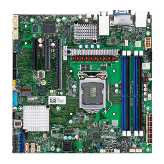
Page 11: Board Image
2.1 Board Image S5560GM2NRE-2T-HE http://www.tyan.com... - Page 12 S5560GM2NRE-2T This picture is representative of the latest board revision available at the time of publishing. The board you receive may not look exactly like the above picture. http://www.tyan.com...
-
Page 13: Block Diagram
2.2 Block Diagram S5560 Block Diagram http://www.tyan.com... -
Page 14: Motherboard Mechanical Drawing
2.3 Motherboard Mechanical Drawing http://www.tyan.com... -
Page 15: Board Parts, Jumpers And Connectors
The board you receive may not look exactly like the above diagram. The DIMM slot numbers shown above can be used as a reference when reviewing the DIMM population guidelines shown later in the manual. For the latest board revision, please visit our web site at http://www.tyan.com. http://www.tyan.com... - Page 16 4.SMBUS_VR(PJ1) 23. SATA5/SATADOM2(J8) 5.LAN1,LAN2(J11) 24. SATA4/SATADOM1(J7) 6.USB2.0(J15) 25. SPI TPM (J28) 7.USB3.2 Gen2 TYPE C (J2) 26. TYAN Debug Card Header (J66) 27. SFF-8654(38 Circuit) 8.BMC (U37) Connector(CN3) 9.COM1 (J59) 28. Mini SAS HD SATA [0:3] (J5) 10.COM2 (J64) 29. Reset Button (SW1) 11.
- Page 17 A 4-pin fan is required for fan J52: System Fan Header Signal Signal TACH1 TACH6 TACH2 TACH7 TACH3 TACH8 TACH4 TACH9 TACH5 TACH10 PWM2 PWM1 TACH11 SMB_DATA TACH12 SMB_CLK P3V3_AUX PWM3 J10: SSATA SGPIO Header Signal Signal SD1/SDO1 SDO0 SLOAD SCLOCK V3AUX HDD_FAULT http://www.tyan.com...
- Page 18 J7, J8: SATA DOM Connectors (SATA4, SATA5) Name TYPE Connects to the Serial ATA ready drives via the Serial ATA cable. J24: IPMB Connector Signal Signal IPMB_DAT IPMB_CLK VCC3_AUX J63: BMC Debug Header Signal UART_TXD UART_RXD J59/J64: COM1/COM2 Header Signal Signal http://www.tyan.com...
- Page 19 RXA0_DP TXA0_DP RXA0_DN TXA0_DN RXA1_DP RXA1_DN TXA1_DP TXA1_DN PD to GND SGPIO CLOCK SGPIO SGPIO LOAD DATAOUT PD to GND PU to P3V3 CONTROLLER_TYPE RXA2_DP TXA2_DP RXA2_DN TXA2_DN RXA3_DP TXA3_DP RXA3_DN TXA3_DN J45: PSMI Connector Signal PSMI_CLK PSMI_DAT PSMI_ALERT http://www.tyan.com...
- Page 20 P0_N P0_P OC_N P1_P P1_N P1_TX_P P1_TX_N P1_RX_P P1_RX_N J19: USB2.0 Connector Signal Signal P5V_AUX_TYPEA USB2_PCH_P9_ESD_DP USB2_PCH_P9_ESD_DN J66: TYAN Debug Card Header Signal Signal P3V3_AUX ESPI_CS0_N ESPI_IO0 ESPI_IO1 RST_ESPI_RESET_N ESPI_IO2 ESPI_IO3 CLK_66M_24M_ESPI IRQ_ESPI_ALERT0_N ID LED_BTN1: Rear IDLED Button Signal Signal...
- Page 21 PE_RX_1_N PE_RX_1_P PE_TX_1_N PE_TX_1_P DEVSLP SMB_M2_SSD_P1V8_SCL PE_RX_0_N SMB_M2_SSD_P1V8_SDA IRQ_SMB_M2_SSD_ALERT_P1 PE_RX_0_P V8_N PE_TX_0_N PERST# PE_TX_0_P CLKREQ# PEWAKE# REF_CLK_N REF_CLK_P KEY PIN KEY PIN KEY PIN KEY PIN KEY PIN KEY PIN KEY PIN KEY PIN CLK_33K PEDET P3V3 P3V3 P3V3 http://www.tyan.com...
- Page 22 J60: Intruder Header Signal PCH_INTRUDER_N Normal (Default) 1-2: Chassis Cover is Removed <Default> W/O Jumper: Chassis Cover IS Closed J1: Flash Security Override Jumper 1-2: Flash Security Override Disable<Default> Normal (Default) 2-3: Flash Security Override enable http://www.tyan.com...
-
Page 23: Installing The Processor And Heatsink
2.5 Installing the Processor and Heatsink The types of processors supported by the S5560 are listed in the 1.2 Hardware Specifications section on page 4. Check our website at http://www.tyan.com ® the latest list of validated Intel processors for this specific motherboard. - Page 24 Open the CPU socket cover. Install the processor and make sure the gold arrow is located in the right direction. Close the CPU socket cover. Close the socket lever. http://www.tyan.com...
- Page 25 The following diagram illustrates how to install the heat sink for the (LGA1200) socket. Apply the thermal grease. Place the heat sink on top of the CPU and push the 4 latches in a diagonal pattern to lock it in place. http://www.tyan.com...
- Page 26 Secure the heat sink screws. Connect the fan cable to complete the installation. http://www.tyan.com...
-
Page 27: Tips On Installing Motherboard In Chassis
Be especially careful to look for extra stand-offs. If there are any stand-offs present that are not aligned with a mounting hole on the motherboard, it will likely short components on the back of the motherboard when installed. This will cause malfunction and/or damage to your motherboard. http://www.tyan.com... - Page 28 Some chassis include plastic studs instead of metal. Although the plastic studs are usable, MiTAC recommends using metal studs with screws that will fasten the motherboard more securely in place. Below is a chart detailing what the most common motherboard studs look like and how they should be installed. http://www.tyan.com...
-
Page 29: Installing The Memory
2.7 Installing the Memory Before installing memory, ensure that the memory you have is compatible with the motherboard and processor. Check the TYAN Web site at http://www.tyan.com details of the type of memory recommended for your motherboard. Supports up to 128GB DDR4 Unbuffered ECC UDIMM 3200 memory ... - Page 30 NOTE: 1.Supported DDR4(ECC and Non-ECC)UDIMM. 2. The memory slots of DDR4 channels should be populated on a farthest first fashion. This means that blue connector cannot be populated if black is empty. 3. √ indicates a populated DIMM slot. http://www.tyan.com...
- Page 31 Memory Installation Procedure Follow these instructions to install memory modules into the S5560. Unlock a DIMM socket by Press the retaining clip outwardly in the following illustration. Align the memory module with the socket,such that the DIMM NOTCH match the KEY SLOT on the socket.
-
Page 32: Attaching Drive Cables
2.8 Attaching Drive Cables Attaching SATA Cables S5560 is equipped with Four (4) Serial ATA (SATA) channel. Connections for the drives are very simple. There is no need to set Master/Slave jumpers on SATA drives. If you are in need of SATA/SAS cables or power adapters please contact your place of purchase. -
Page 33: Installing Add-In Cards
Doing so allows air to circulate within the chassis more easily, thus improving cooling for all installed devices. NOTE: You must always unplug the power connector from the motherboard before performing system hardware changes to avoid damaging the board or expansion device. http://www.tyan.com... -
Page 34: Connecting External Devices
Linked 10 Mbps Active Green Blinking Link Green Solid On Green Solid On Linked at 100 Mbps Active Green Blinking Green Solid On Link Green Solid On Amber Solid On Linked at 1Gbps Green Blinking Amber Solid On Active No Link http://www.tyan.com... - Page 35 (Link/Activity) (Speed) No Link Link Solid Green Solid Green 100 Mbps Active Blinking Green Solid Green Link Solid Green Solid Yellow 1000 Mbps Active Blinking Green Solid Yellow Link Solid Yellow Solid Yellow (10Gbps) Active Blinking Yellow Solid Yellow http://www.tyan.com...
-
Page 36: Installing The Power Supply
2.11 Installing the Power Supply There are Two (2) power connectors on your S5560 motherboard. The S5560 supports EPS 12V power supply. J46: ATX 24-Pin Power Connector Signal Signal +3.3 Vdc +3.3 Vdc +3.3 Vdc -12 Vdc +5 Vdc PS_ON#... -
Page 37: Chapter 3: Bios Setup
Select the previous or next value/setting of the field <ESC> Exit current menu <F1> General help <F2> Previous values <F3> Load the Optimal default configuration values of the menu <F4> Save and exit <PgUp> / <PgDn> Move cursor to next/previous page http://www.tyan.com... - Page 38 BIOS menus are continually changing due to continual BIOS updates over the product lifespan of the motherboard. The BIOS menus provided are current as of the date when this manual was written. Please visit TYAN’s website at http://www.tyan.com for information on BIOS updates available for this specific motherboard.
-
Page 39: Main Menu
It displays BIOS related information. Memory Information This displays the total memory size. Access Level Read only. System Date Adjust the system date. MM (Months): DD (Days): YYYY (Years) System Time Adjust the system clock. HH (24 hours format): MM (Minutes): SS (Seconds) http://www.tyan.com... -
Page 40: Advanced Menu
Enable system to wake from S5 using RTC alarm. Serial Port Console Redirection Serial Port Console Redirection USB Configuration USB Configuration Parameters. Onboard Device Configuration Onboard Device and Function Configuration. AST2600 Super IO Configuration System Super IO Chip Parameters http://www.tyan.com... - Page 41 Tls Auth Configuration Press <Enter> to select Tls Auth Configuration. iSCSI Configuration Configure the iSCSI parameters. MAC: XXXXXXXXXXXX --- IPV4 Network Configuration Configure network parameters. (MAC: XXXXXXXXXXXX) MAC: XXXXXXXXXXXX --- IPV6 Network Configuration Configure IPV6 network parameters. (MAC: XXXXXXXXXXXX) http://www.tyan.com...
- Page 42 Enable Ipv4 HTTP Boot Support. If disabled IPV4 HTTP boot option will not be created. Disabled / Enabled Ipv6 PXE Support Enable Ipv6 PXE Boot Support. If disabled IPV6 PXE boot option will not be created. Disabled / Enabled http://www.tyan.com...
- Page 43 Enable Ipv6 HTTP Boot Support. If disabled IPV6 HTTP boot option will not be created. Disabled / Enabled PXE boot wait time Wait time to press ESC key to abort the PXE boot. Media detect count Number of times presence of media will be checked. http://www.tyan.com...
- Page 44 When set to [Fixed Time] , wake up hour Select 0-23 for example enter 8 for 3am and 15 for 3pm wake up minute Select 0-59 wake up second Select 0-59 When set to [Dynamic Time] , Wake up minute increase http://www.tyan.com...
- Page 45 Console Redirection Settings The settings specify how the host computer (which the user is using) will exchange data. Both computers should have the same or compatible settings. NOTE: Console Redirection Settings menu only available when Console Redirection was set to [Enabled]. http://www.tyan.com...
- Page 46 Bits per Second Select serial port transmission speed. The speed must be matched on the other side. Long or noisy lines may require lower speeds. 38400 / 9600 / 19200 / 115200 / 57600 Data Bits 8 / 7 http://www.tyan.com...
- Page 47 With this mode enabled only text will be sent. This is to capture Terminal data. Disabled / Enabled Resolution 100x31 Enable or disable extended terminal resolution. Disabled / Enabled Putty KeyPad Select FunctionKey and KeyPad on Putty. VT100 / LINUX / XTERMR6 / SCO / ESCN / VT400 http://www.tyan.com...
- Page 48 Bits per Second Select serial port transmission speed. The speed must be matched on the other side. Long or noisy lines may require lower speeds. 38400 / 9600 / 19200 / 115200 / 57600 Data Bits 8 / 7 http://www.tyan.com...
- Page 49 With this mode enabled only text will be sent. This is to capture Terminal data. Disabled / Enabled Resolution 100x31 Enable or disable extended terminal resolution. Disabled / Enabled Putty KeyPad Select FunctionKey and KeyPad on Putty. VT100 / LINUX / XTERMR6 / SCO / ESCN / VT400 http://www.tyan.com...
- Page 50 VT-UTF8 / VT100 / VT100+ / ANSI Bits per Second EMS Select serial port transmission speed. The speed must be matched on the other side. Long or noisy lines may require lower speeds. 115200 / 9600 / 19200 / 38400 / 57600 http://www.tyan.com...
- Page 51 ‘start’ signal can be sent to restart the flow. Hardware flow control uses two wires to send start/stop signal. None / Hardware RTS/CTS / Software Xon/Xoff Data Bits EMS / Parity EMS / Stop Bits EMS Read only. http://www.tyan.com...
- Page 52 USB Mass Storage Driver Support Enable/Disable USB Mass Storage Driver Support. Disabled / Enabled Port 60/64 Emulation Enables I/O Port 60h/64h emulation support. This should be enabled for the complete USB keyboard legacy support for non-USB aware OSes. Disabled / Enabled http://www.tyan.com...
- Page 53 Mass storage device emulation type. ‘Auto’ enumerates devices according to their media format. Optical drives are emulated as ‘CDROM’, drives with no media will be emulated according to a drive type. Auto / Floppy / Forced FDD / Hard Disk / CD-ROM http://www.tyan.com...
- Page 54 Enabled / Disabled LAN1 LAN Enable/Disable control function. Enabled / Disabled LAN2 LAN Enable/Disable control function. Enabled / Disabled Chassis Intrusion Detection Enabled: When a chassis open event is detected, the BIOS will display the event. Enabled / Disabled http://www.tyan.com...
- Page 55 3.3.6 AST2600 Device Configuration Serial Port 1 Configuration Set Parameters of Serial Port 1 (COMA) Serial Port 2 Configuration Set Parameters of Serial Port 2 (COMB) http://www.tyan.com...
- Page 56 Enable or disable Serial Port (COM). Enabled / Disabled NOTE: The following items will appear when Serial Port set to [Enabled] Change Settings Select an optimal settings for Super IO Device. Auto / IO=3F8h; IRQ=4; / IO=2F8h; IRQ=4; / IO=3F8h; IRQ=4; / IO=2E8h; IRQ=4; http://www.tyan.com...
- Page 57 3.3.6.2 Serial Port 2 Configuration Serial Port Enable or disable Serial Port (COM). Enabled / Disabled Change Settings Select an optimal setting for Super IO Device. Auto / IO=2F8h; IRQ=3; / IO=3F8h; IRQ=3; / IO=3E8h; IRQ=3; / IO=2E8h; IRQ=3; http://www.tyan.com...
- Page 58 PWM Minimal Duty Cycle PWM Minimal Duty Cycle (%). NOTE: This item is available when Fan Speed Control is set to [Manual]. BMC Alert Beep Enable/Disable BMC Alert Beep. On / Off PMBus Support PMBus Support. Enabled / Disabled http://www.tyan.com...
- Page 59 Number of PSU Number of PSU 1 / 2 3.3.7.1 Sensor Data Register Monitoring When you enter the Sensor Data Register Monitoring submenu, you will see the following dialog window pop out. NOTE 1: SDR can not be modified. Read only. http://www.tyan.com...
- Page 60 http://www.tyan.com...
- Page 61 3.3.8 Trusted Computing Security Device Support Enable or Disable BIOS support for security device. O.S. will not show Security device. O.S. will not show Security Device. TCG EFI protocol and INT1A interface will not be available. Enable / Disable http://www.tyan.com...
- Page 62 3.3.9 NVMe Configuration http://www.tyan.com...
- Page 63 3.3.10 PCI Subsystem Above 4G Decoding Enables or Disables 64bit capable Devices to be decoded in Above 4G Address Space (Only if System supports 64 bit PCI Decoding). Disabled / Enabled http://www.tyan.com...
- Page 64 3.3.10.1 PCI Express Settings Maximum Payload Set Maximum Payload of PCI Express Device or allow System BIOS to select the value. Auto / 128 Bytes / 256 Bytes / 512 Bytes / 1024 Bytes / 2048 Bytes / 4096 Bytes http://www.tyan.com...
- Page 65 Enable or Disable Option ROM execution for selected Slot. Disabled / Enabled PCIE#2 Option ROM Enable or Disable Option ROM execution for selected Slot. Disabled / Enabled PCIE#3 Option ROM Enable or Disable Option ROM execution for selected Slot. Disabled / Enabled http://www.tyan.com...
- Page 66 3.3.12 Redfish Host Interface Configuration Redfish Enable/Disable AMI Redfish. Enabled Disabled Authentication mode Select authentication mode Basic Authentication / Session Authentication IP address Enter IP address IP Mask address Enter IP Mask address IP Port Enter IP Port http://www.tyan.com...
- Page 67 3.3.13 Tls Auth Configuration Server CA Configuration Press <Enter> to configure Server CA. Client Cert Configuration Press <Enter> to configure Client Cert. http://www.tyan.com...
- Page 68 3.3.13.1 Server CA Configuration Enroll Cert Press <Enter> to enroll cert. Delete Cert Press <Enter> to delete cert. http://www.tyan.com...
- Page 69 3.3.13.1.1 Enroll Cert Enroll Cert Using File Enroll Cert Using File. Cert GUID Input digit character in 11111111-2222-3333-4444-1234567890ab format. Commit Changes and Exit Commit Changes and Exit. Discard Changes and Exit Discard Changes and Exit. http://www.tyan.com...
- Page 70 3.3.13.1.2 Delete Cert FE9C6606-8B49-44A3-8B6B-DEA3A0E032 GUID for CERT. Disabled / Enabled http://www.tyan.com...
- Page 71 3.3.14 iSCSI Configuration Attempt Priority Change the priority using +/- keys. Use arrow keys to select the attempt then press+/- to move the attempt up/down in the attempt order list. Host iSCSI Configuration Host iSCSI Configuration http://www.tyan.com...
- Page 72 Change the priority using +/- keys. Use arrow keys to select the attempt then press +/- to move the attempt up/down in the attempt order lists. Host Attempt / Redfish Attempt Commit Changes and Exit Commit Changes and Exit http://www.tyan.com...
- Page 73 IPv4 Delete Attempts Delete one or more attempts. Change Attempt Order Change the order of Attempts using +/- keys. Use arrow keys to select the attempt then press +/- to move the attempt up/down in the attempt order list. http://www.tyan.com...
- Page 74 3.3.14.2.1 Add an Attempt ® MAC xx:xx:xx:xx:xx:xx (Intel Ethernet Converged Network Connection) PFA: Bus 1 / Dev 0 / Func 0. http://www.tyan.com...
- Page 75 Initiator IP address is system assigned in IP6 mode. In Autoconfigure mode, iSCSI driver will attempt to connect iSCSI target via IPv4 stack, if failed then attempt IPv6 stack. IPv4 / IPv6 / Autoconfigure Connection Retry Count The minimum value is 0 and the maximum is 16. 0 means no retry. http://www.tyan.com...
- Page 76 Hexadecimal representation of the LU number. Examples are: 4752-3A4F-6b7e- 3F99, 6734-9-156f-127, 4186-9. Authentication Type Authentication method: CHAP, Kerberos, or None. CHAP / None Save Changes Must reboot system manually for changes to take place. Back to Previous Page Back to Previous Page. http://www.tyan.com...
- Page 77 Initiator IP address is system assigned in IP6 mode. In Autoconfigure mode, iSCSI driver will attempt to connect iSCSI target via IPv4 stack, if failed then attempt IPv6 stack. IPv4 / IPv6 / Autoconfigure Connection Retry Count The minimum value is 0 and the maximum is 16. 0 means no retry. http://www.tyan.com...
- Page 78 Get target info via DHCP Get target info via DHCP Authentication Type Authentication method: CHAP, Kerberos, or None. CHAP / None Save Changes Must reboot system manually for changes to take place. Back to Previous Page Back to Previous Page. http://www.tyan.com...
- Page 79 3.3.14.2.3 Delete Attempts Attempt 1 MAC xx:xx:xx:xx:xx:xx, PFA: Bus 1 / Dev 0 / Func 0, iSCSI mode: Enabled, IP version: IPv4. Disabled / Enabled Commit Changes and Exit Commit Changes and Exit. Discard Changes and Exit Discard Changes and Exit. http://www.tyan.com...
- Page 80 Change the order of Attempts using +/- keys. Use arrow keys to select the attempt then press +/- to move the attempt up/down in the attempt order list. Attempt 1 Commit Changes and Exit Commit Changes and Exit. Discard Changes and Exit Discard Changes and Exit. http://www.tyan.com...
- Page 81 3.3.15 MAC:xxxxxxxxxxxx - IPv4 Network Configuration Configured Indicate whether network address configured successfully or not. Disabled / Enabled Save Changes and Exit Save Changes and Exit. http://www.tyan.com...
- Page 82 3.3.16 MAC:xxxxxxxxxxxx - IPv6 Network Configuration Enter Configuration Menu Press ENTER to enter configuration menu for IPv6 configuration. http://www.tyan.com...
- Page 83 Duplicate Address Detection on a tentative address. A value of zero indicates that Duplicate Address Detection is not performed. Policy Automatic or manual. Automatic / Manual NOTE: The Advanced Configuration submenu is available when Policy is set to [Manual]. Save Changes and Exit Save Changes and Exit. http://www.tyan.com...
- Page 84 DNS addresses can only be configured under manual policy. e.g.2002::4. Separate the IP address with blank space to configure more than one address. Commit Changes and Exit Commit Changes and Exit Discard Changes and Exit Discard Changes and Exit http://www.tyan.com...
- Page 85 3.3.17 Intel® Ethernet Converged Network Adapter X550-T2 Configuration Firmware Image Properties View device firmware version information. NIC Configuration Click to configure the network device port. Blink LEDs Blink LEDs for a duration up to 15 seconds. http://www.tyan.com...
- Page 86 3.3.17.1 Firmware Image Properties Configuration http://www.tyan.com...
- Page 87 Enables power on of the system via LAN. Note that configuring Wake on LAN in the operating system does not change the value of this setting, but does override the behavior of Wake on LAN in OS controlled power states. Disabled / Enabled http://www.tyan.com...
-
Page 88: Cpu Menu
3.4 CPU Menu CPU Configuration CPU Configuration Parameters CPU – Power Management Control CPU – Power Management Control Options http://www.tyan.com... - Page 89 All / 1 / 2 / 3 / 4 / 5 / 6 / 7 Enable Intel® TXT Enable Intel® TXT. Disabled / Enabled Intel (VMX) Virtualization Technology When enabled, a VMM can utilize the additional hardware capabilities provided by Vanderpool Technology. Disabled / Enabled http://www.tyan.com...
- Page 90 Enables Txt Alias Checking capability Changes require full Txt capability before it will take effect. It is a one time only change, next reboot will be reset. DPR Memory Size(MB) Reserve DPR memory size (0-255) MB. SGX settings SGX settings http://www.tyan.com...
- Page 91 No Change in Owner EPOCHs / Change to New Random Owner EPOCHs / Manual User Defined Owner SGX Launch Control Policy Software Guard Extensions (SGX) Launch Control Policy. Options are: Intel Locked – Select Intel’s Launch Enclave. Unlocked – Enable OS/VMM configuration of Launch Enclave. http://www.tyan.com...
- Page 92 Intel Speed Shift Technology Enable/Disable Intel® Speed Shift Technology support. Enabling will expose the CPPC v2 interface to allow for hardware controlled P-states. Disabled / Native Mode / Out of Band Mode Intel SpeedStep Enable/Disable Intel SpeedStep Disabled / Enabled http://www.tyan.com...
- Page 93 Maximum Package C state Limit Setting. CPU Default: Leaves to Factory default value. Auto: Initializes to deepest available Package C State Limit. C0/C1 /C2 / C3 / C6 / C7 / C7S / C8 / C9 /C10/ Cpu Default / Auto http://www.tyan.com...
-
Page 94: Chipset Menu
3.5 Chipset Menu North Bridge System Agent(SA) parameters. South Bridge PCH parameters. http://www.tyan.com... - Page 95 3.5.1 North Bridge Configuration Memory Configuration Memory Configuration Parameters Graphics Configuration Graphics Configuration DMI/OPI Configuration Control various DMI functions PCI Express Configuration PCI Express Configuration settings VT-d VT-d capability Enabled / Disabled http://www.tyan.com...
- Page 96 3.5.1.1 Memory Configuration DDR Speed Control DDR Frequency control Auto / Manual ECC Support Enable/disable DDR Ecc Support Disabled / Enabled http://www.tyan.com...
- Page 97 3.5.1.2 Graphics Configuration Primary Display Select which Graphics device should be Primary Display. Auto / IGFX / PEG / PCH PCIe Internal Graphics Enable/Disable Internal Graphics (IGFX). Auto / Disabled / Enabled http://www.tyan.com...
- Page 98 3.5.1.3 DMI/OPI Configuration DMI Max Link Speed Set DMI Speed Gen1/Gen2/Gen3 Gen1 / Gen2 / Gen3 DMI Gen3 ASPM DMI Gen3 ASPM Support Disabled / Auto / ASPM L0s / ASPM L1 / ASPM L0sL1 http://www.tyan.com...
- Page 99 3.5.1.4 PCI Express Configuration PCI Express Root Port 1~4 PCI Express Root Port Settings http://www.tyan.com...
- Page 100 Force L0s – Force all links to L0s States AUTO – BIOS auto configure DISABLE – Disables ASPM Disabled / L0s / L1 / L0sL1 PCIe Speed Configure PCIe Speed Auto / Gen1 / Gen2 / Gen3 / Gen4 http://www.tyan.com...
- Page 101 HD Audio Subsystem Configuration Settings. PCI Express Configuration PCI Express Configuration settings. Enabled / Disabled Restore AC Power Loss Select AC power state when power is re-applied after a power failure. Power On / Power Off / Last State http://www.tyan.com...
- Page 102 3.5.2.1 Server ME Configuration http://www.tyan.com...
- Page 103 AHCI / RAID Serial ATA Port0/1/2/3/4/5/6/7 Hot Plug Designates this port as Hot Pluggable. Disabled / Enabled SATA Device Type Identify the SATA port is connected to Solid State Drive or Hard disk Drive. Hard Disk Drive / Solid State Drive http://www.tyan.com...
- Page 104 3.5.3 HD Audio Configuration HD Audio Control Detection of the HD-Audio device. Disabled = HDA will be unconditionally disabled. Enabled = HDA will be unconditionally enabled. Disabled / Enabled http://www.tyan.com...
- Page 105 3.5.4 PCI Express Configuration DMI Link ASPM Control The control of Active State Power Management of the DMI Link. Disabled / L0s / L1 / L0sL1 / Auto PCI Express Root Port 1/5/9/11/21 PCI Express Root Port Settings http://www.tyan.com...
- Page 106 Control the PCI Express Root Port. Disabled / Enabled ASPM Set the ASPM Level: Force L0s – Force all links to L0s State AUTO – BIOS auto configure DISABLE – Disables ASPM PCIe Speed Configure PCIe Speed Auto / Gen1 / Gen2 / Gen3 http://www.tyan.com...
-
Page 107: Server Management
3 minutes / 4 minutes / 5 minutes / 6 minutes FRB-2 Timer Policy Configure how the system should respond if the FRB-2 Timer expires. Not available if FRB-2 Timer is disabled. Do Nothing / Reset / Power Down / Power Cycle http://www.tyan.com... - Page 108 Do Nothing / Reset / Power Down / Power Cycle System Event Log Press<Enter> to change the SEL event log configuration. BMC network configuration Configure BMC network parameters. BMC User Settings Press <Enter> to Add, Delete and Set Privilege level for users. http://www.tyan.com...
- Page 109 No / Yes, On next reset / Yes, On every reset Log EFI Status Codes Disable the logging of EFI Status Codes or log only error code or only progress code or both. Disabled / Both / Error code / Progress code http://www.tyan.com...
- Page 110 Management Port 2 Enable/Disable BMC Share NIC. Enabled / Disabled Configure IPV6 support Management Port 1 IPV6 Support Enable or Disable LAN1 IPV6 Support. Enabled / Disabled Management Port 2 IPV6 Support Enable or Disable LAN2 IPV6 Support. Enabled / Disabled http://www.tyan.com...
- Page 111 3.6.3 BMC User Settings Add User Press <Enter> to Add a user. Delete User Press <Enter> to Delete a user. Change User Settings Press <Enter> to change User Settings. http://www.tyan.com...
- Page 112 User Access Enable/Disable the BMC User’s Access. Enabled / Disabled Channel No Enter BMC Channel Number. N/A / 1 / 8 User Privilege Limit Enter BMC User Privilege Limit for Selected Channel. None / User / Operator / Administrator http://www.tyan.com...
- Page 113 3.6.3.2 Delete User User Name Enter BMC User Name. User Password Enter New Password to change. Password at least 8 characters. http://www.tyan.com...
- Page 114 User Access Enable/Disable the BMC User’s Access. Enabled / Disabled Channel No Enter BMC Channel Number. N/A / 1 / 8 User Privilege Limit Enter BMC User Privilege Limit for Selected Channel. None / User / Operator / Administrator http://www.tyan.com...
-
Page 115: Security
3.7 Security Administrator Password Set Administrator Password. User Password Set User Password. Security Frozen Mode Enable or disable HDD security freeze lock. Disable to support secure erase function. Disabled / Enabled Secure Boot Customizable Secure Boot settings http://www.tyan.com... - Page 116 Standard / Custom Restore Factory Keys Force System to User Mode. Install factory default Secure Boot key databases Reset To Setup Mode Delete all Secure Boot Key databases from NVRAM Key Management Enables experienced users to modify Secure Boot variables http://www.tyan.com...
- Page 117 Copy NVRAM content of Secure Boot variable to files in a root folder on a file system device Enroll Efi Image Allow the image to run in Secure Boot mode. Enroll SHA256 Hash certificate of a PE image into Authorized Signature Database(db) http://www.tyan.com...
- Page 118 Enroll factory Defaults or load the keys from a file with: 1. Public Key Certificate in: a) EFI_SIGNATURE_LIST b) EFI_CERT_X509 (DER encoded) c) EFI_CERT_RSA2048 (bin) d) EFI_CERT_SHA256 (bin) 2. Authenticated UEFI Variable Key: Vendor, Custom, Mixed, Test (*) modified from Setup menu Set New Key Append Key http://www.tyan.com...
- Page 119 Enroll factory Defaults or load the keys from a file with: 1. Public Key Certificate in: a) EFI_SIGNATURE_LIST b) EFI_CERT_X509 (DER encoded) c) EFI_CERT_RSA2048 (bin) d) EFI_CERT_SHA256 (bin) 2. Authenticated UEFI Variable Key: Vendor, Custom, Mixed, Test (*) modified from Setup menu Set New Key Append Key http://www.tyan.com...
-
Page 120: Boot
Wait For “ESC” If Error Wait for “ESC” key to be pressed if error occurs. Disabled / Enabled Endless Boot Continuously searches for the Legacy PXE boot image until it is found or the process is aborted (press Ctrl+Alt+Del). Disabled / Enabled http://www.tyan.com... - Page 121 Remove an EFI boot option from the boot order 3.8.1 Add New Boot Option Configuration Add boot option Specify name for new boot option Path for boot option Enter the path to the boot option in the format fsx:\path\filename.efi Create Create the newly formed boot option http://www.tyan.com...
- Page 122 3.8.2 Delete Boot Option Configuration Delete Boot Option Sets the system boot order. Select one to Delete/ Device Name http://www.tyan.com...
-
Page 123: Save & Exit
Reset the system after saving the changes. Discard Changes and Reset Reset system setup without saving any changes. Save Changes Save changes done so far to any of the setup options. Discard Changes Discard changes done so far to any of the setup options. http://www.tyan.com... - Page 124 Restore Defaults Restore/Load Default values for all the setup options. Save as User Defaults Save the changes done so far as User Defaults. Restore User Defaults Restore the User Defaults to all the setup options. Boot Override Device Name http://www.tyan.com...
-
Page 125: Chapter 4: Diagnostics
BIOS flash failure, you must contact your dealer for a replacement BIOS. There are no exceptions. TYAN does not have a policy for replacing BIOS chips directly with end users. In no event will TYAN be held responsible for damages done by the end user. -
Page 126: Amibios Post Code (Aptio)
4.2 AMIBIOS Post Code (Aptio) The POST code checkpoints are the largest set of checkpoints during the BIOS pre- boot process. The following table describes the type of checkpoints that may occur during the POST portion of the BIOS: Checkpoint Ranges Status Code Range Description 0x01 –... - Page 127 SEC Error Codes 0x0C – 0x0D Reserved for future AMI SEC error codes 0x0E Microcode not found 0x0F Microcode not found PEI Phase Status Code Description Progress Codes 0x10 PCI Core is started 0x11 Pre-memory CPU initialization is started 0x12 Pre-memory CPU initialization (CPU module specific) 0x13 Pre-memory CPU initialization (CPU module specific)
- Page 128 Status Code Description Post-Memory North Bridge initialization (North Bridge module 0x38 specific) Post-Memory North Bridge initialization (North Bridge module 0x39 specific) Post-Memory North Bridge initialization (North Bridge module 0x3A specific) 0x3B Post-Memory South Bridge initialization is started Post-Memory South Bridge initialization (South Bridge module 0x3C specific) Post-Memory South Bridge initialization (South Bridge module...
- Page 129 Status Code Description 0xEB S3 OS wake error 0xEC – 0xEF Reserved for future AMI error codes Recovery Progress Codes 0xF0 Recovery condition triggered by firmware (Auto recovery) 0xF1 Recovery condition triggered by user (forced recovery) 0xF2 Recovery process started 0xF3 Recovery firmware image is found.
- Page 130 Status Code Description 0x74 South Bridge DXE initialization (South Bridge module specific) 0x75 South Bridge DXE initialization (South Bridge module specific) 0x76 South Bridge DXE initialization (South Bridge module specific) 0x77 South Bridge DXE initialization (South Bridge module specific) 0x78 ACPI module initialization 0x79 CSM initialization...
- Page 131 Status Code Description 0xAD Ready To Boot event 0xAE Legacy Boot event 0xAF Exit Boot Services event 0xB0 Runtime Set Virtual Address MAP Begin 0xB1 Runtime Set Virtual Address MAP End 0xB2 Legacy Option ROM initialization 0xB3 System Reset 0xB4 USB hot plug 0xB5 PCI bus hot plug...
- Page 132 Status Code Description 0xDD00 MRC initialization start 0xDD02 Safe Mode Override 0xDD03 MRC Early Overrides 0xDD09 DDRIO Config - Pre DCC 0xDD89 DDRIO Config - Pre DCC Error 0xDD10 2D command plot 0xDD90 2D command plot Error 0xDD11 MC Frequency Lock 0xDD91 MC Frequency Lock Error 0xDD12...
- Page 133 0xDD27 Pre-Training 0xDDA7 Pre-Training Error 0xDD28 Early Command Training 0xDDA8 Early Command Training Error 0xDD29 SenseAmp Offset Training 0xDDA9 SenseAmp Offset Training Error 0xDD2A Read MPR training 0xDDAA Read MPR training Error 0xDD2B Read Leveling training 0xDDAB Read Leveling training Error 0xDD2C Jedec Write Leveling training 0xDDAC...
- Page 134 0xDD3A Command Voltage Centering 0xDDBA Command Voltage Centering Error 0xDD3B Write Voltage Centering 2D 0xDDBB Write Voltage Centering 2D Error 0xDD3C Read Voltage Centering 2D 0xDDBC Read Voltage Centering 2D Error 0xDD3D Post training 0xDDBD Post training Error 0xDD3E Late command training 0xDDBE Late command training Error 0xDD3F...
- Page 135 0xDD4E Write Leveling FlyBy training 0xDDCE Write Leveling FlyBy training Error 0xDD4F MRC Comp override 0xDDCF MRC Comp override Error 0xDD50 MRC activate 0xDDD0 MRC activate Error 0xDD51 Row Hammer Prevention 0xDDD1 Row Hammer Prevention Error 0xDD52 Get MRC Data 0xDDD2 Get MRC Data Error 0xDD53...
- Page 136 0xDD62 ClkTCO Comp Training 0xDDE2 ClkTCO Comp Training Error 0xDD63 Read Per Bit Deskew Calibration 0xDDE3 Read Per Bit Deskew Calibration Error 0xDD64 Sense amplifier offset correction 0xDDE4 Sense amplifier offset correction Error 0xDD65 DCC Replica 0xDDE5 DCC Replica Error 0xDD66 DCC Finalization 0xDDE6...
- Page 137 UEFI recovery bootloader that would prevent the recovery process itself from working. In no event shall Tyan be liable for direct, indirect, incidental, special or consequential damages arising from the BIOS update or recovery.
- Page 138 “Flash update completed. Press any key to reset the system” displayed on screen. 8.Remove the USB disk and reboot. If your system does not have video output or the POST code halts at “FF” on the right-lower portion of the screen, please contact Tyan representatives for RMA service.
- Page 139 Appendix II: Fan and Temp Sensors This section aims to help readers identify the locations of some specific FAN and Temp Sensors on the motherboard. A table of BIOS Temp sensor name explanation is also included for readers’ reference. NOTE: The red dot indicates the sensor.
- Page 140 BIOS Temp Sensor Name Explanation:...
- Page 141 CPU_DTS_Temp Temperature of the CPU Digital Temperature Sensor PCH_Temp Temperature of the PCH_Temp Area DIMM_Area Temperature of the DIMM_Area P0_MC0_DIM_CH_A Temperature of P0_MC0_DIM_CH_A Slot P0_MC0_DIM_CH_B Temperature of P0_MC0_DIM_CH_B Slot P_MOSFET Temperature of the CPU _MOSFET SYS_Air_Inlet Temperature of the SYS_Air_Inlet Area SYS_Air_Outlet Temperature of the SYS_Air_Outlet Area MB_Air_Inlet...
- Page 142 NOTE...
-
Page 143: Glossary
Glossary ACPI (Advanced Configuration and Power Interface): a power management specification that allows the operating system to control the amount of power distributed to the computer’s devices. Devices not in use can be turned off, reducing unnecessary power expenditure. AGP (Accelerated Graphics Port): a PCI-based interface which was designed specifically for demands of 3D graphics applications. - Page 144 Bus: a data pathway. The term is used especially to refer to the connection between the processor and system memory, and between the processor and PCI or ISA local buses. Bus mastering: allows peripheral devices and IDEs to access the system memory without going through the CPU (similar to DMA channels).
- Page 145 ROM chip which can, unlike normal ROM, be updated. This allows you to keep ’s ® up with changes in the BIOS programs without having to buy a new chip. TYAN BIOS updates can be found at http://www.tyan.com ESCD (Extended System Configuration Data): a format for storing information about Plug-n-Play devices in the system BIOS.
- Page 146 IRQ (Interrupt Request): an electronic request that runs from a hardware device to the CPU. The interrupt controller assigns priorities to incoming requests and delivers them to the CPU. It is important that there is only one device hooked up to each IRQ line;...
- Page 147 not stripe. RAID level 1 also allows for faster access time and fault-tolerance, since either hard drive can be read at the same time. RAID level 0+1 is striping and mirroring, providing fault-tolerance, striping, and faster access all at the same time. RAIDIOS: RAID I/O Steering (Intel) RAM (Random Access Memory): technically refers to a type of memory where any byte can be accessed without touching the adjacent data and is often referred to the...
- Page 148 USB (Universal Serial Bus): a versatile port. This one port type can function as a serial, parallel, mouse, keyboard or joystick port. It is fast enough to support video transfer, and is capable of supporting up to 127 daisy-chained peripheral devices. VGA (Video Graphics Array): the PC video display standard V-SYNC: controls the vertical scanning properties of the monitor.
-
Page 149: Technical Support
"TYAN's tech support is some of the most impressive we've seen, with great response time and exceptional organization in general" - Anandtech.com Help Resources: 1. See the beep codes section of this manual. - Page 150 Return Merchandise Authorization (RMA) number. The RMA number Should be prominently displayed on the outside ® of the shipping carton and the package should be mailed prepaid. TYAN will pay to have the board shipped back to you.
Need help?
Do you have a question about the S5560 and is the answer not in the manual?
Questions and answers