Table of Contents
Advertisement
Quick Links
Copyright
Copyright © 2023 MiTAC International Corporation. All rights reserved. No part of
this manual may be reproduced or translated without prior written consent from
MiTAC International Corporation.
Trademark
All registered and unregistered trademarks and company names contained in this
manual are property of their respective owners including, but not limited to the
following.
TYAN
®
is a trademark of MiTAC International Corporation.
®
Intel
is a trademark of Intel
AMI, AMI BIOS are trademarks of AMI Technologies.
®
Microsoft
, Windows
®
Winbond
is a trademark of Winbond Electronics Corporation.
Notice
Information contained in this document is furnished by MiTAC International
Corporation and has been reviewed for accuracy and reliability prior to printing.
MiTAC assumes no liability whatsoever, and disclaims any express or implied
warranty, relating to sale and/or use of TYAN
warranties relating to fitness for a particular purpose or merchantability. MiTAC
retains the right to make changes to product descriptions and/or specifications at
any time, without notice. In no event will MiTAC be held liable for any direct or
indirect, incidental or consequential damage, loss of use, loss of data or other
malady resulting from errors or inaccuracies of information contained in this
document.
S5652
Version 1.0h
®
Corporation.
®
are trademarks of Microsoft Corporation.
http://www.tyan.com
®
products including liability or
1
Advertisement
Table of Contents

Related Manuals for TYAN S5652


Summary of Contents for TYAN S5652
- Page 1 Corporation and has been reviewed for accuracy and reliability prior to printing. MiTAC assumes no liability whatsoever, and disclaims any express or implied ® warranty, relating to sale and/or use of TYAN products including liability or warranties relating to fitness for a particular purpose or merchantability. MiTAC retains the right to make changes to product descriptions and/or specifications at any time, without notice.
-
Page 2: Table Of Contents
4.2 AMIBIOS Post Code (Aptio) ............182 Appendix I: How to recover UEFI BIOS ..........189 Appendix II: Fan and Temp Sensors ............ 191 Appendix III: PCIE Bus Number ............195 Glossary ....................196 Technical Support .................. 202 http://www.tyan.com... - Page 3 http://www.tyan.com...
- Page 4 MCC CPU Carrier x1 SATA Single Cable x 2 Rear IO shielding x 1 S5652 Quick Installation Guide x 1 M.2 Standoff & Screw x 3 IMPORTANT NOTE: Sales samples may not come with any of the accessories listed above.
-
Page 5: Chapter 1: Instruction
PCI-E bus implementation. The S5652 not only empowers you in today’s demanding IT environment but also offers a smooth path for future application upgradeability. All of these rich feature sets provide the S5652 with the power and flexibility to meet demanding requirements for today’s IT environments. - Page 6 AST2600 iKVM Feature 24-bit high quality video compression / Supports storage over IP and remote platform-flash / USB Server 2.0 virtual hub Management AST2600 IPMI Feature IPMI 2.0 compliant baseboard management controller (BMC) / 10/100/1000 Mb/s MAC interface BIOS Brand / ROM size AMI / 32MB http://www.tyan.com...
- Page 7 90%, non-condensing at 35° C Humidity RoHS RoHS 6/6 Compliant Operating OS supported list Please refer to our AVL support lists. System Motherboard (1) S5652 Motherboard Manual (1) Quick Installation Guide Package Contains I/O Shield (1) I/O Shield Cable SATA (2) SATA signal cables...
- Page 8 Onboard Aspeed AST2600 AST2600 iKVM Feature 24-bit high quality video compression / Supports storage over IP and remote platform-flash / USB Server 2.0 virtual hub Management AST2600 IPMI Feature IPMI 2.0 compliant baseboard management controller (BMC) / 10/100/1000 Mb/s MAC interface http://www.tyan.com...
-
Page 9: Software Specifications
Package Contains I/O Shield (1) I/O Shield Cable SATA (2) SATA signal cables 1.3 Software Specifications For the latest AST2600 User’s Guide and OS (operation system) support, please visit the Tyan’s Web site at http://www.tyan.com for the latest information http://www.tyan.com... -
Page 10: Chapter 2: Board Installation
Caution! To avoid damaging the motherboard and associated components, do not use torque force greater than 5~7kgf/cm (4.35~6.09 lb/in) on each mounting screw for motherboard installation. Do not apply power to the board if it has been damaged. http://www.tyan.com... -
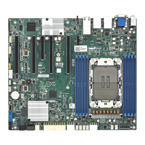
Page 11: Board Image
2.1 Board Image S5652AGM3NRE-2T This picture is representative of the latest board revision available at the time of publishing. The board you receive may not look exactly like the above picture. http://www.tyan.com... -
Page 12: Block Diagram
2.2 Block Diagram S5652AGM3NRE-2T http://www.tyan.com... - Page 13 S5652AGMNRE http://www.tyan.com...
-
Page 14: Motherboard Mechanical Drawing
2.3 Motherboard Mechanical Drawing http://www.tyan.com... -
Page 15: Board Parts, Jumpers And Connectors
The board you receive may not look exactly like the above diagram. The DIMM slot numbers shown above can be used as a reference when reviewing the DIMM population guidelines shown later in the manual. For the latest board revision, please visit our web site at http://www.tyan.com. http://www.tyan.com... - Page 16 D. PCI-e Gen 5 x16 FH/FL (PCIE2) B. PCI-e Gen5 x16 FH/FL (PCIE4) E. PCI-e Gen5 x16 FH/FL (PCIE1) C. PCI-e Gen5 x8 FH/FL (PCIE3) LEDs iv PLD_HB_LED (D33) i ME_LED (ME_LED) ii HDD_LED1 (HDD_LED1) v BMC_HB_LED (D1_BMC) iii IPMI_LED1 (IPMI_LED) http://www.tyan.com...
- Page 17 Use this header to connect the cooling fan to your motherboard to keep the system stable and reliable. Note: A 4-pin fan is required for fan support 4pin Control RAID KEY: SATA RAID KEY (VROC Header) Signal Signal PU_KEY_CONN_PIN2_R FM_PCH_SATA_RAID_KEY_R PSMI_HD1: PSMI Connector Signal PSMI_5V_SMBCLK PSMI_5V_SMBDATA PSU_ALERT_N P3V3 http://www.tyan.com...
- Page 18 USB3_P0_TX_FPB USB2_N1_FPB_R USB2_P1_FPB_R USB2_N0_FPB_R USB2_P0_FPB_R FAN_FP: Fan Connector (Reserved for Barebone) Signal Signal FAN_T1 FAN_T6 FAN_T2 FAN_T7 FAN_T3 FAN_T8 FAN_T4 FAN_T8 FAN_T5 FAN_T10 PWM_FRONT3 PWM_FRONT12 FAN_T11 FAN_SDA FAN_T12 FAN_SCL P3V3_AUX PWM_REAR12 P3V3_AUX FAN_T13 FAN_T15 FAN_T14 FAN_T16 PWM_BB3 PWM_6 PWM_CPU0 http://www.tyan.com...
- Page 19 SATA1_SGPIO: SGPIO Header Signal Signal SGIO_HDR_SM_CLK SGIO_HDR_SM_DAT SGPIO_SATA1_DATAOUT_R SGPIO_SATA1_LOAD_R SGPIO_SATA1_CLOCK_R DBG_LPC3 HDR_3: 7-pin NVMe Hot Plug Function Connector Signal Signal VCC3_AUX HP0_SCK HP0_SDA CPU01_SMBALERT_N_C VCC3 J6: Front Audio Header Signal Signal MIC2-L_R AGND_P5V MIC2-R_R FP_AUD_DETECT_N LINE2-R_R MIC2-JD FIO_SENSE LINE2-L_R LINE2-JD http://www.tyan.com...
- Page 20 A27 B27 CPU0_PE4_HDD0_SDA1 A28 B28 GND CLK_100M_DB2000_CPU0_N A29 B29 RST_NVME1_CPU0_PERST_N VME2_DP CLK_100M_DB2000_CPU0_N A30 B30 FM_CPU0_PE4_PRSTNB_N VME2_DN A31 B31 GND CPU0_PE4_RX_DN<1> A32 B32 CPU0_PE4_TX_DN<1> CPU0_PE4_RX_DP<1> A33 B33 CPU0_PE4_TX_DP<1> A34 B34 GND CPU0_PE4_RX_DN<0> A35 B35 CPU0_PE4_TX_DN<0> CPU0_PE4_RX_DP<0> A36 B36 CPU0_PE4_TX_DP<0> A37 B37 GND http://www.tyan.com...
- Page 21 Pin Pin Signal SPI_TPM_CONN_CLK P3V3_AUX RST_PLTRST_TPM_CONN_N FM_TPM_CONN_PRSNT_R_N SPI_TPM_CONN_MOSI IRQ_TPM_CONN_PIRQ_N SPI_TPM_CONN_MISO P3V3 SPI_PCH_TPM_CONN_CS_N NC_TPM_PIN6 FPIO_VGA3: VGA Header Signal Signal VGA2_5V HD_VGA_R HD_VGA_G HD_VGA_B HD_VGA_DAT HD_VGA_HS HD_VGA_CLK HD_VGA_VS J4: ESPI Debug Header Signal Signal P3V3_AUX DBG_ESPI_CS1_N LAD0_ESPI_DBG_IO0 LAD1_ESPI_DBG_IO1 DBG_ESPI_RESET_N LAD2_ESPI_DBG_IO2 LAD3_ESPI_DBG_IO3 CLK_DBG_ESPI DBG__ESPI_ALERT1_N http://www.tyan.com...
- Page 22 M.2#1: M.2 Socket Signal Signal P3V3 P3V3 PERN3 PERP3 I/O/LED PETN3 P3V3 PETP3 P3V3 P3V3 PERN2 P3V3 PERP2 PETN2 PETP2 PERN1 PERP1 PETN1 PETP1 M2_SMB_CLK2 PERP0/SATA+ M2_SMB_DAT2 PERN0/SATA- PETN0/SATA- PETP0/SATA+ M2_PERST_N REFCLKN REFCLKP NC21 PEDET-NC-PCIE 3.3V GND-SATA 3.3V 3.3V http://www.tyan.com...
- Page 23 J2_PCH: Password Clear Jumper Signal Signal FM_PASSWORD_CLEAR_N PD_PASSWORD_CLEAR (Default) Pin1-2 closed: Normal Mode Pin2-3 closed: PASSWORD CLEAR J3_PCH: ME Recovery Jumper Signal Signal PU_ME_RCVR_BOOT FM_ME_RCVR_N PD_ME_RCVR_N (Default) Pin1-2 closed: Normal Mode Pin2-3 closed: RECOVER ME J4_PCH: MFG Mode Jumper http://www.tyan.com...
- Page 24 INTR: Chassis Intrusion Header Signal Signal FP_CHASSIS_INTRUSION (Default) 1-2: Chassis Cover Is Closed Empty Chassis Cover Is Closed Removed J7: CPLD setup Jumper Signal Signal FM_FORCE_PWRON_LVC3R PU_FORCE_PWRO N_LVC3 1-2: BMC Remote debug (Default) 2-3: Disable Remote Debug J14: System Buzzer Jumper http://www.tyan.com...
- Page 25 Pin2-3 closed: Disable PC Beep Pin1-4 closed: Use the external speaker J19: BMC Remote Debug Jumper Signal Signal P3V3_AUX FM_REMOTE_DEBUG_EN_DET_R2 (Default) 1-2: Disable 2-3: Enable J136: System Reset Mode Jumper Signal Signal FP_RST_BTN_N FP_RST_BTN_JP_N FP_BMC_RST_BTN_N (Default) 1-2: System Reset 2-3: BMC Reset http://www.tyan.com...
-
Page 26: Led Definitions
2.5 LED Definitions http://www.tyan.com... - Page 27 (PLD_HB_LED) State Description CPLD cannot properly initiated. Blinking Green CPLD is working normally Signal VCC3_SB BMC Heartbeat LED v. D1_BMC BMC Heart beat (MC_HB_LED) State Description BMC cannot properly initiated. Blinking Green BMC is working normally http://www.tyan.com...
-
Page 28: Installing The Processor And Heatsink
2.6 Installing the Processor and Heatsink The types of processors supported by the S5652 are listed in the1.3 Hardware Specifications on page 16. Check our website at http://www.tyan.com for the latest list of validated Intel ® processors for this specific motherboard. - Page 29 4. Carefully flip the heatsink assembly. Align the heatsink with the CPU socket by the guide pins. Make also sure that the triangle edge of the carrier is aligned correctly with the triangle mark on the CPU socket. Then place the heatsink assembly onto the top of the CPU socket. http://www.tyan.com...
- Page 30 NOTE: A new heatsink comes with pre-applied thermal grease. Once the heatsink has been removed from the processor, you need to clean the processor and heatsink using an alcohol solvent. Then apply new thermal grease before reinstalling the heatsink. http://www.tyan.com...
-
Page 31: Thermal Interface Material
CPU lid (applying too much will actually reduce the cooling). NOTE: Always check with the manufacturer of the heat sink & processor to ensure that the thermal interface material is compatible with the processor and meets the manufacturer’s warranty requirements. http://www.tyan.com... -
Page 32: Tips On Installing Motherboard In Chassis
Be especially careful to look for extra stand-offs. If there are any stand-offs present that are not aligned with a mounting hole on the motherboard, it will likely short components on the back of the motherboard when installed. This will cause malfunction and/or damage to your motherboard. http://www.tyan.com... - Page 33 Some chassis include plastic studs instead of metal. Although the plastic studs are usable, MiTAC recommends using metal studs with screws that will fasten the motherboard more securely in place. Below is a chart detailing what the most common motherboard studs look like and how they should be installed. http://www.tyan.com...
-
Page 34: Installing The Memory
2.9 Installing the Memory Before installing memory, ensure that the memory you have is compatible with the motherboard and processor. Check the TYAN Web site at http://www.tyan.com details of the type of memory recommended for your motherboard. Processor level & features... - Page 35 All installed memory will be automatically detected. No jumpers or settings need to be changed for memory detection. All memory must be of the same type and density. Different memory types can NOT be mixed and matched on the same motherboard. http://www.tyan.com...
- Page 36 √ √ √ √ 1 DIMM at DIMM E0 √ √ √ √ √ 1 DIMM at DIMM F0 √ √ √ √ √ √ 1 DIMM at DIMM G1 √ √ √ √ 1 DIMM at DIMM H0 http://www.tyan.com...
- Page 37 Memory Installation Procedure Follow these instructions to install memory modules into the S5652. Unlock a DIMM socket by Press the retaining clip outwardly in the following illustration. Align the memory module with the socket,such that the DIMM NOTCH match the KEY SLOT on the socket.
-
Page 38: Installing The M.2 Standoff And M.2 Card
2.10 Installing the M.2 standoff and M.2 Card Follow these instructions to install standoff onto the S5652. Insert the server board into the chassis. Attach the server board to the chassis by securing the standoff (marked with the red arrow) on the designated locations. - Page 39 3. Insert appropriate M.2 card into the slot. 4. Use one M.2 screw to secure the M.2 Card. http://www.tyan.com...
-
Page 40: Attaching Drive Cables
2.11 Attaching Drive Cables Attaching SATA Cables S5652 is equipped with two (2) Serial ATA (SATA) channel. Connections for the drives are very simple. There is no need to set Master/Slave jumpers on SATA drives. If you are in need of SATA/SAS cables or power adapters please contact your place of purchase. -
Page 41: Installing Add-In Cards
Doing so allows air to circulate within the chassis more easily, thus improving cooling for all installed devices. NOTE: You must always unplug the power connector from the motherboard before performing system hardware changes to avoid damaging the board or expansion device. http://www.tyan.com... -
Page 42: Connecting External Devices
LAN3 VGA Port Dedicate to IPMI LAN4 LAN2 Audio Jack COM1 Port USB2.0 x 2 USB3.2Gen1 x2 LAN1 ID_Button S5652AGM3NRE-2T LAN1 VGA Port LAN2 Dedicate to IPMI Audio Jack USB3.2Gen1 x 2 COM1 Port ID_Button USB2.0 x 2 S5652AGMNRE http://www.tyan.com... - Page 43 (2) 10GbE LAN from Intel X550 (LAN1, LAN2) (1) 1GbE LAN from Intel I210 (LAN4) (1) IPMI port from Realtek RTL8211F for server management (LAN3). S5652AGMNRE (1) 1GbE LAN from Intel I210 (LAN2) (1) IPMI port from Realtek RTL8211F for server management (LAN1). http://www.tyan.com...
-
Page 44: Installing The Power Supply
2.14 Installing the Power Supply There are Four (4) power connectors on your S5652 motherboard. The S5652 supports EPS 12V power supply. PWR1: ATX 24-Pin Power Connector Signal Signal P3V3 P3V3 P3V3 FM_PS_EN_PSU PWRGD_PS_PW P5V_STBY_PSU P12V_IN P12V_IN P3V3 PWR2: 8-pin CPU Power Connector... -
Page 45: Finishing Up
In the rare circumstance that you have experienced difficulty, you can find help by asking your vendor for assistance. If they are not available for assistance, please find setup information and documentation online at our website or by calling your vendor’s support line. http://www.tyan.com... -
Page 46: Chapter 3: Bios Setup
Exit current menu <F1> General help <F2> Previous values <F3> Load the Optimal default configuration values of the menu <F4> Save and exit <K> Scroll help area upwards <M> Scroll help area downwards <PgUp> / <PgDn> Move cursor to next/previous page http://www.tyan.com... - Page 47 BIOS menus are continually changing due to continual BIOS updates over the product lifespan of the motherboard. The BIOS menus provided are current as of the date when this manual was written. Please visit TYAN’s website at http://www.tyan.com for information on BIOS updates available for this specific motherboard.
-
Page 48: Main Menu
Note that the options listed below are for options that can directly be changed within the Main Setup screen. BIOS Information It displays BIOS related information. Product Name It displays Product information. BIOS Version It displays BIOS version information Build Date and Time It displays the time when built Access Level Administrator http://www.tyan.com... - Page 49 Set the Date. Use Tab to switch between Date elements. Default Ranges: Year: 1998-9999 Months: 1-12 Days: dependent on month Range of Years may vary System Time Adjust the system clock. HH (24 hours format): MM (Minutes): SS (Seconds) http://www.tyan.com...
-
Page 50: Advanced Menu
S5 RTC Wake Settings Enable system to wake from S5 using RTC alarm Serial Port Console Redirection Serial Port Console Redirection PCIe Device Configuration Onboard PCIE Slot Configuration USB Configuration USB Configuration Parameters Onboard Device Configuration Onboard Device and Function Configuration. http://www.tyan.com... - Page 51 Configure IPv6 network parameters.(MAC: 4E722FE47F30) Intel ® I210 Gigabit Network Connection Configure Gigabit Ethernet device parameters. VLAN Configuration (MAC:A0423F4FA133) VLAN Configuration (MAC:A0423F4FA133) MAC: A0423F4FA133-IPv4 Network Configuration Configure IPv4 network parameters.(MAC: A0423F4FA133) MAC: A0423F4FA133-IPv6 Network Configuration Configure IPv6 network parameters.(MAC: A0423F4FA133) http://www.tyan.com...
- Page 52 Configure IPv6 network parameters.(MAC: A0423F4FA134) Intel® Ethernet Converged Network Adapter X550-T2-A0 Configure 10 Gigabit Ethernet device parameters. VLAN Configuration (MAC:A0423F4FA135) VLAN Configuration MAC:A0423F4FA135 MAC: A0423F4FA135-IPv4 Network Configuration Configure IPv4 network parameters.(MAC: A0423F4FA135) MAC: A0423F4FA135-IPv6 Network Configuration Configure IPv6 network parameters.(MAC: A0423F4FA135) http://www.tyan.com...
- Page 53 Enable/Disable IPv4 HTTPs boot support. If disabled, IPv4 HTTPS boot support will not be available. Disabled / Enabled IPv6 PXE Support Enable/Disable IPv6 HTTPs boot support. If disabled, IPv6 HTTPS boot support will not be available. Disabled / Enabled http://www.tyan.com...
- Page 54 Wait time in seconds to press ESC key to abort the PXE boot. Use either +/- or numeric keys to set the value. Media detect count Number of times the presence of media will be checked. Use either +/- or numeric keys to set the value. http://www.tyan.com...
- Page 55 Wake system from S5 Enable or disable System wake on alarm event. Select Fixed Time, system will wake on the hr::min::sec specified. Select dynamic Time, system will wake on the current time+ increase minute(s) Disabled / Fixed Time / Dynamic Time http://www.tyan.com...
- Page 56 The settings specify how the host computer (which the user is using) will exchange data. Both computers should have the same or compatible settings. NOTE: Console Redirection Settings menu only be available to set up when Console Redirection was set to [Enabled]. http://www.tyan.com...
- Page 57 1’s in the data bits is odd. Mark: parity bit is always 1. Space: parity bit is always 0. Mark and Space parity do not allow for error detection. None / Even / Odd / Mark / Space http://www.tyan.com...
- Page 58 With this mode enabled only text will be sent. This is to capture Terminal data. Disabled / Enabled Resolution 100x31 Enable or disable extended terminal resolution. Disabled / Enabled Putty KeyPad Select FunctionKey and KeyPad on Putty. VT100 / LINUX / XTERMR6 / SCO / ESCN / VT400 http://www.tyan.com...
- Page 59 1’s in the data bits is odd. Mark: parity bit is always 1. Space: parity bit is always 0. Mark and Space parity do not allow for error detection. None / Even / Odd / Mark / Space http://www.tyan.com...
- Page 60 With this mode enabled only text will be sent. This is to capture Terminal data. Disabled / Enabled Resolution 100x31 Enable or disable extended terminal resolution. Disabled / Enabled Putty KeyPad Select FunctionKey and KeyPad on Putty. VT100 / LINUX / XTERMR6 / SCO / ESCN / VT400 http://www.tyan.com...
- Page 61 Bootloader is selected, then Legacy Console Redirection is disabled before booting to legacy OS, when Always Enable is selected, then Legacy Console Redirection is enabled for Legacy OS. Default setting for this option is set to Always Enable. Always Enable / BootLoader http://www.tyan.com...
- Page 62 VT-UTF8 / VT100 / VT100+ / ANSI Bits per Second Select serial port transmission speed. The speed must be matched on the other side. Long or noisy lines may require lower speeds. 9600 / 19200 / 57600 / 115200 http://www.tyan.com...
- Page 63 None / Hardware RTS/CTS / Software Xon/Xoff Data Bits EMS / Parity EMS / Stop Bits EMS Read only. 3.3.4 PCIe Device Configuration Option ROM Dispatch Policy Option ROM Dispatch Policy settings. http://www.tyan.com...
- Page 64 Enable or Disable Option ROM execution for selected Slot. Enabled / Disabled PCIE#2 Option ROM Enable or Disable Option ROM execution for selected Slot. Enabled / Disabled PCIE#3 Option ROM Enable or Disable Option ROM execution for selected Slot. Enabled / Disabled http://www.tyan.com...
- Page 65 DISABLE option will keep USB devices available only for EFI applications. Enabled / Disabled / Auto XHCI Hand-off This is a workaround for OSes without XHCI hand-off support. The XHCI ownership change should be claimed by XHCI driver. Enabled / Disabled http://www.tyan.com...
- Page 66 Maximum time the device will take before it properly reports itself to the Host Controller. ‘AUTO’ uses default value: for a Root port it is 100 ms, for a Hub port the delay is taken from Hub descriptor. Auto / Manual http://www.tyan.com...
- Page 67 Primary Display Select active Video type. Onboard / External NMI Button Enable or disable NMI button. Disabled / Enabled Chassis Intrusion Detection Enabled: When a chassis open event is detected, the BIOS will display the event. Disabled / Enabled http://www.tyan.com...
- Page 68 3.3.7 Super IO Configuration Serial Port 1 Configuration Set Parameters of serial Port 1 (COMA) Serial Port 2 Configuration Set Parameters of serial Port 2 (COMB) http://www.tyan.com...
- Page 69 Disabled / Enabled NOTE: Serial Port has set to Enabled, the following items will be appear. Change Settings Select an optimal settings for Super IO device. Auto / IO=3F8h; IRQ=4; / IO=2F8h; IRQ=4; / IO=3E8h; IRQ=4; / IO=2E8h, IRQ=4; http://www.tyan.com...
- Page 70 Disabled / Enabled NOTE: Serial Port has set to Enabled, the following items will be appear. Change Settings Select an optimal settings for Super IO device. Auto / IO=3F8h; IRQ=3; / IO=2F8h; IRQ=3; / IO=3E8h; IRQ=3; / IO=2E8h; IRQ=3; http://www.tyan.com...
- Page 71 Automatic / Manual / Full Speed NOTE: When Auto Fan Control was set to Manual PWM Minimal Duty Cycle Item will appear. PWM Minimal Duty Cycle PWM Minimal Duty Cycle BMC Alert Beep Enable/Disable BMC Alert Beep. On / Off http://www.tyan.com...
- Page 72 3.3.8.1 Sensor Data Register Monitoring When you enter the Sensor Data Register Monitoring submenu, you will see the following dialog window pop out. Please wait 8~10 seconds. NOTE 1: SDR can not be modified. Read only. http://www.tyan.com...
- Page 73 http://www.tyan.com...
- Page 74 http://www.tyan.com...
- Page 75 Space(Only if System supports 64 bit PCI Decoding). Enabled / Disabled SR-IOV Support If system has SR-IOV capable PCIe devices, this option Enables or Disables Single Root IO virtualization Support Enabled / Disabled PCI Express Settings Change PCI Express Devices Settings http://www.tyan.com...
- Page 76 3.3.9.1 PCI Express Subsystem Maximum Payload Set Maximum Payload of PCI Express Device or allow System BIOS to select the value. Auto / 128 Bytes / 256 Bytes / 512 Bytes / 1024 Bytes / 2048 Bytes / 4096 Bytes http://www.tyan.com...
- Page 77 3.3.10 NVMe Configuration http://www.tyan.com...
- Page 78 3.3.11 Trusted Computing Security Device Support Enables or disables BIOS support for security device. O.S. will not show Security device. O.S. will not show Security Device. TCG EFI protocol and INT1A interface will not be available. Enabled / Disabled http://www.tyan.com...
- Page 79 Controls the execution of UEFI and legacy PXE OpROM UEFI / legacy Video Controls the execution of UEFI and legacy Video OpROM UEFI / legacy Other PCI devices Determines OpRom execution policy for devices other than network, storage, or video UEFI / legacy http://www.tyan.com...
- Page 80 3.3.13 Redfish Host Interface Settings Redfish Enable/Disable AMI Redfish. Disabled / Enabled http://www.tyan.com...
- Page 81 3.3.14 Tls Auth Configuration Server CA Configuration Press <Enter> to configure Server CA. http://www.tyan.com...
- Page 82 3.3.14.1 Tls Auth Configuration Enroll Cert Press <Enter> to enroll cert. Delete Cert Press <Enter> to delete cert. http://www.tyan.com...
- Page 83 3.3.14.1.1 Enroll Cert Configuration Enroll Cert Using File Enroll Cert Using File Cert GUID Input digit character in 11111111-2222-3333-4444-1234567890ab format. Commit Changes and Exit Commit Changes and Exit Discard Changes and Exit Discard Changes and Exit http://www.tyan.com...
- Page 84 3.3.14.1.2 Delete Cert Configuration FEXXXXXX-XXXX-XXXX-XXXX-XXXXXXXXXX GUID for CERT Disabled / Enabled http://www.tyan.com...
- Page 85 3.3.15 ISCSI Initiator Configuration Host iSCSI Configuration Host iSCSI Configuration settings http://www.tyan.com...
- Page 86 Save changes and reboot. iSCSI Initiator Name The worldwide unique name of iSCSI Initiator. Only IQN format is accepted. Range is from 4 to 223. Add an Attempt Add one or more attempts Attempt 1 Attempt 2 Attempt 3 http://www.tyan.com...
- Page 87 Delete Attempts Delete one or more attempts Change Attempt Order Change attempt sequence 3.3.15.2 Add an Attempt Read only. http://www.tyan.com...
- Page 88 IPv4 / IPv6 / Autoconfigure Connection Retry Count The minimum value is 0 and the maximum is 16. 0 means no retry. Connection Establishing Timeout The timeout value in milliseconds. The minimum value is 100 milliseconds and the maximum is 20 seconds. http://www.tyan.com...
- Page 89 Target Port Target Port. Boot LUN Hexadecimal representation of the LU number. Examples are: 4752-3A4F-6b7e- 3F99, 6734-9-156f-127, 4186-9. Authentication Type Authentication method: CHAP, Kerberos, or None. CHAP / None Save Changes Must reboot system manually for changes to take place. http://www.tyan.com...
- Page 90 IPv4 / IPv6 / Autoconfigure Connection Retry Count The minimum value is 0 and the maximum is 16. 0 means no retry. Connection Establishing Timeout The timeout value in milliseconds. The minimum value is 100 milliseconds and the maximum is 20 seconds. http://www.tyan.com...
- Page 91 Target Port Target Port. Boot LUN Hexadecimal representation of the LU number. Examples are: 4752-3A4F-6b7e- 3F99, 6734-9-156f-127, 4186-9. Authentication Type Authentication method: CHAP, Kerberos, or None. CHAP / None Save Changes Must reboot system manually for changes to take place. http://www.tyan.com...
- Page 92 Disabled / Enabled Attempt 3 MAC: 36:02:0B:83:D7:63, PFA: Bus 35 / Dev 0 / Func 3, iSCSI mode: Disabled, IP version: IPv4. Disabled / Enabled Commit Changes and Exit Commit Changes and Exit. Discard Changes and Exit Discard Changes and Exit. http://www.tyan.com...
- Page 93 Change the order of Attempts using +/- keys. Use arrow keys to select the attempt then press +/- to move the attempt up/down in the attempt order list. Attempt 1 / Attempt 2 / Attempt 3 Commit Changes and Exit Commit Changes and Exit. Discard Changes and Exit Discard Changes and Exit. http://www.tyan.com...
- Page 94 3.3.16 VLAN Configuration Enter Configuration Press ENTER to enter configuration menu for VLAN configuration. http://www.tyan.com...
- Page 95 3.3.16.1 Enter Configuration VLAN ID VLAN ID of new VLAN or existing VLAN, valid value is 0~4094 Priority 802.1Q Priority, valid value is 0~7 Add VLAN Create a new VLAN or update existing VLAN Remove VLAN Remove selected VLANs http://www.tyan.com...
- Page 96 Disabled / Enabled Local IP Address Enter IP address in dotted-decimal notation. Example: 162.168.10.12 Local NetMask Enter Netmask in dotted-decimal notation. Example:255.255.255.0 Local Gateway Enter Gateway in dotted-decimal notation. Example:192.168.10.1 Local DNS Servers Enter DNS Servers in dotted-decimal notation. Example:192.168.10.8 192.168.10.9 http://www.tyan.com...
- Page 97 Save Changes and Exit Save Changes and Exit 3.3.18 MAC: 4E722FER47F30-IPv6 Network Menu Enter Configuration Menu Press ENTER to enter configuration menu for IPv6 configuration. http://www.tyan.com...
- Page 98 Duplicate Address Detection on a tentative address. A value of zero indicates that duplicate address detection is not performed. Policy Automatic or manual Automatic / manual Save Changes and Exit Save changes for interface ID, DAD transmit count, policy, and data in advanced configuration. http://www.tyan.com...
- Page 99 3.3.19 Intel® I210 Gigabit Network Connection Settings Firmware Image Properties View device firmware version information. NIC Configuration Click to configure the network device port. Blink LEDs Blink LEDs for a duration up to 15 seconds. http://www.tyan.com...
- Page 100 3.3.19.1 Firmware Image Properties Settings Only Read http://www.tyan.com...
- Page 101 Enables power on of the system via LAN. Note that configuring Wake on LAN in the operating system does not change the value of this setting, but does override the behavior of Wake on LAN in OS controlled power states. Disabled / Enabled http://www.tyan.com...
- Page 102 3.3.20 VLAN Configuration (MAC: A0423F4FA133) Enter Configuration Menu Press ENTER to enter configuration menu for VLAN configuration. http://www.tyan.com...
- Page 103 3.3.20.1 Enter Configuration Settings VLAN ID VLAN ID of new VLAN or existing VLAN, valid value is 0~4094 Priority 802.1Q Priority, valid value is 0~7 Add VLAN Create a new VLAN or update existing VLAN Remove VLAN Remove selected VLANs http://www.tyan.com...
- Page 104 3.3.21 MAC: A0423F4FA133-IPv4 Network Menu Configured Indicated whether network address configured successfully. Save Changes and Exit Save changes and exit. http://www.tyan.com...
- Page 105 3.3.22 MAC: A0423F4FA133-IPv6 Network Menu Enter Configuration Menu Press ENTER to enter configuration menu for IPv6 configuration. http://www.tyan.com...
- Page 106 A value of zero indicates that duplicate address detection is not performed. Policy Automatic or manual Automatic / manual Save Changes and Exit Save Changes for interface ID, DAD transmit count, policy, and data in advanced configuration. http://www.tyan.com...
- Page 107 3.3.23 Intel® Ethernet Converged Network Adapter X550-T2-A0 Firmware Image Properties View device firmware version information. NIC Configuration Clink to configure the network device port. Blink LEDs Blink LEDs for a duration up to 15 seconds. http://www.tyan.com...
- Page 108 3.3.23.1 Firmware Image Properties Only Read http://www.tyan.com...
- Page 109 Enables power on of the system via LAN. Note that configuring Wake on LAN in the operating system does not change the value of this setting, but does override the behavior of Wake on LAN in OS controlled power states. Enabled / Disabled http://www.tyan.com...
- Page 110 3.3.24 VLAN Configuration (MAC: A0423F4FA134) Enter Configuration Menu Press Enter to enter configuration menu for VLAN configuration http://www.tyan.com...
- Page 111 3.3.24.1 Enter Configuration Menu VLAN ID VLAN ID of new VLAN or existing VLAN, valid value is 0~4094 Priority 802.1Q Priority, valid value is 0~7 Add VLAN Create a new VLAN or update existing VLAN Remove VLAN Remove selected VLANs http://www.tyan.com...
- Page 112 3.3.25 MAC: A0423F4FA134-IPv4 Network Menu Configured Indicate whether network address configured sucessfully or not. Enabled / Disabled Save Changes and Exit Save Changes and exit http://www.tyan.com...
- Page 113 3.3.26 MAC: A0423F4FA134-IPv6 Network Menu Enter Configuration Menu Press ENTER to enter configuration menu for IPv6 configuration. http://www.tyan.com...
- Page 114 A value of zero indicates that duplicate address detection is not performed. Policy Automatic or manual Automatic / manual Save Changes and Exit Save Changes for interface ID, DAD transmit count, policy, and data in advanced configuration. http://www.tyan.com...
- Page 115 3.3.27 Intel® Ethernet Converged Network Adapter X550-T2-A0 Firmware Image Properties View device firmware version information. NIC Configuration Clink to configure the network device port. Blink LEDs Blink LEDs for a duration up to 15 seconds. http://www.tyan.com...
- Page 116 3.3.27.1 Firmware Image Properties Only Read http://www.tyan.com...
- Page 117 Enables power on of the system via LAN. Note that configuring Wake on LAN in the operating system does not change the value of this setting, but does override the behavior of Wake on LAN in OS controlled power states. Enabled / Disabled http://www.tyan.com...
- Page 118 3.3.28 VLAN Configuration (MAC: A0423F4FA135) Enter Configuration Menu Press Enter to enter configuration menu for VLAN configuration http://www.tyan.com...
- Page 119 3.3.28.1 Enter Configuration Menu VLAN ID VLAN ID of new VLAN or existing VLAN, valid value is 0~4094 Priority 802.1Q Priority, valid value is 0~7 Add VLAN Create a new VLAN or update existing VLAN Remove VLAN Remove selected VLANs http://www.tyan.com...
- Page 120 3.3.29 MAC: A0423F4FA135-IPv4 Network Menu Configured Indicate whether network address configured sucessfully or not. Enabled / Disabled Save Changes and Exit Save Changes and exit http://www.tyan.com...
- Page 121 3.3.30 MAC: A0423F4FA134-IPv6 Network Menu Enter Configuration Menu Press ENTER to enter configuration menu for IPv6 configuration. http://www.tyan.com...
- Page 122 A value of zero indicates that duplicate address detection is not performed. Policy Automatic or manual Automatic / manual Save Changes and Exit Save Changes for interface ID, DAD transmit count, policy, and data in advanced configuration. http://www.tyan.com...
-
Page 123: Cpu Configuration Subsystem
Displays and provides option to change the Uncore Settings Memory Configuration Displays and provides option to change the Memory Settings. IIO Configuration Displays and provides option to change the IIO Settings. Advanced Power Management Configuration Displays and provides option to change the Power Management Settings. http://www.tyan.com... - Page 124 ALL LPs / Single LP Enable Intel® TXT Enable Intel® TXT. Disabled / Enabled Hardware Prefetcher =MLC Streamer Prefetcher (MSR 1A4h Bit [0]). Disabled / Enabled Adjacent Cache Prefetch =MLC Spatial Prefetcher (MSR 1A4h Bit [1]). Disabled / Enabled http://www.tyan.com...
- Page 125 Enabled/Disabled extended APIC support Note: This will Enabled VT-d automatically if x2APIC is Enabled. Disabled / Enabled AES-NI Enabled/Disabled AES-NI support. Disabled / Enabled 6.4.2 Common RefCode Configuration Numa Enabled or Disabled Non uniform Memory Access(NUMA). Disabled / Enabled http://www.tyan.com...
- Page 126 3.4.3 Uncore Configuration Uncore General Configuration Displays and provides option to change the uncore General settings. http://www.tyan.com...
- Page 127 Disabled – Reset it, Auto – Auto decides based on Si Compatibility. Disabled / Enabled / Auto Link L1 Enabled Enabled – Set the c_l1_en, Disabled – Reset it, Auto – Auto decides based on Si Compatibility. Disabled / Enabled / Auto http://www.tyan.com...
- Page 128 Selects the allocation size used to assign mmioh resources. Total mmioh space can be up to 32x granularity. Per stack mmioh resource asignments are multiples of the granularity where 1 unit per stack is the defalult allocation. 1G / 4G / 16G / 64G / 256G / 1024G http://www.tyan.com...
- Page 129 3.4.3.1.1 Uncore General Configuration http://www.tyan.com...
- Page 130 (limited by processor support). Do not select Reserved. Auto / 4000 / 4400 / 4800 Memory Topology Displays memory topology with Dimm population information Memory RAS Configuration Displays and provides option to change the Memory RAS Settings http://www.tyan.com...
- Page 131 3.4.4.1 Memory Topology http://www.tyan.com...
- Page 132 If rank sparing is enabled partial mirroring will not take effect. Enabling any type of Mirror Mode will disable. Disabled / Enabled Mirror TAD0 Enabled Mirror on entire memory for TAD0 Disabled / Enabled Correctable Error Threshold Correctable Error Threshold (1-32767) used for sparing, and leaky bucket. http://www.tyan.com...
- Page 133 Patrol Scrub Enabled/Disabled Patrol Scrub Disabled / Enabled Patrol Scrub Interval Enabled/Disabled Patrol Scrub Disabled / Enabled Patrol Scrub Interval Select the number of hours (1-24) required to complete full scrub. A value of zero means auto! http://www.tyan.com...
- Page 134 Press <Enter> to bring up the Intel® VMD for Volume Management Device Configuration menu. PCIe Hot Plug Enabled/Disabled PCIe Hot Plug globally. No / Yes PCIe ASPM Support (Global) This option can disable ASPM support in all PCIe root ports. Disabled / Per Port http://www.tyan.com...
- Page 135 PCIe Max Read Request Size This option can set requested Max Read Request Size in PCI Hierarchy.’Default’ keeps hardware default. Auto / 128B / 256B / 512B / 1024B / 2048B / 4096B http://www.tyan.com...
- Page 136 Auto / x4x4x4x4 / x4x4_x8 / x_x8x4x4 / x_x8x_x8 / x_x_x_x16 IOU2 (IIO PCIe Port 3) Selects PCIe port Bifurcation for selected slot(s) Port Format: xDxCxBxA. The port can further be x2x2 Auto / x4x4x4x4 / x4x4_x8 / x_x8x4x4 / x_x8x_x8 / x_x_x_x16 http://www.tyan.com...
- Page 137 Auto / x4x4x4x4 / x4x4_x8 / x_x8x4x4 / x_x8x_x8 / x_x_x_x16 IOU4 (IIO PCIe Port 5) Selects PCIe port Bifurcation for selected slot(s). Auto / x4x4x4x4 / x4x4_x8 / x_x8x4x4 / x_x8x_x8 / x_x_x_x16 Port 1A/2A/3A/4A/5A/5C/5E/5G Settings related to PCI Express Ports (0/1A/1B/1C/1D/2A/2B/2C/2D/3A/3B/3C/3D/4A/4B/4C/4D/5A/5B/5C/5D). 3.4.5.1.1 Port 1A/2A/3A/4A/5A/5C/5E/5G http://www.tyan.com...
- Page 138 This option can disable ASPM support in a PCIe root port. ‘Auto’ keeps hardware default. Disabled / Auto Hide Port? User can force to hide this root port from OS. no / yes MCTP Enabled/Disabled MCTP No / Yes http://www.tyan.com...
- Page 139 Enable DMA Protection in Pre-boot environment (If DMAR table is installed in DXE and If VTD_INFO_PPI is installed in PEI.) Enabled / Disabled PCIe ACSCTL Enabled/Disabled overwrite of PCI Access Control Services Control register in PCI root ports. Enabled / Disabled http://www.tyan.com...
- Page 140 3.4.5.3 Intel® VMD Technology http://www.tyan.com...
- Page 141 Disabled / Enabled VMD Config for IOU2 Enable/Disable VMD in this Stack. Disabled / Enabled VMD Config for IOU3 Enable/Disable VMD in this Stack. Disabled / Enabled VMD Config for IOU4 Enable/Disable VMD in this Stack. Disabled / Enabled http://www.tyan.com...
- Page 142 Package C State setting CPU Advanced PM Tuning Setting Energy Per Bias, Pwr_Ctl, PP0 Current SWLTD, SAPM etc Package Current Config Program PRI_PLANE_CURT_CFG_CTRl_MSR 0x601 Sub Menu SOCKET RAPL Config SOCKET RAPL Configuration Sub Menu – TURBO_POWER_LIMIT CSR & MSR http://www.tyan.com...
- Page 143 Max Performance / Max Efficient / Set by Intel Node Manager Energy Efficient Turbo Energy Efficient Turbo Disable, MSR 0x1FC [19]. Enabled / Disabled Turbo Mode Enable/Disable processor Turbo Mode (requires EMTTM enabled too). Disabled / Enabled CPU Flex Ratio Override Enable/Disable CPU Flex Ratio Programming Disabled / Enabled http://www.tyan.com...
- Page 144 Disabled: Hardware choose a P-state based on OS Request (Legacy P-States) Native Mode: Hardware choose a P-state based on OS guidance Out of Band Mode: Hardware autonomously chooses a P-state (no OS guidance) Disabled / Native Mode / Out of Band Mode / Native Mode with No Legacy Support http://www.tyan.com...
- Page 145 Enable/Disable CPU C6 (ACPI C3) report to OS. Disabled / Enabled / Auto Enhanced Halt State (C1E) Core C1E auto promotion Control. Take effect after reboot. Disabled / Enabled OS ACPI Cx Report CC3/CC6 to OS ACPI C2 or ACPI C3 ACPI C2 / ACPI C3 http://www.tyan.com...
- Page 146 3.4.6.4 Package C State Control Package C State Package C State limit C0/C1 state / C2 state / C6(non Retention) state / C6(Retention) state / No Limit / Auto http://www.tyan.com...
- Page 147 3.4.6.5 CPU Advanced PM Tuning Power Performance Tuning Options decide who Controls EPB. In OS mode: IA32_ENERGY_PERF_BIAS is used In BIOS mode: ENERGY_PERF_BIAS_CONFIG is used In PECI mode: PCS53 is used OS Controls EPB / BIOS Controls EPB / PECI Controls EPB http://www.tyan.com...
- Page 148 3.4.6.6 Package Current Config Current Limit Override Disable – Default, do nothing; Enable, override Current limitation in 1/8 A increments. Disabled / Enabled http://www.tyan.com...
- Page 149 TDP value should be maintained. 0.001 / 0.0012 / 0.0015 / 0.0017 / 0.002 / 0.0024 / 0.003 / 0.0034 / 0.004 / 0.005 / 0.006 / 0.007 / 0.008 / 0.01 / 0.012 / 0.014 / 0.016 / 0.02 / 0.023 http://www.tyan.com...
-
Page 150: Chipset Menu
3.5 Chipset Menu PCH-IO Configuration PCH Parameters Server ME Configuration Configure Server ME Technology Parameters http://www.tyan.com... - Page 151 SATA And RST Configuration Device Options Settings Deep Sx Configuration Deep Sx Option Settings Restore AC Power Loss Specify what state to go to when power is re-applied after a power failure (G3 state). Power On / Power Off / Last State http://www.tyan.com...
- Page 152 3.5.1.1 PCI Express Configuration PCI Express Root Port 1~16 http://www.tyan.com...
- Page 153 PCI Express L1 Substates settings. Disabled / L1.1 / L1.2 / L1.1 & L1.2 PCIe Speed Configure PCIe Speed Auto / Gen1 / Gen2 / Gen3 Max Payload Size Set Maximum TLP payload size 128 bytes / 256 bytes http://www.tyan.com...
- Page 154 3.5.1.2 SATA And RST Configuration Controller 0 SATA And RST Configuration SATA Controller 0 Device Options Settings Controller 1 SATA And RST Configuration SATA Controller 1 Device Options Settings http://www.tyan.com...
- Page 155 Spin Up Device If enabled for any of ports Staggerred Spin Up will be performed and only the drives which have this option enabled will spin up at boot. Otherwise all drives spin up at boot. Enabled / Disabled http://www.tyan.com...
- Page 156 3.5.1.2.2 Controller 1 SATA And RST Configuration SATA Controller(s) Enabled/Disabled SATA Device. Enabled / Disabled SATA Mode Selection Determines how SATA controllers operate. AHCI / RAID SATA1 Port 2 Port 2 Enable or Disabled SATA Port Enabled / Disabled http://www.tyan.com...
- Page 157 Spin Up Device If enabled for any of ports Staggered Spin Up will be performed and only the drives which have this option enabled will spin up at boot. Otherwise all drives spin up at boot. Enabled / Disabled http://www.tyan.com...
- Page 158 Enabled / Disabled SATA Device Type Identify the SATA port is connected to Solid State Drive or Hard Disk Drive. Hard Disk Drive / Solid State Drive SATA1 Port 7 Port 7 Enable or Disabled SATA Port Enabled / Disabled http://www.tyan.com...
- Page 159 Configure the DeepSx Mode configuration. Disabled / Enabled in S5 / Enabled in S4-S5 / Enabled in S3-S4-S5 NOTE: When the DeepSx Power Policies is set to Enabled in S5/S4-S5/S3-S4-S5, the following items will be available to set up. http://www.tyan.com...
- Page 160 Enabled – Enabled Platform Deep S5 mode, Disable – Disable Platform Deep S5 mode, Hardware– No support Platform Deep S5 mode Disabled / Enabled / Hardware Platform Deep S5 Delay Time Delay (0/3/6/10) seconds to enter deep S5 state 0S/3S/6S/10S http://www.tyan.com...
- Page 161 3.5.2 Server ME Configuration Only Read http://www.tyan.com...
-
Page 162: Server Management
OS Watchdog Timer If enabled, starts a BIOS timer which can only be shut off by Management Software after the OS loads. Helps determine that the OS successfully loaded or follows the OS Boot Watchdog Timer policy. Enabled / Disabled http://www.tyan.com... - Page 163 Enable or Disable BMC Logo Disabled / Enabled System Event Log Press<Enter> to change the SEL event log configuration. BMC network configuration Configure BMC network parameters BMC User Settings Press<Enter> to Add, Delete and Set Privilege level for user. http://www.tyan.com...
- Page 164 No / Yes, On next reset / Yes, On every reset Log EFI Status Codes Disable the logging of EFI Status Codes or log only error code or only progress code or both. Disabled / Both / Error code / Progress code http://www.tyan.com...
- Page 165 BMC). Unspecified option will not modify any BMC network parameters during BIOS phase. Unspecified / Static / DynamicBmcDhcp / DynamicBmcNonDhcp Management Port 2 Enable/Disable BMC Share Nic. Enabled / Disabled Configure IPV6 Support Server Management Port 1 IPV6 Support Enable or Disable LAN1 IPV6 Support. Enabled / Disabled http://www.tyan.com...
- Page 166 Server Management Port 2 IPV6 Support Enable or Disable LAN1 IPV6 Support. Enabled / Disabled IPv6 Support Enable or Disable LAN2 IPv6 Support. Enabled / Disabled Configuration Address source Enable or Disable LAN2 IPv6 Support. Unspecified / Static / DynamicBmcDhcp http://www.tyan.com...
- Page 167 3.6.3 BMC User Setting Configuration Add User Press< Enter> to Add a User Delete User Press<Enter> to Delete a User Change User Settings Press<Enter> to Change User settings http://www.tyan.com...
- Page 168 3.6.3.1 BMC Add User Configuration User Name Enter BMC User Name http://www.tyan.com...
- Page 169 3.6.3.2 BMC Delete User Configuration User Name Enter BMC User Name http://www.tyan.com...
- Page 170 3.6.3.3 BMC Change User Configuration User Name Enter BMC User Name http://www.tyan.com...
-
Page 171: Security
Set user password in the Create New Password window. After you key in the password, the Confirm New Password window will pop out to ask for confirmation. Security Frozen Mode Enable or disable HDD security freeze lock. Disable to support secure erase function. For AHCI SATA ports only. Enabled / Disabled http://www.tyan.com... - Page 172 Restore Factory Keys Force System to User Mode. Install factory default Secure Boot Key databases Reset To Setup Mode Delete all Secure Boot Key databases from NVRAM Key Management Enables expert users to modify Secure Boot Policy variables without full authentication. http://www.tyan.com...
- Page 173 Allow the image to run in Secure Boot mode. Enroll SHA256 has of the binary into Authorized signature Database (db). Export Secure Boot variables Copy NVRAM content of Secure Boot variables to files in a root folder on a file system device http://www.tyan.com...
- Page 174 Enroll Factory Defaults or load certificates from a file: 1. Public Key Certificate: a) EFI_SIGNATURE_LIST b) EFI_CERT_X509 (DER) c) EFI_CERT_RSA2048 (bin) d) EFI_CERT_SHAXXX 2. Authenticated UEFI Variable 3. EFI PE/C0FF Image (SHA256) Key source: Default, External, Mixed Update / Append http://www.tyan.com...
- Page 175 Enroll Factory Defaults or load certificates from a file: 1. Public Key Certificate in: a) EFI_SIGNATURE_LIST b) EFI_CERT_X509 (DER) c) EFI_CERT_RSA2048 (bin) d) EFI_CERT_SHAXXX 2. Authenticated UEFI Variable 3. EFI PE/C0FF Image (SHA256) Key source: Default, External, Mixed Update / Append http://www.tyan.com...
-
Page 176: Boot
Wait for ‘ESC’ If Error Wait for ‘ESC’ key to be pressed if error occurs. Disabled / Enabled Endless Boot Enabled: BIOS try bootable devices constantly in loop until finding a bootable device (Excluding Built – in EFI Shell) Disabled / Enabled http://www.tyan.com... - Page 177 Remove an EFI boot option from the boot order 3.8.1 Add New Boot Management Add boot option Create new boot option Path for boot option Enter the path to the boot option in the format Fs0:\path\filename.efi Create Create the newly formed boot option http://www.tyan.com...
- Page 178 3.8.2 Delete Boot Option Delete Boot Option Remove an EFI boot option from the boot order Select one to Delete / Device Name http://www.tyan.com...
-
Page 179: Save & Exit
Reset system setup without saving any changes. Save Changes Save changes done so far to any of the setup options. Discard Changes Discard changes done so far to any of the setup options. Restore Defaults Restore/Load Default values for all the setup options. http://www.tyan.com... - Page 180 Save as User Defaults Save the changes done so far as User Defaults. Restore User Defaults Restore the User Defaults to all the setup options. Boot Override Read only. http://www.tyan.com...
-
Page 181: Chapter 4: Diagnostics
BIOS flash failure, you must contact your dealer for a replacement BIOS. There are no exceptions. TYAN does not have a policy for replacing BIOS chips directly with end users. In no event will TYAN be held responsible for damages done by the end user. -
Page 182: Amibios Post Code (Aptio)
South Bridge initialization before microcode loading 0x05 OEM initialization before microcode loading 0x06 Microcode loading 0x07 AP initialization after microcode loading 0x08 North Bridge initialization after microcode loading 0x09 South Bridge initialization after microcode loading 0x0A OEM initialization after microcode loading 0x0B Cache initialization http://www.tyan.com... - Page 183 CPU post-memory initialization is started 0x33 CPU post-memory initialization. Cache initialization 0x34 CPU post-memory initialization. Application Processor(s) (AP) initialization 0x35 CPU post-memory initialization. Boot Strap Processor (BSP) selection 0x36 CPU post-memory initialization. System Management Mode(SMM) initialization 0x37 Post-Memory North Bridge initialization is started http://www.tyan.com...
- Page 184 Reserved for future AMI progress codes S3 Resume Error Codes 0xE8 S3 Resume Failed 0xE9 S3 Resume PPI not Found 0xEA S3 Resume Boot Script Error 0xEB S3 OS Wake Error 0xEC – 0xEF Reserved for future AMI error codes http://www.tyan.com...
- Page 185 South Bridge DXE SMM initialization is started 0x72 South Bridge devices initialization 0x73 South Bridge DXE initialization (South Bridge module specific) 0x74 South Bridge DXE initialization (South Bridge module specific) 0x75 South Bridge DXE initialization (South Bridge module specific) http://www.tyan.com...
- Page 186 Setup Verifying Password 0xA9 Start of Setup 0xAA Reserved for ASL (see ASL Status Codes section below) 0xAB Setup Input Wait 0xAC Reserved for ASL (see ASL Status Codes section below) 0xAD Ready To Boot event 0xAE Legacy Boot event http://www.tyan.com...
- Page 187 System is entering S4 sleep state 0x05 System is entering S5 sleep state 0x10 System is waking up from the S1 sleep state 0x20 System is waking up from the S2 sleep state 0x30 System is waking up from the S3 sleep state http://www.tyan.com...
- Page 188 Status Code Description 0x40 System is waking up from the S4 sleep state 0xAC System has transitioned into ACPI mode. Interrupt controller is in PIC mode. 0xAA System has transitioned into ACPI mode. Interrupt controller is in APIC mode. http://www.tyan.com...
-
Page 189: Appendix I: How To Recover Uefi Bios
UEFI recovery bootloader that would prevent the recovery process itself from working. In no event shall Tyan be liable for direct, indirect, incidental, special or consequential damages arising from the BIOS update or recovery. - Page 190 “Flash update completed. Press any key to reset the system” displayed on screen. 8.Remove the USB disk and reboot. If your system does not have video output or the POST code halts at “FF” on the right-lower portion of the screen, please contact Tyan representatives for RMA service. http://www.tyan.com...
-
Page 191: Appendix Ii: Fan And Temp Sensors
(rpm) Temp Sensor: SYS_Air_Outlet(RT2) MB_Air_Inlet(RT3) SYS_FAN1~5/CPU_FAN etc. They detect the system temperature around. NOTE: The system temperature is measured in a scale defined by Intel, not in Fahrenheit or Celsius. http://www.tyan.com... - Page 192 BIOS Temp Sensor Name Explanation: http://www.tyan.com...
- Page 193 Fan Speed of CPU_FAN SYS_FAN_1 Fan Speed of SYS_FAN_1 SYS_FAN_2 Fan Speed of SYS_FAN_2 SYS_FAN_3 Fan Speed of SYS_FAN_3 SYS_FAN_4 Fan Speed of SYS_FAN_4 SYS_FAN_5 Fan Speed of SYS_FAN_5 SYS_FAN_6 Fan Speed of SYS_FAN_6 SYS_FAN_7 Fan Speed of SYS_FAN_7 http://www.tyan.com...
- Page 194 Fan Speed of SYS_FAN_10 SYS_FAN_11 Fan Speed of SYS_FAN_11 SYS_FAN_12 Fan Speed of SYS_FAN_12 PSU0_Status Current status of PSU0 PSU0_Temp Temperature of PSU0 PSU0_FAN Fan Speed of PSU0 PSU1_Status Current status of PSU1 PSU1_Temp Temperature of PSU1 PSU1_FAN Fan Speed of PSU1 http://www.tyan.com...
-
Page 195: Appendix Iii: Pcie Bus Number
If PCIE#3 is not inserted, only PCIE#1, #2, #4, and #5 are inserted, check the table below for the PCIE Bus Number and its corresponding PCIE Slot. PCIE#1 PCIE#2 PCIE#3 PCIE#4 PCIE#5 CPU IOU 4A 1A 5G 2A 3A PE PE3 PE0 PE4 PE1 PE2 PCIe Bus Number 94h 16h X 40h 6Ah http://www.tyan.com... -
Page 196: Glossary
(reading to or writing from a disk drive a single time is much faster than doing so repeatedly) there is the possibility of losing your data should the system crash. Information in a buffer is temporarily stored, not permanently saved. http://www.tyan.com... - Page 197 (like soundcards or keyboards) to access the main memory without involving the CPU. This frees up CPU resources for other tasks. As with IRQs, it is vital that you do not double up devices on a single line. Plug-n-Play devices will take care of this for you. http://www.tyan.com...
- Page 198 EEPROM (Electrically Erasable Programmable ROM): also called Flash BIOS, it is a ROM chip which can, unlike normal ROM, be updated. This allows you to keep ® up with changes in the BIOS programs without having to buy a new chip. TYAN ’s BIOS updates can be found at http://www.tyan.com...
- Page 199 PXE (Preboot Execution Environment): one of four components that together make up the Wired for Management 2.0 baseline specification. PXE was designed to define a standard set of preboot protocol services within a client with the goal of allowing networked-based booting to boot using industry standard protocols. http://www.tyan.com...
- Page 200 NVIDIA s (graphics communications processing units) and NVIDIA MCPs (media and processors). application Depending on the , NVIDIA SLI can deliver as much as two times the performance of a single GPU configuration. http://www.tyan.com...
- Page 201 CPUs without damaging the sensitive CPU pins. The CPU is lightly placed in an open ZIF socket, and a lever is pulled down. This shifts the processor over and down, guiding it into the board and locking it into place. http://www.tyan.com...
-
Page 202: Technical Support
® If these options are not available for you then TYAN Computer Corporation can help. Besides designing innovative and quality products for over a decade, TYAN ® has continuously offered customers service beyond their expectations. TYAN website (www.tyan.com) provides easy-to-access FAQ searches and online Trouble Ticket creation as well as Instant Chat capabilities with our Support Agents. - Page 203 (RMA) number. The RMA number Should be prominently displayed on the outside of the shipping carton and the package should be mailed prepaid. ® TYAN will pay to have the board shipped back to you. Notice for the USA Compliance Information Statement (Declaration of...
Need help?
Do you have a question about the S5652 and is the answer not in the manual?
Questions and answers