Table of Contents
Advertisement
Quick Links
Copyright
Copyright © 2018 MiTAC International Corporation. All rights reserved. No part of
this manual may be reproduced or translated without prior written consent from
MiTAC International Corporation.
Trademark
All registered and unregistered trademarks and company names contained in this
manual are property of their respective owners including, but not limited to the
following.
®
TYAN
is a trademark of MiTAC International Corporation.
®
Intel
is a trademark of Intel
AMI, AMI BIOS are trademarks of AMI Technologies.
®
Microsoft
, Windows
®
Winbond
is a trademark of Winbond Electronics Corporation.
Notice
Information contained in this document is furnished by MiTAC International
Corporation and has been reviewed for accuracy and reliability prior to printing.
MiTAC assumes no liability whatsoever, and disclaims any express or implied
warranty, relating to sale and/or use of TYAN
warranties relating to fitness for a particular purpose or merchantability. MiTAC
retains the right to make changes to product descriptions and/or specifications at
any time, without notice. In no event will MiTAC be held liable for any direct or
indirect, incidental or consequential damage, loss of use, loss of data or other
malady resulting from errors or inaccuracies of information contained in this
document.
S5552
Version 1.0
®
Corporation.
®
are trademarks of Microsoft Corporation.
http://www.tyan.com
®
products including liability or
1
Advertisement
Table of Contents

Subscribe to Our Youtube Channel
Related Manuals for TYAN S5552


Summary of Contents for TYAN S5552
-
Page 1: S5552
Corporation and has been reviewed for accuracy and reliability prior to printing. MiTAC assumes no liability whatsoever, and disclaims any express or implied ® warranty, relating to sale and/or use of TYAN products including liability or warranties relating to fitness for a particular purpose or merchantability. MiTAC retains the right to make changes to product descriptions and/or specifications at any time, without notice. -
Page 2: Table Of Contents
Contents S5552 ......................1 Before you begin… ..................3 Chapter 1: Instruction ................4 1.1 Congratulations ................. 4 1.2 Hardware Specifications ..............4 1.3 Software Specifications ..............14 Chapter 2: Board Installation ..............15 2.1 Board Image ..................16 2.2 Block Diagram ................. 17 2.3 Motherboard Mechanical Drawing ........... -
Page 3: Before You Begin
S5552 Motherboard x 1 SATA Single Cable x 2 Rear IO shielding x 1 1 x S5552 Quick Installation Guide IMPORTANT NOTE: 1. Sales samples may not come with any of the accessories listed above. If you have ordered a sales sample and you are missing any of the above items, please contact your sales representative to help order accessories. -
Page 4: Chapter 1: Instruction
S5552 is capable of offering scalable 32 and 64-bit computing, high-bandwidth memory design, and lightning-fast PCI-E bus implementation. The S5552 not only empowers you in today’s demanding IT environment but also offers a smooth path for future application upgradeability. All of these rich feature sets provide the S5552 with the power and flexibility to meet demanding requirements for today’s IT environments. - Page 5 System Monitoring system environment Monitors voltage for CPU, memory, Voltage chipset & power supply Others Watchdog timer support Onboard Chipset Onboard Aspeed AST2500 24-bit high quality video Server Management AST2500 iKVM compression, Supports storage Feature over IP and remote platform-flash, http://www.tyan.com...
- Page 6 Non-operating Temp. - 40° C ~ 70° C (-40° F ~ 158° F) Operating Environment In/Non-operating 90%, non-condensing at 35° C Humidity RoHS RoHS 6/6 Compliant Please refer to our AVL support Operating System OS supported list lists. Motherboard (1) S5552 Motherboard Package Contains Manual (1) Quick Installation Guide http://www.tyan.com...
- Page 7 Speed 6.0 Gb/s RAID 0/1/10/5 (Intel RAID RSTe) Connector type D-Sub 15-pin Graphic Resolution Up to 1920x1200 @60Hz Chipset Aspeed AST2500 (2) USB3.1 Gen2 ports (at rear), Input /Output (4) USB3.1 Gen1 ports (2 at rear, 2 via Cable) http://www.tyan.com...
- Page 8 Class B Operating Temp. 10° C ~ 35° C (50° F~ 95° F) Non-operating Temp. - 40° C ~ 70° C (-40° F ~ 158° F) Operating Environment In/Non-operating 90%, non-condensing at 35° C Humidity RoHS RoHS 6/6 Compliant http://www.tyan.com...
- Page 9 Please refer to our AVL support Operating System OS supported list lists. Motherboard (1) S5552 Motherboard Package Contains Manual (1) Quick Installation Guide S5552WGM4NR Specifications Q'ty / Socket Type (1) LGA1151 Intel Xeon E-2100 series processors, 8th Gen. Intel Core i3...
- Page 10 Onboard Chipset Onboard Aspeed AST2500 24-bit high quality video AST2500 iKVM compression, Supports storage Feature over IP and remote platform-flash, Server Management USB 2.0 virtual hub IPMI 2.0 compliant baseboard AST2500 IPMI management controller (BMC), Feature 10/100/1000 Mb/s MAC interface http://www.tyan.com...
- Page 11 Non-operating Temp. - 40° C ~ 70° C (-40° F ~ 158° F) Operating Environment In/Non-operating 90%, non-condensing at 35° C Humidity RoHS RoHS 6/6 Compliant Please refer to our AVL support Operating System OS supported list lists. Motherboard (1) S5552 Motherboard Package Contains Manual (1) Quick Installation Guide http://www.tyan.com...
- Page 12 Speed 12.0 Gb/s RAID 0/1/1E/10 (LSI RAID Integrated RAID) Connector (6) SATA Storage Controller Intel C246 SATA Speed 6.0 Gb/s RAID 0/1/10/5 (Intel RAID RSTe) Connector (2) SATA-DOM Controller Intel C246 sSATA Speed 6.0 Gb/s RAID RAID 0/1/10/5 (Intel http://www.tyan.com...
- Page 13 24-bit high quality video AST2500 iKVM compression, Supports storage Feature over IP and remote platform-flash, Server Management USB 2.0 virtual hub IPMI 2.0 compliant baseboard AST2500 IPMI management controller (BMC), Feature 10/100/1000 Mb/s MAC interface BIOS Brand / ROM size AMI, 32MB http://www.tyan.com...
-
Page 14: Software Specifications
OS supported list lists. Motherboard (1) S5552 Motherboard Package Contains Manual (1) Quick Installation Guide 1.3 Software Specifications For the latest AST2500 User’s Guide and OS (operation system) support, please visit the Tyan’s Web site at http://www.tyan.com for the latest information http://www.tyan.com... -
Page 15: Chapter 2: Board Installation
Caution! To avoid damaging the motherboard and associated components, do not use torque force greater than 5~7kgf/cm (4.35~6.09 lb/in) on each mounting screw for motherboard installation. Do not apply power to the board if it has been damaged. http://www.tyan.com... -
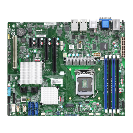
Page 16: Board Image
2.1 Board Image S5552 This picture is representative of the latest board revision available at the time of publishing. The board you receive may not look exactly like the above picture. http://www.tyan.com... -
Page 17: Block Diagram
2.2 Block Diagram S5552 Block Diagram http://www.tyan.com... -
Page 18: Motherboard Mechanical Drawing
2.3 Motherboard Mechanical Drawing http://www.tyan.com... -
Page 19: Board Parts, Jumpers And Connectors
The board you receive may not look exactly like the above diagram. The DIMM slot numbers shown above can be used as a reference when reviewing the DIMM population guidelines shown later in the manual. For the latest board revision, please visit our web site at http://www.tyan.com. http://www.tyan.com... - Page 20 27.SYS_ FAN3 (J40) 10. SYS_FAN4 (J35) 28.SATA 7 (J22) 11. SYS_FAN5 (J37) 29.SAS 0-3 (J79) 12. IPMB Header (J31) 13. TYAN Module Header (DBG_HD1) 30.SYS_FAN2 (J38) 14. SAS 4~7 (J78) 31.SYS_FAN1 (J36) 15. FPB USB2.0/ USB3.1x2 (J74) 32.CPU0_FAN (J34) 33. PSMI Header (J50) 16.
- Page 21 RST_SW# SMBus SDA SMBus SCL SYS_ID_SW# INTRUSION# TEMP SENSOR LAN2 ACTLED+ NMI_SW# LAN2 ACTLED- J31: IPMB Connector Signal Signal BMC_SMB_DATA BMC_SMB_CLK DBG_HD1: TYAN Module Header Signal Signal P3V3 FRAME_N LAD0 LAD1 PLT_RST_N LAD2 LAD3 CLK_33M DBG_SERIRQ DBG_PRES_N VCC3_AUX P3V3(NI) / GND RST_ESPI_RESET_N http://www.tyan.com...
- Page 22 J15, J17, J20, J21, J22, J23: SATA Connectors Name TYPE Connects to the Serial ATA ready drives via the Serial ATA cable. J16, J19: SATA/SATA DOM Connectors Name TYPE Connects to the Serial ATA ready drives via the Serial ATA cable. http://www.tyan.com...
- Page 23 TACH7 TACH3 TACH8 TACH4 TACH9 TACH5 TACH10 PWM2 PWM1 TACH11 TACH12 P3V3_AUX PWM3 J33: Intruder Header Signal FM_INTRUDER_HDR_PCH_N Normal (Default) 1-2: CHASSIS COVER IS CLOSED <DEFAULT> Empty: CHASSIS COVER IS REMOVED J67: PHY LED Header Signal Signal PHY_LED_ACT PHY_LED_ACT_N http://www.tyan.com...
- Page 24 Signal Signal RX0+ RX0- RX1+ RX1- RX2+ RX2- TX1+ TX1- RX3+ TX2+ RX3- TX2- TX0+ TX3+ TX0- TX3- J12: Clear CMOS Jumper Signal RTCRST# RST_RTCRST_CONN_N PD_RST_RTCRST_N Normal (Default) 1-2: NORMAL RTC RESET <DEFAULT> 2-3: CLEAR RTC REGISTERS Clear CMOS http://www.tyan.com...
- Page 25 J10: ME Firmware Update Jumper Signal TP_ME_RCVR_BOOT PM_ME_RCVR_R P0_ME_RCVR_N Normal (Default) 1-2: Normal <DEFAULT> 2-3: ME FORCE UPDATE ME Force Update http://www.tyan.com...
-
Page 26: Installing The Processor And Heatsink
2.5 Installing the Processor and Heatsink The types of processors supported by the S5552 are listed in the 1.2 Hardware Specifications section on page 4. Check our website at http://www.tyan.com ® the latest list of validated Intel processors for this specific motherboard. - Page 27 4. Install the processor and make sure the golden arrow is located in the right direction. 5. Close the CPU socket cover. 6. Close the socket lever. http://www.tyan.com...
- Page 28 Intel . Please refer to the Intel website: http://www.intel.com ® The following diagram illustrates how to install the heatsink on the Intel Socket LGA1151: Apply the thermal grease. Place the heat sink on top of the CPU. http://www.tyan.com...
- Page 29 Secure the heatsink screws. Connect the heatsink fan cable. http://www.tyan.com...
-
Page 30: Tips On Installing Motherboard In Chassis
Be especially careful to look for extra stand-offs. If there are any stand-offs present that are not aligned with a mounting hole on the motherboard, it will likely short components on the back of the motherboard when installed. This will cause malfunction and/or damage to your motherboard. http://www.tyan.com... - Page 31 Some chassis include plastic studs instead of metal. Although the plastic studs are usable, MiTAC recommends using metal studs with screws that will fasten the motherboard more securely in place. Below is a chart detailing what the most common motherboard studs look like and how they should be installed. http://www.tyan.com...
-
Page 32: Installing The Memory
2.7 Installing the Memory Before installing memory, ensure that the memory you have is compatible with the motherboard and processor. Check the TYAN Web site at http://www.tyan.com details of the type of memory recommended for your motherboard. http://www.tyan.com... - Page 33 - Use the same # of ranks per DIMM 4. Support DDR4 (ECC and Non-ECC) UDIMM. 5. The memory slots of DDR4 channels should be populated on a farthest first fashion. This means that blue connector cannot be populated if black is empty. http://www.tyan.com...
- Page 34 Supported UDIMM (Client OS) (Client OS) Intel’ C246 Supported Non-ECC Not Supported Not Supported (Workstation (Server OS) (Server OS) and Advanced Server, UDIMM ECC Supported Supported Supported non-mobile UDIMM Mix configurations) ECC with Not Supported Not Supported Supported Non-ECC http://www.tyan.com...
- Page 35 Memory Installation Procedure Follow these instructions to install memory modules into the S5552. Unlock a DIMM socket by Press the retaining clip outwardly in the following illustration. Align the memory module with the socket,such that the DIMM NOTCH match the KEY SLOT on the socket.
-
Page 36: Attaching Drive Cables
2.8 Attaching Drive Cables The following illustrates how to make a SATA/SAS Cable connection. If you are in need of SATA/SAS cables or power adapters please contact your local sales representative. Attaching SATA Cables Attaching SAS Cables http://www.tyan.com... -
Page 37: Installing Add-In Cards
Doing so allows air to circulate within the chassis more easily, thus improving cooling for all installed devices. NOTE: You must always unplug the power connector from the motherboard before performing system hardware changes to avoid damaging the board or expansion device. http://www.tyan.com... -
Page 38: Connecting External Devices
The implementation is convenient to onsite service technicians that need to press the power button when he/she is at the rear side of the system. Please visit https://www.tyan.com to download the latest BMC firmware release and flash it to your systems. - Page 39 1Gbps Ethernet port Link/Activity LED Scheme Left LED(LED2) Right LED(LED1) (Link/Activity) (Speed) No Link Link Green 10 Mbps Active Blinking Green Link Green Green 100 Mbps Active Blinking Green Green Link Amber Green 1000 Mbps (1Gbps) Active Amber Blinking Green http://www.tyan.com...
-
Page 40: Installing The Power Supply
2.11 Installing the Power Supply There are Two (2) power connectors on your S5552 motherboard. The S5552 supports ATX 12V power supply. PWR1: ATX 24-Pin Power Connector Pin-out Signal Signal +3.3V +3.3V +3.3V -12V PS_ON# PWR_OK 5VSB +12V +12V +3.3V... -
Page 41: Chapter 3: Bios Setup
Exit current menu <F1> General help <F2> Previous values <F3> Load the Optimal default configuration values of the menu <F4> Save and exit <K> Scroll help area upwards <M> Scroll help area downwards <PgUp> / <PgDn> Move cursor to next/previous page http://www.tyan.com... - Page 42 BIOS menus are continually changing due to continual BIOS updates over the product lifespan of the motherboard. The BIOS menus provided are current as of the date when this manual was written. Please visit TYAN’s website at http://www.tyan.com for information on BIOS updates available for this specific motherboard.
-
Page 43: Main Menu
Platform Information It displays Platform information. Memory Information This displays the total memory size. System Date Adjust the system date. MM (Months): DD (Days): YYYY (Years) System Time Adjust the system clock. HH (24 hours format): MM (Minutes): SS (Seconds) http://www.tyan.com... -
Page 44: Advanced Menu
This section facilitates configuring advanced BIOS options for your system. iSCSI Configuration Configure the iSCSI parameters Option ROM Dispatch Policy Option ROM Dispatch Policy Trusted Computing Trusted Computing settings. CPU Configuration CPU Configuration parameters Server ME Configuration Server ME Configuration ACPI Settings System ACPI Parameters. http://www.tyan.com... - Page 45 CSM Configuration, Enable/Disable Option ROM execution setting, etc USB Configuration USB Configuration Parameters. Onboard Device Configuration Onboard Device and Function Configuration. S5 RTC Wake Settings S5 RTC Wake Settings Super IO Configuration System Super IO Chip Parameters Hardware Health Configuration Hardware Health Configuration http://www.tyan.com...
- Page 46 Step 4. Save changes and reboot. Step 5. Enter to iSCSI Configuration Step 6. Set iSCSI Initator Name (Ex:iqn.dqa) Step 7. Enter to “Add an Attempt” Step 8. Enter to a Device (Ex MAC A0:42:3F:3A:F7:F0) Step 9. Set Configuration items: http://www.tyan.com...
- Page 47 3.3.1.1 Add an Attempt Read only. http://www.tyan.com...
- Page 48 The timeout value in milliseconds. The minimum value is 100 milliseconds and the maximum is 20 seconds. Configure ISID OUI-format ISID in 6 bytes, default value is derived from MAC address. Only last 3 bytes are configurable. Example: update 0ABBCCDDEEFF to OABBCCF07901 by input F07901. http://www.tyan.com...
- Page 49 Target Port Target Port. Boot LUN Hexadecimal representation of the LU number. Examples are: 4752-3A4F-6b7e-3F99, 6734-9-156f-127, 4186-9. Authentication Type Authentication method: CHAP, Kerberos, or None. CHAP / None Save Changes Must reboot system manually for changes to take place. http://www.tyan.com...
- Page 50 3.3.1.2 Delete Attempts Attempt 1 MAC: A0:42:3F:3A:F7:F0, PFA: Bus 1/ Dev 0 / Func 0, iSCSI mode: Disabled, IP version: IP4. Disabled / Enabled Commit Changes and Exit Commit Changes and Exit. Discard Changes and Exit Discard Changes and Exit. http://www.tyan.com...
- Page 51 Change the order of Attempts using +/- keys. Use arrow keys to select the attempt then press +/- to move the attempt up/down in the attempt order list. Attempt 1 / Attempt # Commit Changes and Exit Commit Changes and Exit. Discard Changes and Exit Discard Changes and Exit. http://www.tyan.com...
- Page 52 Enable or Disable Option ROM execution for selected Slot. Disabled / Enabled PCIE #3 NOT FOUND Enable or Disable Option ROM execution for selected Slot. Disabled / Enabled PCIE #4 NOT FOUND Enable or Disable Option ROM execution for selected Slot. Disabled / Enabled http://www.tyan.com...
- Page 53 Enables or Disables BIOS support for security device. O.S will not show Security Device. TCG EFI protocol and IN71A interface will not be available. SHA-1 PCR Bank Enable or Disable SHA-1 PCR Bank Disabled Enabled SHA256 PCR Bank Enable or Disable SHA-256 PCR Bank Disabled Enabled http://www.tyan.com...
- Page 54 TPM 1.2 will restrict support to TPM 1.2 devices, TPM 2.0 will restrict support to TPM 2.0 devices, Auto will support both with the default set to TPM 2.0 devices if not found, TPM 1.2 devices will be enumerated. TPM 1.2 TPM 2.0 / Auto http://www.tyan.com...
- Page 55 3.3.4 CPU Configuration http://www.tyan.com...
- Page 56 SGX Launch Control Policy Software Guard Extensions (SGX) Launch Control Policy, Options are: Intel Locked – Select Intel’s Launch Enclave. Unlocked – Enable OS/VMM configuration of Launch Enclave. Locked – Allow owner to configure Launch Enclave. Unlocked / Intel Locked / Locked http://www.tyan.com...
- Page 57 Enable/Disable processor Turbo Mode (requires Intel Speed Step or Intel Speed shift to be available and enabled). Disabled / Enabled Intel(R) Speed Shift Technology Enable/ Disable Intel(R) Speed Shift Technology support. Enabling will expose the OPPC v2 interface to allow for hardware controlled P- states. Disabled / Enabled http://www.tyan.com...
- Page 58 Package C State Limit Maximum Package C State Limit Setting. Cpu Default: Leaves to Factory default value. Auto: Initializes to deepest available Package C State Limit. Auto / Cpu Default / C8 / C7 / C6 / C3 / C2 / C0/C1 http://www.tyan.com...
- Page 59 3.3.5 Server ME Configuration Read Only http://www.tyan.com...
- Page 60 Enables or Disables System ability to Hibernate (OS/SA Sleep State). This option may not be effective with some operating systems. Disabled / Enabled ACPI Sleep State Select the highest ACPI sleep state the system will enter when the SUSPEND button is pressed. Suspend Disabled / S3 (Suspend to RAM) http://www.tyan.com...
- Page 61 Serial Port for Out-Of-Band Management/Windows Emergency Services (EMS) Console Redirection Console redirection enable or disable. Disabled / Enabled Console Redirection Settings The settings specify how the host computer (which the user is using) will exchange data. Both computers should have the same or compatible settings. http://www.tyan.com...
- Page 62 1’s in the data bits is odd. Mark: parity bit is always 1. Space: parity bit is always 0. Mark and Space parity do not allow for error detection. None / Even / Odd / Mark / Space http://www.tyan.com...
- Page 63 With this mode enabled only text will be sent. This is to capture Terminal data. Disabled / Enabled Resolution 100x31 Enable or disable extended terminal resolution. Disabled / Enabled Putty KeyPad Select Function Key and KeyPad on Putty. VT100 / LINUX / XTERMR6 / SCO / ESCN / VT400 http://www.tyan.com...
- Page 64 When Bootloader is selected then Legacy Console Redirection is disabled before booting to legacy OS. When Always Enable is selected, then Legacy Console Redirection is enabled for legacy OS. Default setting for this option is set to Always Enable. Always Enable / Bootloader http://www.tyan.com...
- Page 65 Help with Terminal Type/Emulation. VT100 / VT100+ / VT-UTF8 / ANSI Bits per Second Select serial port transmission speed. The speed must be matched on the other side. Long or noisy lines may require lower speeds. 9600 / 19200 / 57600/ 115200 http://www.tyan.com...
- Page 66 ‘start’ signal can be sent to restart the flow. Hardware flow control uses two wires to send start/stop signal. None / Hardware RTS/CTS / Software Xon/Xoff Data Bits / Parity / Stop Bits Read only. http://www.tyan.com...
- Page 67 Enables or Disables 64bit capable Devices to be decoded in Above 4G Address Space. Enabled / Disabled SR-IOV Support If system has SR-IOV capable PCIe devices, this option Enables or Disables Single root IO virtualization Support Enabled / Disabled http://www.tyan.com...
- Page 68 3.3.9 Network Stack Configuration Network Stack Enable/Disable UEFI Network Stack Disabled / Enabled http://www.tyan.com...
- Page 69 Controls the execution of UEFI and legacy PXE OpROM UEFI / legacy Video Controls the execution of UEFI and legacy PXE OpROM UEFI / legacy Other PCI devices Determines OpRom execution policy for devices other than Network, Storage, or Video UEFI / legacy http://www.tyan.com...
- Page 70 USB Mass Storage Driver Support Enable/Disable USB Mass Storage Driver Support. Enabled Disabled Port 60/64 Emulation Enable I/O port 60h/64h emulation support. This should be enabled for the complete USB keyboard legacy support for non- USB aware OSes. Enabled Disabled http://www.tyan.com...
- Page 71 Controller. ‘AUTO’ uses default value: for a Root port it is 100 ms, for a Hub port the delay is taken from Hub descriptor. Auto / Manual 3.3.12 Onboard Device Configuration Onboard VGA Enable or disable onboard VGA. Disabled / Enabled http://www.tyan.com...
- Page 72 Wake system from S5 Enable or disable system wake on alarm event. Select Fixed time, system will wake on the hr::min::sec specified. Select dynamic time, system will wake on the current time+ increase minute(s) Disabled / Fixed time / Dynamic time http://www.tyan.com...
- Page 73 3.3.14 Super IO Configuration Serial Port 1 Configuration Set Parameters of Serial Port 1 (COMA) Serial Port 2 Configuration Set Parameters of Serial Port 2 (COMB) http://www.tyan.com...
- Page 74 / IO=3F8h, IRQ=3, 4, 5, 6, 7, 9, 10, 11, 12; / IO=2F8h; IRQ=3, 4, 5, 6, 7, 9, 10, 11, 12; / IO=3E8h, IRQ=3, 4, 5, 6, 7, 9, 10, 11, 12; / IO=2E8h, IRQ=3, 4, 5, 6, 7, 9, 10, 11, 12; http://www.tyan.com...
- Page 75 / IO=3F8h, IRQ=3, 4, 5, 6, 7, 9, 10, 11, 12; / IO=2F8h; IRQ=3, 4, 5, 6, 7, 9, 10, 11, 12; / IO=3E8h, IRQ=3, 4, 5, 6, 7, 9, 10, 11, 12; / IO=2E8h, IRQ=3, 4, 5, 6, 7, 9, 10, 11, 12; http://www.tyan.com...
- Page 76 3.3.15 Hardware Health Configuration Fan speed Control Fan speed control Manual / Full Speed PWM Minimal Duty Cycle (%) Duty Cycle control range 30 BMC Alert Beep Enable/Disable BMC Alert Beep Off / On PMBus Support PMBus Support Disabled Enabled http://www.tyan.com...
- Page 77 3.3.15.1 Sensor Data Register Monitoring When you enter the Sensor Data Register Monitoring submenu, you will see the following dialog window pop out. Please wait 8~10 seconds. NOTE 1: SDR cannot be modified. Read only. http://www.tyan.com...
- Page 78 http://www.tyan.com...
-
Page 79: Chipset Menu
3.4 Chipset Menu North Bridge System Agent (SA) Parameters. South Bridge PCH Parameters http://www.tyan.com... - Page 80 3.4.1 North Bridge Configuration Memory Configuration Memory Configuration Parameters Graphics Configuration Graphics Configuration DMI/DPI Configuration Control various DMI functions PEG Port Configuration PEG Port Options VT-d VT-d capability Disabled / Enabled http://www.tyan.com...
- Page 81 3.4.1.1 Memory Configuration Maximum Memory Frequency Maximum Memory Frequency Selections in Mhz. Valid values should match the refclk, i.e. divide by 133 or 100 Auto / 2133 / 2400 / 2666 ECC Support Enable/ disable DDR Ecc Support Disabled Enabled http://www.tyan.com...
- Page 82 3.4.1.2 Graphics Configuration Primary Display Select which of IGFX/PEG/ PCI Graphics device should be Primary Display or select SG for Switchable Gfx. Auto / PEG / PCH PCIe http://www.tyan.com...
- Page 83 DMI Max Link Speed Set DMI Speed Gen1/Gen2/ Gen3 Auto / Gen1 / Gen2 / Gen3 DMI Link ASPM Control Enable/Disable the control of Active State Power Management on SA side of the DMI Link. Disabled L0s / L1 / L0sL1 http://www.tyan.com...
- Page 84 Force X1/ Force X2 / Force X4 / Force X8 ASPM Control ASPM support for the PEG 1.This has to effect if PEG is not the currently active device. Disabled / Auto / ASPM L0s / ASPM L1 / ASPM L0sL1 http://www.tyan.com...
- Page 85 Select PEG0 Max Payload Size; Choose Auto/Default Device Capability) or force to 128/256 Bytes Auto / 128 / 256 TLP PEG1 Max Payload size Select PEG1 Max Payload Size; Choose Auto/Default Device Capability or force to 128 /256 Bytes Auto / 128 / 256 TLP http://www.tyan.com...
- Page 86 PCI Express Configuration settings DeepSx Power Policies Configure the DeepSx Mode configuration Disabled / Enabled in S4-S5 Restore AC Power Loss Select AC power state when power is re-applied after a power failure. Power On Power Off Last State http://www.tyan.com...
- Page 87 SATA Device Type Identify the SATA port is connected to Solid State Drive or Hard Disk Drive Hard Disk Drive Solid State Drive Serial ATA Port 1 / SATADOM2 Hot plug Designated this port as Hot pluggable Disabled Enabled http://www.tyan.com...
- Page 88 Solid State Drive 3.4.2.2 PCI Express Configuration DMI Link ASPM Control The control of Active State Power Management of the DMI Link. Disabled L0s / L1 / L0sL1 / Auto PCI Express Root Port 1/7/9/10/11/12/21/22/23/24 PCI Express Root Port Settings http://www.tyan.com...
- Page 89 Set the ASPM Level: Force L0s – Force all links to L0s State AUTO – BIOS auto configure DISABLE – Disables ASPM Disabled Enabled L1 Substates PCI Express L1 Substates settings Disabled L1.1 / L1.1 & L1.2 PCIe Speed Configure PCIe Speed Auto Gen1 / Gen2 / Gen3 http://www.tyan.com...
-
Page 90: Server Management
3 minutes / 4 minutes / 5 minutes / 6 minutes FRB-2 Timer Policy Configure how the system should respond if the FRB-2 Timer expires. Not available if FRB-2 Timer is disabled. Do Nothing / Reset / Power Down / Power Cycle http://www.tyan.com... - Page 91 Not available if OS Boot watchdog Timer is disabled. Do Nothing / Reset / Power Down / Power Cycle BMC Logo Enable or Disable BMC Logo Disabled / Enabled System Event Log Press<Enter> to change the SEL event log configuration. BMC network Configuration Configure BMC network parameters http://www.tyan.com...
- Page 92 Choose options for reactions to a full SEL. Do Nothing / Erase Immediately Log EFI Status Codes Disable the logging of EFI Status Codes or log only error code or only progress code or both. Disabled / Both / Error Code / Progress Code http://www.tyan.com...
- Page 93 3.5.2 BMC Event Log http://www.tyan.com...
-
Page 94: Security
BMC). Unspecified option will not modify any BMC network parameters during BIOS phase. Unspecified / Static / DynamicBmcDhcp / DynamicBmcNonDhcp Management Port 1/2 IPV6 Support Enable or Disable LAN1 IPV6 Support Disabled / Enabled 3.6 Security Administrator Password Set Administrator Password. User Password Set User Password. http://www.tyan.com... - Page 95 (PK) is enrolled and the System is in User mode. The mode change requires platform reset Disabled / Enabled Secure Boot Mode Secure Boot mode selector. ’Custom’ mode enables users to change Image execution policy and manage secure boot keys. Standard / Custom http://www.tyan.com...
- Page 96 3.6.1.1 Restore Factory Keys Submenu Restore Factory Keys Force System to User Mode. Install factory default Secure Boot Key databases. When Press ‘Yes’ to proceed When Press ‘No’ to cancel http://www.tyan.com...
- Page 97 Reset To Setup Mode Delete all Secure Boot key databases from NVRAM Deleting all variables will reset the System to setup Mode When Press ‘Yes’ to proceed When Press ‘No’ to cancel Key Management Enables experienced users to modify Secure Boot variables http://www.tyan.com...
- Page 98 Copy NVRAM content of Secure Boot variables to files in a root folder on a file system device Enroll Efi Image Allow the image to run in Secure Boot mode. Enroll SHA256 Hash certificate of a PE image into Authorized Signature Database(db) http://www.tyan.com...
- Page 99 EFI_CERT_X509 (DER encoded) c) EFI_CERT_RSA2048 (bin) d) EFI_CERT_SHA256,384,512 2. Authenticated UEFI Variable 3. EFI PE/COFF Image(SHA256) Key Source: Default, External, Mixed, Test Forbidden Signatures Enroll Factory Defaults or load certificates from a file: 1. Public Key Certificate in: http://www.tyan.com...
- Page 100 Enroll Factory Defaults or load certificates from a file: 1. Public Key Certificate in: a) EFI_SIGNATURE_LIST b) EFI_CERT_X509 (DER encoded) c) EFI_CERT_RSA2048 (bin) d) EFI_CERT_SHA256,384,512 2. Authenticated UEFI Variable 3. EFI PE/COFF Image(SHA256) Key Source: Default, External, Mixed, Test http://www.tyan.com...
-
Page 101: Boot
Enable or disable Quiet Boot option. Disabled / Enabled Boot Option #1#2#3#4#5 Sets the system boot order Device Name / Disabled Endless boot Restart the INT19 boot process automatically if all IPL devices fail to boot. Disabled / Enabled http://www.tyan.com... - Page 102 USB Device BBS Priorities Set the order of the legacy devices in this group Add New Boot Option Add a new EFI boot option to the boot order Delete Boot Option Remove an EFI boot option from the boot order http://www.tyan.com...
- Page 103 3.7.1 Hard Drive BBS Priorities Configuration Boot Option #1 Sets the system boot order Device Name / Disabled http://www.tyan.com...
- Page 104 3.7.2 USB Device BBS Priorities Configuration Boot Option #1 Sets the system boot order Device Name / Device Name / Disabled Boot Option #2 Sets the system boot order Device Name / Device Name / Disabled http://www.tyan.com...
- Page 105 3.7.3 Add New Boot Option Configuration Add boot option Specify name for new boot option Path for boot option Enter the path to the boot option in the format fsk:\ path\ filename.efi Create Creates the newly formed boot option http://www.tyan.com...
- Page 106 3.7.4 Delete Boot Configuration Delete Boot Option Remove an EFI boot option from the boot order. Select one to Delete / Device Name http://www.tyan.com...
-
Page 107: Save & Exit
Reset system setup without saving any changes. Save Changes Save changes done so far to any of the setup options. Discard Changes Discard changes done so far to any of the setup options. Restore Defaults Restore/Load Default values for all the setup options. http://www.tyan.com... - Page 108 Save as User Defaults Save the changes done so far as User Defaults. Restore User Defaults Restore the User Defaults to all the setup options. Boot Override Device Name http://www.tyan.com...
-
Page 109: Chapter 4: Diagnostics
BIOS flash failure, you must contact your dealer for a replacement BIOS. There are no exceptions. TYAN does not have a policy for replacing BIOS chips directly with end users. In no event will TYAN be held responsible for damages done by the end user. -
Page 110: Amibios Post Code (Aptio)
South Bridge initialization before microcode loading 0x05 OEM initialization before microcode loading 0x06 Microcode loading 0x07 AP initialization after microcode loading 0x08 North Bridge initialization after microcode loading 0x09 South Bridge initialization after microcode loading 0x0A OEM initialization after microcode loading 0x0B Cache initialization http://www.tyan.com... - Page 111 Memory initialization. Configuring memory 0x2F Memory initialization (other) 0x30 Reserved for ASL (see ASL Status Codes section below) 0x31 Memory Installed 0x32 CPU post-memory initialization is started. 0x33 CPU post-memory initialization. Cache initialization CPU post-memory initialization. Application Processor(s) (AP) 0x34 initialization http://www.tyan.com...
- Page 112 S3 Resume Progress Codes 0xE0 S3 Resume is started (S3 Resume PPI is called by the DXE IPL). 0xE1 S3 Boot Script execution 0xE2 Video repost 0xE3 OS S3 wake vector call 0xE4 – 0xE7 Reserved for future AMI progress codes http://www.tyan.com...
- Page 113 DXEIPL was not found. DXE Core Firmware Volume was not found. Recovery failed S3 Resume failed Reset PPI is not available. DXE Phase Status Code Description 0x60 DXE Core is started. 0x61 NVRAM initialization 0x62 Installation of the South Bridge Runtime Services http://www.tyan.com...
- Page 114 PCI Bus Hot Plug Controller initialization 0x94 PCI Bus Enumeration 0x95 PCI BUS Request Resources 0x96 PCI Bus Assign Resources 0x97 Console output devices connect 0x98 Console Input devices connect 0x99 Super IO initialization 0x9A USB initialization is started. http://www.tyan.com...
- Page 115 0xC0 – 0xCF OEM BDS initialization codes DXE Error Codes 0xD0 CPU initialization error 0xD1 North Bridge initialization error 0xD2 South Bridge initialization error 0xD3 Some of the Architectural Protocols are not available 0xD4 PCI resource allocation error. Out of Resources http://www.tyan.com...
- Page 116 System is waking up from the S3 sleep state. 0x40 System is waking up from the S4 sleep state. System has transitioned into ACPI mode. Interrupt controller is in 0xAC APIC mode. System has transitioned into ACPI mode. Interrupt controller is in 0xAA APIC mode. http://www.tyan.com...
-
Page 117: Appendix I: Fan And Temp Sensors
(rpm) Temp Sensor: SAS_Area_Temp,M/B_Air_Inlet and SAS_Air_Outlet. They detect the system temperature around. NOTE: The system temperature is measured in a scale defined by Intel, not in Fahrenheit or Celsius. http://www.tyan.com... - Page 118 BIOS Temp Sensor Name Explanation: http://www.tyan.com...
- Page 119 Fan speed of SYS_FAN_5 SYS_FAN_5 Fan speed of SYS_FAN_6 SYS_FAN_6 Fan speed of SYS_FAN_7 SYS_FAN_7 Fan speed of SYS_FAN_8 SYS_FAN_8 Fan speed of SYS_FAN_9 SYS_FAN_9 Fan speed of SYS_FAN_10 SYS_FAN_10 Fan speed of SYS_FAN_11 SYS_FAN_11 Fan speed of SYS_FAN_12 SYS_FAN_12 http://www.tyan.com...
- Page 120 NOTE http://www.tyan.com...
-
Page 121: Glossary
(reading to or writing from a disk drive a single time is much faster than doing so repeatedly) there is the possibility of losing your data should the system crash. Information in a buffer is temporarily stored, not permanently saved. http://www.tyan.com... - Page 122 (like soundcards or keyboards) to access the main memory without involving the CPU. This frees up CPU resources for other tasks. As with IRQs, it is vital that you do not double up devices on a single line. Plug-n-Play devices will take care of this for you. http://www.tyan.com...
- Page 123 ROM chip which can, unlike normal ROM, be updated. This allows you to keep ® ’s up with changes in the BIOS programs without having to buy a new chip. TYAN BIOS updates can be found at http://www.tyan.com ESCD (Extended System Configuration Data): a format for storing information about Plug-n-Play devices in the system BIOS.
- Page 124 PXE (Preboot Execution Environment): one of four components that together make up the Wired for Management 2.0 baseline specification. PXE was designed to define a standard set of preboot protocol services within a client with the goal of allowing networked-based booting to boot using industry standard protocols. http://www.tyan.com...
- Page 125 NVIDIA s (graphics communications processing units) and NVIDIA MCPs (media and processors). application Depending on the , NVIDIA SLI can deliver as much as two times the performance of a single GPU configuration. http://www.tyan.com...
- Page 126 CPUs without damaging the sensitive CPU pins. The CPU is lightly placed in an open ZIF socket, and a lever is pulled down. This shifts the processor over and down, guiding it into the board and locking it into place. http://www.tyan.com...
-
Page 127: Technical Support
"TYAN's tech support is some of the most impressive we've seen, with great response time and exceptional organization in general" - Anandtech.com Help Resources: 1. See the beep codes section of this manual. - Page 128 (RMA) number. The RMA number Should be prominently displayed on the outside of the shipping carton and the package should be mailed prepaid. ® TYAN will pay to have the board shipped back to you. Notice for the USA Compliance Information Statement (Declaration of...
Need help?
Do you have a question about the S5552 and is the answer not in the manual?
Questions and answers