Table of Contents
Advertisement
Copyright
Copyright © MiTAC Computer Corporation, 2012. All rights reserved. No part of
this manual may be reproduced or translated without prior written consent from
MiTAC Computer Corp.
Trademark
All registered and unregistered trademarks and company names contained in
this manual are property of their respective owners including, but not limited to
the following.
®
TYAN
is a trademark of MiTAC Computer Corporation
®
Intel
is a trademark of Intel
®
®
AMI
, AMIBIOS
®
Microsoft
, Windows
®
Aspeed
is a trademark of Aspeed Technology Inc.
Notice
Information contained in this document is furnished by MiTAC Computer
Corporation and has been reviewed for accuracy and reliability prior to printing.
MiTAC assumes no liability whatsoever, and disclaims any express or implied
warranty, relating to sale and/or use of TYAN
warranties relating to fitness for a particular purpose or merchantability. MiTAC
retains the right to make changes to product descriptions and/or specifications
at any time, without notice. In no event will MiTAC be held liable for any direct
or indirect, incidental or consequential damage, loss of use, loss of data or other
malady resulting from errors or inaccuracies of information contained in this
document.
S5510
Version 1.2
®
Corporation.
and combinations thereof are trademarks of AMI Technologies.
®
are trademarks of Microsoft Corporation.
®
products including liability or
Advertisement
Table of Contents

Related Manuals for TYAN S5510


Summary of Contents for TYAN S5510
- Page 1 Corporation and has been reviewed for accuracy and reliability prior to printing. MiTAC assumes no liability whatsoever, and disclaims any express or implied ® warranty, relating to sale and/or use of TYAN products including liability or warranties relating to fitness for a particular purpose or merchantability. MiTAC retains the right to make changes to product descriptions and/or specifications at any time, without notice.
-
Page 2: About This Guide
Appendix: Fan and Temp Sensors This section aims to help readers identify the locations of some specific Fan and Temp Sensors on the motherboard. A table of BIOS Temp sensor name explanation is also included for readers’ reference. http://www.TYAN.com... -
Page 3: Table Of Contents
3.10.1 - System Event Log Sub-Menu ..............87 3.10.2 - BMC Network Configuration Sub-Menu..........88 3.11 - Event Logs .....................89 3.12 - Save & Exit Menu ...................90 Chapter 4: Diagnostics ..............92 4.1 - Beep Codes....................92 4.2 - Flash Utility....................92 Glossary..................101 Technical Support .................109 http://www.TYAN.com... -
Page 4: Before You Begin
1x USB 2.0 422736300007 ASSY;SBU,USB CONN,2 Cable PORT,S2865 TF-I/O 341T44000001 SHIELDING;SBU,SUS,500 1x I/O shield 12-6AP,S5512 1x S5510 User’s manual 1x S5510 Quick reference guide TFSOFTWARE;SBU,TYAN ® 1x TYAN Driver Driver CD FOR INTEL C200 Series If any of these items are missing, please contact your vendor/dealer for replacement before continuing with the installation process. -
Page 5: Congratulations
(32nm / 22nm) series, socket H2 LGA1155 processor. The S5510 has four 240-pin DIMM slots that can support up to 32GB of unbuffered ECC DDRIII. The memory interface supports speed up to 1333/1066 MHz. There are also 2 memory channels, DIMM can be installed in either a single or a dual channel (interleaved) configuration, which requires modules of the same size and speed to be installed in pairs. - Page 6 Class A FCC (DoC) Regulation CE (DoC) 10° C ~ 35° C (50° F~ 95° F) Operating Temp. Operating Non-operating - 40° C ~ 70° C (-40° F ~ 158° F) Environment Temp. 90%, non-condensing at 35° C In/Non-operating http://www.TYAN.com...
- Page 7 Humidity RoHS 6/6 Compliant Yes RoHS (1) S5510 Motherboard Motherboard (1) User's manual / (1) Quick Ref. Guide Manual Package (1) TYAN installation CD Installation CD Contains (1) I/O Shield I/O Shield (6) SATA signal cables Cable SATA TYAN S5510-LE (S5510G2NR-LE)
- Page 8 (1) TYAN installation CD Installation CD Contains (1) I/O Shield I/O Shield (6) SATA signal cables Cable SATA TYAN S5510 (S5510G2NR-HE [BTO]) Intel Xeon Processor E3-1200 series, Intel Core i3- Supported CPU 2100 series Series LGA 1155/ (1) Socket Type / Qty...
- Page 9 / User-configurable H/W monitoring / Auto-configurable of hard disk types Micro ATX Form Factor Physical Dimension 9.6"x9.6" (243.8x243.8mm) Board Dimension Operating Please visit our web site for the latest update. OS supported list System Class A FCC (DoC) Regulation CE (DoC) http://www.TYAN.com...
- Page 10 - 40° C ~ 70° C (-40° F ~ 158° F) Operating Temp. Environment In/Non-operating 90%, non-condensing at 35° C Humidity RoHS 6/6 Complaint Yes RoHS (1) S5510 Motherboard Motherboard (1) User's manual / (1) Quick Ref. Guide Manual (1) TYAN installation CD Installation CD Package Contains (1) I/O Shield...
-
Page 11: Software Specifications
TYAN ’s products with FAQs, online manuals and BIOS upgrades and more. 1.3 - Software Specifications ® For OS (operation system) support, please check the TYAN website for the latest information. 1.4 - AST2150 User Guide ®... -
Page 12: Chapter 2: Board Installation
Unplug the power from your computer power supply and then touch a safely grounded object to release static charge (i.e. power ® supply case). For the safest conditions, TYAN recommends wearing a static safety wrist strap. (2) Hold the motherboard by its edges and do not touch the bottom of the board, or flex the board in any way. -
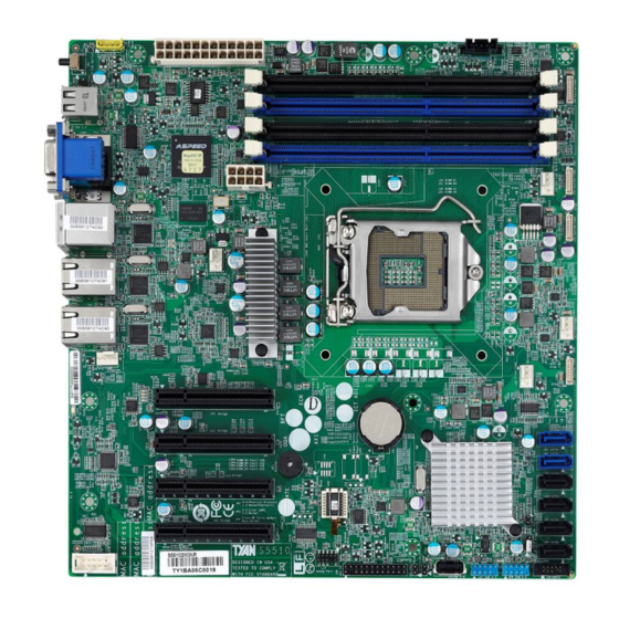
Page 13: Board Image
2.1 - Board Image S5510GM3NR http://www.TYAN.com... - Page 14 S5510G2NR-LE This diagram is representative of the latest motherboard revision available at the time of publishing. The board you receive may not look exactly like the above diagram. http://www.TYAN.com...
-
Page 15: Block Diagram
2.2 - Block Diagram S5510GM3NR Block Diagram http://www.TYAN.com... - Page 16 S5510G2NR [BTO] Block Diagram http://www.TYAN.com...
- Page 17 S5510G2NR-LE Block Diagram http://www.TYAN.com...
- Page 18 S5510G2NR-HE [BTO] Block Diagram http://www.TYAN.com...
-
Page 19: Board Parts, Jumpers And Connectors
• The grey area represents varying parts in the 4 SKUs which will be removed or remained. • PCIE Slot 5 is not present in G2NR-LE version. • Any other connectors or jumpers differences in the 4 SKUs please refer to S5510 SKU Comparison Table II http://www.TYAN.com... - Page 20 Jumpers & Connectors S5510 SKU Comparison Table II S5510 series jumper and connector Support SKUs G2NR- G2NR- Jumper/Connector Function G3NR G2NR 4-Pin Fan Connectors J9/J10/J33/J35/J43 Fan2&Fan5/Fan3&Fan6/ Fan1/Fan 4 J42/J44/J45/J46 8-Pin Fan Connectors ID LED Switch Button Front Panel IDLED Switch 2 Pin Header...
- Page 21 Jumper Placement http://www.TYAN.com...
- Page 22 J42/J44/J45/J46: 8-Pin FAN Connector (Only support on S5510GM3NR) Signal PWM1 VCC1 Tachometer1 GND1 GND2 Tachometer2 VCC2 PWM2 NOTE: Do not mix 8-pin Fan headers with 4-pin Fan headers. Mixing these fan headers will cause problems to the system. These connectors are only for the barebone. http://www.TYAN.com...
- Page 23 ID_LED J23/J24 http://www.TYAN.com...
- Page 24 ID_LED+ PWRLED-(GND) ID_LED-(GND) HD_LED+ Fault LED1- HD_LED- Fault LED2- Power Switch+ LAN1_ACTIVE_LED+ LAN1_ACTIVE_LED- Reset Switch+ SMB_DATA SMB_CLK ID Switch+ INTRUSION# TEMP Sensor LAN2_ACTIVE_LED+ NMI Switch# LAN2_ACTIVE_LED- J23: LAN3 Active LED Header (only support on S5510GM3NR) Signal LAN3_ACTIVE_LED + LAN3_ACTIVE_LED-(GND) http://www.TYAN.com...
- Page 25 Signal V3AUX State Color Description Blue System identified System not identified The ID LED can be activated remotely using IPMI. NOTE: Please visit the TYAN Web Site at to download the http://www.tyan.com latest IPMI Configuration Guide for more details. http://www.TYAN.com...
- Page 26 J27/J28/J34 http://www.TYAN.com...
- Page 27 J28:Dual USB2.0 Header (Port2/Port3) Signal Signal USB 5V Power USB 5V Power USB Data- USB Data- USB Data+ USB Data+ J34: SGPIO Header Signal Signal SMB SCL SGPIO Data1 SMB SDA SGPIO Data0 SGPIO LOAD SGPIO Clock 3.3V standby BP HDD FAULT http://www.TYAN.com...
- Page 28 http://www.TYAN.com...
- Page 29 After flashing new BIOS please follow the following steps: Clear CMOS a. Clear CMOS b. Enter into BIOS setup menu and load Default Settings, Then do a Save and Exit from setup. JP4:ME recovery function set Open: OPEN (Default) Closed: CLOSE(ME force update) http://www.TYAN.com...
-
Page 30: Installing The Processor
2.4 - Installing the Processor ® Your brand new S5510, Intel “Sandy Bridge E3 series” processors are certified and supported with this motherboard. Check our website for latest processor support. http://www.tyan.com ® NOTE: TYAN is not liable for damage as a result of operating an unsupported configuration. - Page 31 CPU notches. Alignment key The CPU fits in only one correct orientation. Do not force the CPU into the socket to prevent bending the connectors on the socket and damaging the CPU. http://www.TYAN.com...
- Page 32 7. Insert the load lever under the retention tab. Retention knob For the safest method of installation and information on choosing ® the appropriate heat sink, using heat sinks validated by Intel ® Please refer to Intel s website at www.Intel.com http://www.TYAN.com...
-
Page 33: Installing The Heatsink
. Please refer to Intel’ s website at www.Intel.com. The following diagram illustrates how to install heat sink onto the CPU of S5510. 1. If a protective film covers the thermal interface material (TIM) on the underside of the heatsink, remove the protective film. -
Page 34: Thermal Interface Material
CPU lid (applying too much will actually reduce the cooling). Always check with the manufacturer of the heat sink & processor to ensure the thermal Interface material is compatible with the processor and meets the manufacturer’s warranty requirements. http://www.TYAN.com... -
Page 35: Tips On Installing Motherboard In Chassis
Place 8 screws into the holes indicated by circles to secure the mother board to the chassis. DO NOT overtighten the screws! Doing so can damage the Caution : motherboard. http://www.TYAN.com... - Page 36 Some chassis’ include plastic studs instead of metal. Although the plastic ® studs are usable, TYAN recommends using metal studs with screws that will fasten the motherboard more securely in place. Below is a chart detailing what the most common motherboard studs look like and how they should be installed.
-
Page 37: Installing The Memory
The figure illustrated the location of the DDR3 DIMM socket. ® TYAN S5510 series support up to 32GB of unbuffered (UDIMM) DDR3 with ECC1333/1066 MHz in 4 memory slots. All installed memory will automatically be detected and no jumpers or settings need changing. - Page 38 Recommended Memory Population Table ® To achieve the best performance, TYAN strongly recommended memory installation configuration as listed below: Table-1: Recommended memory population guide for Optimal performance of S5510...
-
Page 39: Memory Installation Procedure
Memory Installation Procedure Follow these instructions to install memory modules into the S5510. Ensure to unplug the power supply before adding or removing DIMMs or NOTE: other system components, Failure to do so may cause severe damage to both the motherboard and the components. -
Page 40: Attaching Drive Cables
2.9 - Attaching Drive Cables Attaching Serial ATA Cables S5510 is equipped with Serial ATA (SATA) channels. Connections for the drives are very simple. There is no need to set Master/Slave jumpers on SATA drives. If you are in need of SATA/SAS cables or power adapters please contact your place of purchase. -
Page 41: Installing Add-In Cards
Doing so allows air to circulate within the chassis more easily, thus improving cooling for all installed devices. YOU MUST ALWAYS unplug the power connector to the motherboard before performing system hardware changes to avoid damaging the board or expansion device. http://www.TYAN.com... -
Page 42: Connecting External Devices
COM1 port S5510GM3NR VGA port LAN 1 COM1 port LAN 2 USB Port*2 USB Port*2 (S5510G2NR / S5510G2NR-LE/ S5510G2NR-HE) Peripheral devices can be plugged straight into any of these ports but software may be required to complete the installation. http://www.TYAN.com... - Page 43 The chart below illustrates the different LED states. 10/100/1000 Mbps LAN Link/Activity LED Scheme Left LED Right LED Green Link 10 Mbps Blinking Green Active Green Green Link 100 Mbps Blinking Green Green Active Green Amber Link 1000 Mbps Blinking Green Amber Active No Link/10Mb mode(Right) http://www.TYAN.com...
-
Page 44: Installing The Power Supply
2.12- Installing the Power Supply There are power connectors on your S5510. It is required that you have an EPS12V power supply which has one 24-pin and one 8-pin connectors. 24-Pin 12V main PWR Connector (Input) Signal Signal +3.3V +3.3V +3.3V... -
Page 45: Finishing Up
In the rare circumstance that you have experienced difficulty, you can find help by asking your vendor for assistance. If they are not available for assistance, please find setup information and documentation online at our website or by calling your vendor’s support line. http://www.TYAN.com... -
Page 46: Chapter 3: Bios Setup
Load Fail Safe default configuration values of the menu <F3> Load the Optimal default configuration values of the menu <F4> Save and exit <Enter> Execute command or select submenu <Del>、<F2> Into BIOS setup menu <F11> BBS POPUP <F12> Boot from the network http://www.TYAN.com... -
Page 47: Getting Help
In particular, do not change settings in the Chipset section unless you are absolutely sure of what you are doing. The ® Chipset defaults have been carefully chosen either by TYAN or your system manufacturer for best performance and reliability. Even a seemingly small change to the Chipset setup options may cause the system to become unstable or unusable. -
Page 48: Bios Main Menu
Allow user to set system time and date. The Time is displayed in 24 hours format. The Date can be set from January 1st, 2005 to December 31, 2099 The values set in these two fields take effect immediately. http://www.TYAN.com... - Page 49 The right frame displays the key legend. Above the key legend is an area reserved for a text message. When an option is selected in the left frame, it is highlighted in white. Often, a text message will accompany it. http://www.TYAN.com...
-
Page 50: Bios Advanced Menu
Selection for Advanced ACPI Configuration. S5 RTC Wake Settings Configure S5 RTC Wake CPU Configuration Configure CPU SATA Configuration This menu helps you to set up or change the SATA Configuration. Onboard Device Configuration Configure Onboard Devices Info Report Configuration Info report configure http://www.TYAN.com... - Page 51 Hardware Health Configuration IPMI configuration including server monitoring and event log Super IO Configuration Configures Super IO Power Management Configuration Configure the Power Management Serial Port Console Redirection Redirect Serial Port Console CPU PPW Configuration Configure the CPU PPW http://www.TYAN.com...
- Page 52 [Suspend Disabled] / [S1 only (CPU Stop Clock)] / [S3 only (Suspend to RAM)] / [Both S1 and S3 available for OS to choose from] Default is [Both S1 and S3 available for OS to choose from] Lock Legacy Resources Enables or Disables Lock of Legacy Resources. [Enabled] / [Disabled] Default is [Disabled] http://www.TYAN.com...
- Page 53 [Enabled] / [Disabled] Default is [Disabled] Wake system with Dynamic Time Enable or Disable system wake on alarm event. When enabled, System will wake on the current time+ increase minutes. [Enabled] / [Disabled] Default is [Disabled] http://www.TYAN.com...
- Page 54 This section allows you to fine-tune the processor options. Active Processor Cores [All] / [Enabled] Default is [All] Limit CPUID Maximum [Disabled] / [Enabled] Default is [Disabled] Execute Disable Bit [Disabled] / [Enabled] Default is [Enabled] Intel Virtualization Technology [Disabled] / [Enabled] Default is [Enabled] http://www.TYAN.com...
- Page 55 [Disabled] / [Enabled] Default is [Enabled] TCC Activation offset Offset from the factory TCC activation temperature. Primary Plane Current Value The maximum instantaneous current allow for Primary Plane. Secondary Plane Current Value The maximum instantaneous current allow for Plane. http://www.TYAN.com...
- Page 56 3.6.4 - SATA Configuration SATA Mode Selection Determines how SATA controllers operate. [IDE] / [AHCI]/ [RAID] Default is [AHCI] Aggressive LPM Support Enable PCH to aggressively enter link power state. [Disabled] / [Enabled] Default is [Enabled] http://www.TYAN.com...
- Page 57 [Enabled] / [Disabled] Default is [Disabled] Serial-ATA Controller 1 Software preserve Port 1 Enable or disable SATA Port [Disable]/[ Enabled] Default is [Enabled] Hotplug Designates this port as hot pluggable [Disabled] / [Enabled] Default is [Disabled] http://www.TYAN.com...
- Page 58 External SATA Port External SATA support [Disabled] / [Enabled] Default is [Disabled] Spin up Device On an edge detect from 0 to 1, the PCH starts a COMRESET initialization sequence to the device. [Enabled] / [Disabled] Default is [Disabled] http://www.TYAN.com...
- Page 59 3.6.5 Onboard Device Configuration LAN1/LAN2/LAN3 Enabled / Disabled the PCI Express Ports in the chipset. [Disabled] / [Enabled] Default is [Enabled] Onboard LAN1/LAN2/LAN3 OPROM Enabled / Disabled the LAN Option ROM in the chipset. [PXE] / [iSCSI]/ [Disabled] Default is [Disabled] http://www.TYAN.com...
- Page 60 Default is [Enabled] Delay Time Post Report Support Enabled / Disabled [0] / [1] / [2] / [3] / [4] / [5] / [6] / [7] / [8] / [9] / [10] / [Until Press ESC] Default is [2] http://www.TYAN.com...
- Page 61 Maximum time the device will take before it properly reports itself to the host controller. ‘Auto’ uses default value; for a root port it is 100ms,for a Hub port the delay is taken from Hub description. [Auto] / [Manual] Default is [Auto] http://www.TYAN.com...
- Page 62 BMC Alert Beep [On] / [Off] Default is [On] PWM Minimal Duty Cycle [30% Duty Cycle] / [45% Duty Cycle] / [60% Duty Cycle] Default is [30% Duty Cycle] *This item need set Auto Fan support. to Enabled http://www.TYAN.com...
- Page 63 Now, Please wait a moment !!” ,this time BIOS gets some SDR form BMC ,please wait about 8~10 second. SDR can read FAN, temperature of PCH, CPU, DIMM, Ambient and CPU CMOS Area, Voltage and PSU status. Please see below picture. http://www.TYAN.com...
- Page 64 http://www.TYAN.com...
- Page 65 3.6.9 Super I/O Configuration Super IO Chip Read Only http://www.TYAN.com...
- Page 66 Enable or Disable Serial Port (COM). [Enabled] / [Disabled] Default is [Enabled] Device Settings Read only. Change / Setting Read only. It can not be modified in user mode. [Auto] [IO=3F8h; IRQ=4;] , [IO=3F8h; IRQ=3,4,5,6,7,8,9,10,11,12;] [IO=3E8h; IRQ=3,4,5,6,7,8,9,10,11,12;] [IO=2F8h; IRQ=3,4,5,6,7,8,9,10,11,12;] [IO=2E8h; IRQ=3,4,5,6,7,8,9,10,11,12;] Default is [Auto] http://www.TYAN.com...
- Page 67 3.6.10 Power Management Configuration ERP Support Enable or disable ERP support. [Enable] / [Disabled] Default is [Disabled] http://www.TYAN.com...
- Page 68 Console Redirection Console redirection enable or disable. [Disabled] / [Enabled] Default is [Disabled] Console Redirection Settings The settings specify how the host computer (which the user is using) will exchange data. Both computers should have the same or compatible settings. http://www.TYAN.com...
- Page 69 1’s in the data bits is odd. Mark: parity bit is always 1. Space: parity bit is always 0. Mark and Space parity do not allow for error detection. [None] / [Even] / [Odd] / [Mark] / [Space] http://www.TYAN.com...
- Page 70 Default is [VT100] Redirection After BIOS POST Legacy console redirection is disabled before booting to legacy OS. Default value is always Enable which means Legacy console Redirection is enabled for legacy OS [Always enable] / [LINUX] Default is [Always enable] http://www.TYAN.com...
- Page 71 Default is [VT-UTF8] Bits per Second Select serial port transmission speed. The speed must be matched on the other side. Long or noisy lines may require lower speeds. [115200] / [9600] / [19200] / [38400] / [57600] Default is [115200] http://www.TYAN.com...
- Page 72 ‘start’ signal can be sent to restart the flow. Hardware flow control uses two wires to send start/stop signal. [None] / [Hardware RTS/CTS] / [Software Xon/Xoff] Default is [None] Data Bits / Parity / Stop Bits Read only. http://www.TYAN.com...
- Page 73 Default is [Enabled] CPU C3 Report Enable/Disable CPU C3 (ACPI C2) report to OS. [Enabled] / [Disabled] Default is [ Disabled CPU C6 Report Enable/Disable CPU C6 (ACPI C3) report to OS. [Enabled] / [Disabled] Default is [ Disabled http://www.TYAN.com...
- Page 74 Long duration power limit in Watts. Long Duration Maintained Time window which the long duration power is maintained. Short duration power limit Short duration power limit in Watts. ACPI T State Enable/Disable ACPI T state support [Enabled] / [Disabled] Default is [ Disabled http://www.TYAN.com...
-
Page 75: Chipset Menu
3.7 - Chipset Menu Allows you to change North Bridge, South Bridge, and WatchDog Timer Configuration http://www.TYAN.com... - Page 76 Read only VT-d Check to enable VT-d function on MCH [Enabled] / [Disabled] Default is [ Enabled Boots Graphic Adapter Priority Select which graphics controller to use as the primary boot device. [Auto] / [Onboard VGA] Default is [ Auto http://www.TYAN.com...
- Page 77 Default is [Auto] Detect Non-Compliance Device Configure PEG0 B0:D1:F0 Gen1-Gen3 [Enabled] / [Disabled] Default is [Disabled] Fast PEG Init Enable or disable fast PEG Init, some Optimization if no PEG devices present in cold boot. [Enabled] / [Disabled] Default is [Enabled] http://www.TYAN.com...
- Page 78 Default is [Default DIMM profile] Memory Frequency Limiter Maximum Memory Frequency Selections in Mhz [Auto] / [1067] / [1333] / [1600] / [1867] / [2133] / [2400] /[2667] Default is [Auto] ECC Support Enable or disable DDR ECC support [Enabled] / [Disabled] http://www.TYAN.com...
- Page 79 [Enabled] / [Disabled] Default is [Enabled] DIMM Exit Mode DIMM Exit Mode Control [Auto] / [Slow Exit] / [Fast Exit] Default is [Fast Exit] Power Down Mode Power down mode control [Auto] / [APD] / [PPD] / [APD-PPD] Default is [PPD] http://www.TYAN.com...
- Page 80 Select AC power state when power is re-applied after a power failure [Power Off]/[ Power On]/ [ Last State] Default is [Power Off] Chassis Intrusion Detection ENABLED: When a chassis open event is detected, the BIOS will record the event. [Enabled] / [Disabled] Default is [Disabled] http://www.TYAN.com...
- Page 81 NMI Function ENABLED: When a NMI function is support [Enabled] / [Disabled] Default is [Enabled] http://www.TYAN.com...
- Page 82 Watch Dog mode [Disabled] / [Post]/ [OS]/ [Power ON] Default is [Disabled] Watch Dog Timer Watch dog Timer help [2MINS] / [4MINS] / [6MINS] / [8MINS] / [10MINS] Default is [2MINS] This item need set Watch Dog Mode to [Post] http://www.TYAN.com...
-
Page 83: Boot Configuration
Set display mode for Option ROM [Force BIOS] / [Keep Current] Default is [Force BIOS] INT19 Trap Response BIOS reaction on INT19 trapping by option ROM: IMMEDIATE-execute the trap right away; POSTPONED-execute the trap during legacy boot. [Immediate]/[Poseponed] Default is [Immediate] http://www.TYAN.com... - Page 84 Endless Boot Enabled or disabled endless boot option [Disabled] / [Enabled] Default is [Disabled] Boot Option #1/#2/#3 Select the first boot device. [Device Name]/[Disabled] Default is [Device Name] http://www.TYAN.com...
-
Page 85: Security Menu
3.9 - Security Menu Password Description Read only. Administrator Password Install or change the password. User Password Install or change the password. http://www.TYAN.com... -
Page 86: Server Mgmt Menu
3.10 - Server Mgmt Menu Press <Enter> to change the SEL event log configuration. Enable/Disable interfaces to communicate with BMC. http://www.TYAN.com... -
Page 87: System Event Log Sub-Menu
Default is [Do Nothing] Log EFI Status Codes Disable the logging of EFI Status Codes or log only error code or only progress code or both. Both / Disabled / Error Code / Progress Code Default is [Error Code] http://www.TYAN.com... -
Page 88: Bmc Network Configuration Sub-Menu
3.10.2 - BMC Network Configuration Sub-Menu Configuration source Select to configure LAN channel Parameters statically or dynamically (by BIOS or BMC). Unspecified option will not modify any BMC network parameters during BIOS phrase [Static] \ [Dynamic] \ [Unspecified] Default is [Unspecified] http://www.TYAN.com... -
Page 89: Event Logs
3.11 - Event Logs http://www.TYAN.com... -
Page 90: Save & Exit Menu
Use this option to save all new setup values that you have made and reset. Discard Changes and Reset Use this option to discard all new setup values that you have made and reset. Save Changes Use this option to save all new setup values that you have made http://www.TYAN.com... - Page 91 Use this option to load all default failsafe setup values. Restore Defaults Use this option to restore defaults Save as user Defaults Use this option to save the user defaults Restore user Defaults Use this option to restore the user defaults. http://www.TYAN.com...
-
Page 92: Chapter 4: Diagnostics
Every BIOS file is unique for the motherboard it was designed for. For Flash Utilities, BIOS downloads, and information on how to properly use the Flash ® Utility with your motherboard, please check the TYAN web site: http://www.TYAN.com/ Please be aware that by flashing your BIOS, you agree that in the event of a BIOS flash failure, you must contact your dealer for a ®... - Page 93 South Bridge initialization before microcode loading 0x05 OEM initialization before microcode loading 0x06 Microcode loading 0x07 AP initialization after microcode loading 0x08 North Bridge initialization after microcode loading 0x09 South Bridge initialization after microcode loading 0x0A OEM initialization after microcode loading 0x0B Cache initialization http://www.TYAN.com...
- Page 94 CPU post-memory initialization is started. 0x33 CPU post-memory initialization. Cache initialization 0x34 CPU post-memory initialization. Application Processor(s) (AP) initialization 0x35 CPU post-memory initialization. Boot Strap Processor (BSP) selection 0x36 CPU post-memory initialization. System Management Mode(SMM) initialization 0x37 Post-Memory North Bridge initialization is started. http://www.TYAN.com...
- Page 95 Reserved for future AMI progress codes S3 Resume Error Codes 0xE8 S3 Resume failed 0xE9 S3 Resume PPI not found 0xEA S3 Resume Boot Script error 0xEB S3 OS wake error 0xEC – 0xEF Reserved for future AMI error codes http://www.TYAN.com...
- Page 96 CPU DXE initialization (CPU module specific) 0x66 CPU DXE initialization (CPU module specific) 0x67 CPU DXE initialization (CPU module specific) 0x68 PCI host bridge initialization 0x69 North Bridge DXE initialization is started. 0x6A North Bridge DXE SMM initialization is started. http://www.TYAN.com...
- Page 97 Console Input devices connect 0x99 Super IO initialization 0x9A USB initialization is started. 0x9B USB Reset 0x9C USB Detect 0x9D USB Enable 0x9E -0x9F Reserved for future AMI codes 0xA0 IDE initialization is started 0xA1 IDE Reset 0xA2 IDE Detect http://www.TYAN.com...
- Page 98 No Space for Legacy Option ROM 0xD6 No Console Output Devices are found. 0xD7 No Console Input Devices are found. 0xD8 Invalid password 0xD9 Error loading Boot Option (LoadImage returned error) 0xDA Boot Option is failed (StartImage returned error). http://www.TYAN.com...
- Page 99 System is waking up from the S3 sleep state. 0x40 System is waking up from the S4 sleep state. 0xAC System has transitioned into ACPI mode. Interrupt controller is in APIC mode. 0xAA System has transitioned into ACPI mode. Interrupt controller is in APIC mode. http://www.TYAN.com...
- Page 100 NOTE http://www.TYAN.com...
- Page 101 This section aims to help readers identify the locations of some specific FAN and Temp Sensors on the motherboard. A table of BIOS Temp sensor name explanation is also included for readers’ reference. The red dot indicates the sensor. NOTE: http://www.TYAN.com...
- Page 102 SYS.1(CPU) Fan Speed of CPU_Fan (J35) SYS.2(Front 1) Fan Speed of Front_Fan (J43) SYS.3(Front 2) Fan Speed of Front_Fan (J33) SYS.4(Rear 1) Fan Speed of Rear_Fan (J10) SYS.5(Rear 2) Fan Speed of Rear_Fan (J9) SYS.6 Fan Speed of SYS_Fan http://www.TYAN.com...
-
Page 103: Glossary
The CPU can manipulate data in a buffer before copying it to a disk drive. While this improves system performance (reading to or writing from a disk drive a single time is much faster than doing so repeatedly) there is the possibility of http://www.TYAN.com... - Page 104 CPU. This frees up CPU resources for other tasks. As with IRQs, it is vital that you do not double up devices on a single line. Plug-n-Play devices will take care of this for you. http://www.TYAN.com...
- Page 105 BIOS, it is a ROM chip which can, unlike normal ROM, be updated. This allows you to keep up with changes in the BIOS programs without having to buy a new ® chip. TYAN ’s BIOS updates can be found at http://www.TYAN.com ESCD (Extended System Configuration Data): a format for storing information about Plug-n-Play devices in the system BIOS.
- Page 106 Plug-n-Play require you to reconfigure your system each time you add or change any part of your hardware. PXE (Preboot Execution Environment): one of four components that together make up the Wired for Management 2.0 baseline specification. PXE was http://www.TYAN.com...
- Page 107 SDRAM (Static RAM): unlike DRAM, this type of RAM does not need to be refreshed in order to prevent data loss. Thus, it is faster and more expensive. SLI (Scalable Link Interface): NVIDIA SLI technology links two graphics cards together to provide scalability and increased performance. NVIDIA SLI takes http://www.TYAN.com...
- Page 108 CPUs without damaging the sensitive CPU pins. The CPU is lightly placed in an open ZIF socket, and a lever is pulled down. This shifts the processor over and down, guiding it into the board and locking it into place. http://www.TYAN.com...
-
Page 109: Technical Support
TYAN serves multiple market segments with the industry's most competitive services to support them. "TYAN's tech support is some of the most impressive we've seen, with great response time and exceptional organization in general" ----Anandtech.com Help Resources: 1. - Page 110 Return Merchandise Authorization (RMA) number. The RMA number Should be prominently displayed on the outside of the shipping carton and the package should be mailed prepaid. TYAN® will pay to have the board shipped back to you. Notice for the USA...
Need help?
Do you have a question about the S5510 and is the answer not in the manual?
Questions and answers