Table of Contents
Advertisement
Toledo i3210W
Toledo i3200R
Copyright
Copyright © 2009 MiTAC International Corporation. All rights reserved. TYAN
registered trademark of MiTAC International Corporation.
Trademark
All registered and unregistered trademarks and company names contained in this
manual are property of their respective owners including, but not limited to the
following.
®
TYAN
, Toledo i3210W, Toledo i3200R are trademarks of MiTAC International
Corporation.
®
Intel
, Quad-Core Intel
®
Xeon
processor 3100 and 3000 series, Intel
Q6000 sequence / Duo processor E6000 sequence, and combinations thereof are
trademarks of Intel Corporation.
Phoenix, Phoenix-AwardBIOS are trademarks of Phoenix Technologies.
Microsoft, Windows are trademarks of Microsoft Corporation.
SuSE,is a trademark of Novell.
IBM, PC, AT, and PS/2 are trademarks of IBM Corporation.
Notice
Information contained in this document is furnished by MiTAC International
Corporation and has been reviewed for accuracy and reliability prior to printing.
MiTAC assumes no liability whatsoever, and disclaims any express or implied
warranty, relating to sale and/or use of MiTAC products including liability or
warranties relating to fitness for a particular purpose or merchantability. MiTAC
retains the right to make changes to product descriptions and/or specifications at
any time, without notice. In no event will MiTAC be held liable for any direct or
indirect, incidental or consequential damage, loss of use, loss of data or other
malady resulting from errors or inaccuracies of information contained in this
document.
///
Version 1.4
®
®
Xeon
processor 3300 and 3200 series, Dual-Core Intel
http://www.tyan.com
S5211
S5211-1U
®
TM
Core
2 Extreme / Quad processor
1
®
is a
®
Advertisement
Table of Contents

Subscribe to Our Youtube Channel
Related Manuals for TYAN Toledo i3210W


Summary of Contents for TYAN Toledo i3210W
- Page 1 All registered and unregistered trademarks and company names contained in this manual are property of their respective owners including, but not limited to the following. ® TYAN , Toledo i3210W, Toledo i3200R are trademarks of MiTAC International Corporation. ® ® ®...
-
Page 2: Table Of Contents
Chapter 3: BIOS Setup About the BIOS Main BIOS Setup Main Menu Advanced Menu Security Menu Power Menu Boot Menu Exit Menu Chapter 4: Diagnostics Beep Codes Flash Utility Phoenix BIOS Post Code Appendix: SMDC Information Glossary Technical Support http://www.tyan.com... -
Page 3: Check The Box Contents
1 x USB2.0 cable 1 x S5211/S5211-1U user’s manual 1 x S5211/S5211-1U Quick Reference guide ® 1 x TYAN driver CD 1 x I/O shield If any of these items are missing, please contact your vendor/dealer for replacement before continuing with the installation process. - Page 4 NOTE http://www.tyan.com...
-
Page 5: Chapter 1: Introduction
Chapter 1: Introduction 1.1 - Congratulations You have purchased one of the most powerful server solutions available. The ® Toledo i3210W/i3200R (S5211/S5211-1U) is a flexible Intel platform for multiple ® applications, based on the Intel 3210 (S5211) or 3200 (S5211-1U) MCH and ICH9R chipsets. -
Page 6: System Management
• Stacked PS/2 mouse & keyboard ports • ATX footprint • Stacked 2 USB ports & RJ45 port for • 12” x 9.6” (305mm x244mm) OPMA • One 9-pin COM port • One 15-pin VGA port • Two side-by-side RJ-45 ports http://www.tyan.com... -
Page 7: Chapter 2: Board Installation
Chapter 2: Board Installation You are now ready to install your motherboard. The mounting hole pattern of the Toledo i3210W/i3200R (S5211/S5211-1U) matches the ATX specification. Before continuing with installation, confirm that your chassis supports an ATX motherboard. How to install our products right… the first time The first thing you should do is reading this user’s manual. -
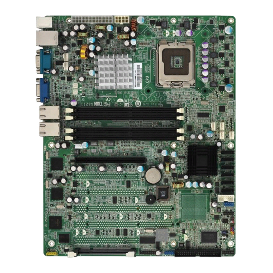
Page 8: Board Image
2.1- Board Image Toledo i3210W S5211 This picture is representative of the latest board revision available at the time of publishing. The board you receive may or may not look exactly like the above picture. http://www.tyan.com... - Page 9 Toledo i3200R S5211-1U This picture is representative of the latest board revision available at the time of publishing. The board you receive may or may not look exactly like the above picture. http://www.tyan.com...
-
Page 10: Block Diagram
2.2 - Block Diagram NOTE: If a PCI-E x16 VGA adapter is inserted into PCI-E slots, the VGA card will only work at PCI-E x1 speed; this is a chipset limitation. Toledo i3210W S5211 http://www.tyan.com... - Page 11 NOTE: If a PCI-E x16 VGA adapter is inserted into PCI-E slot, the VGA card will only work at PCI-E x1 speed; this is a chipset limitation. Toledo i3200R S5211-1U http://www.tyan.com...
-
Page 12: Board Parts, Jumpers And Connectors
This diagram is representative of the latest board revision available at the time of publishing. The board you receive may not look exactly like the above diagram. Jumper Legend OPEN - Jumper OFF, without jumper cover CLOSED – Jumper ON, with jumper cover http://www.tyan.com... - Page 13 12-pin Front Panel Connector TYFP2 (J22) (reserved for OEM only) LCM Connector (reserved for OEM only) IPMB (J4) IPMB Connector ® IPMI Connector (for TYAN M3295/M3296) Riser Power Connector Barebone Fan Connector (reserved for OEM only) PCI-X Speed Select Jumper CMOS (JP3) Clear CMOS Jumper http://www.tyan.com...
- Page 14 FAN6 FAN5 FAN2 FAN1 FAN4 FAN3 TYFP1 TYFP2 http://www.tyan.com...
- Page 15 HDD LED, power LED, power button, and reset button. Chassis Intrusion # SMBUS Clock SMBUS Data Key Pin +5VSB Warning LED - Warning LED+ Reset SW+ PWR SW # PWR LED- HDD LED- PWR LED+ HDD LED+ http://www.tyan.com...
- Page 16 COM2 USB1 IPMB USB2 http://www.tyan.com...
- Page 17 Use these headers to connect to the USB devices via the enclosed USB cable. COM2 (J19): COM2 Header Use these pin definitions to connect a port to COM2. ® *TYAN does not provide cable for this header. It is designed for OEM use only Signal Signal...
- Page 18 SATA0 SATA1 SATA2 SATA3 SATA4 SATA5 CMOS http://www.tyan.com...
- Page 19 AC source Use jumper cap to close Pin 2 and 3 for several seconds to Clear CMOS Clear Replace jumper cap to close Pin 1 and 2 Reconnect the power supply to the AC source Power on system http://www.tyan.com...
-
Page 20: Tips On Installing Motherboard In Chassis
Some chassis’ include plastic studs instead of metal. Although the plastic studs ® are usable, TYAN recommends using metal studs with screws that will fasten the motherboard more securely in place. Below is a chart detailing what the most common motherboard studs look like and how they should be installed. -
Page 21: Installing The Memory
2.5 - Installing the Memory Before installing memory, ensure that the memory you have is compatible with the motherboard and processor. Only DDRII-800/667 DIMM modules are required. ® Check the TYAN Web site at: www.tyan.com for details of the type of memory recommended for your motherboard. - Page 22 The total amount of memory populated in each channel is not the same. For example, Channel A has one 256MB DIMM and Channel B has two 256MB DIMMs. Another example is Channel A has two 256MB DIMMs and Channel B has two 512MB DIMMs. http://www.tyan.com...
- Page 23 Align the memory module with the socket. The memory module is keyed to fit only one way in the socket. Key slot Seat the module firmly into the socket by gently pressing down until it sits flush with the socket. The locking levers pop up into place. http://www.tyan.com...
-
Page 24: Installing The Processor And Cooling Fan
2.6 - Installing the Processor and Cooling Fan Your S5211/S5211-1U supports the latest processor technologies from Intel. Check ® the TYAN website for latest processor support: http://www.tyan.com Processor Installation (LGA 775 Socket) The processor should be installed carefully. Make sure you are wearing an antistatic strap and handle the processor as little as possible. - Page 25 Follow these instructions to install the heatsink shown. Take out the heatsink from the package. Turn the heatsink upside down and you can see that the heatsink has already applied a layer of thermal compound. thermal compound http://www.tyan.com...
- Page 26 Turn the board upside down and insert the heat sink spring mechanism as shown. Align the heatsink with the four holes around the processor socket. Press the heatsink down until the four screws are securely seated in the holes. Use screw drive to secure the four screws. http://www.tyan.com...
-
Page 27: Attaching Drive Cables
TIP: Pin 1 on the IDE cable (usually designated by a colored wire) faces the drive’s power connector. Attaching Serial ATA Cables The Toledo i3210W (S5211) and Toledo i3200R (S5211-1U) is also equipped with 6 Serial ATA (SATA) channels. Connections for these drives are also very simple. -
Page 28: Installing Add-In Cards
Simply find the appropriate slot for your add-in card and insert the card firmly. Do not force any add-in cards into any slots if they do not seat in place. It is better to try another slot or return the faulty card rather than damaging both the motherboard and the add-in card. http://www.tyan.com... -
Page 29: Installing Optional So-Dimm Modules
2.9 - Installing Optional SO-DIMM modules Your S5211/S5211-1U motherboard is equipped with an optional proprietary SO- ® DIMM connector. The 200-pin vertical SO-DIMM connector can be used for TYAN ® M3295/M3296 expansion cards to provide such features as additional TYAN ®... -
Page 30: Connecting External Devices
10/100/1000 Mbps LAN Link/Activity LED Scheme Left LED Right LED Link Slow Blinking Green 10 Mbps Active Blinking Green Link Slow Blinking Green Green 100 Mbps Active Blinking Green Green Link Slow Blinking Green Orange 1000 Mbps Active Blinking Green Orange No Link http://www.tyan.com... -
Page 31: Installing The Power Supply
In the rare circumstance that you have experienced difficulty, you can find help by asking your vendor for assistance. If they are not available for assistance, please find setup information and documentation online at our website or by calling your vendor’s support line. http://www.tyan.com... - Page 32 NOTE http://www.tyan.com...
-
Page 33: Chapter 3: Bios Setup
The table below shows how to use the setup program with the keyboard. Function Moves from one selection to the next Left/Right Arrow Keys Changes from one menu to the next Up/Down Arrow Keys Moves between selections Enter Opens highlighted section PgUp/PgDn Keys Changes settings. http://www.tyan.com... - Page 34 Chipset section unless you are sure of the outcome. ® TYAN or your system manufacturer has carefully chosen the chipset defaults for best performance and reliability. Even a seemingly small change to the Chipset setup options may cause the system to become unstable or unusable.
-
Page 35: Main Bios Setup
Use this menu to configure security settings for your system. Power Use this menu to configure power options for your system. Boot Use this menu to configure boot options for your system. Exit This contains the various BIOS exit options. http://www.tyan.com... -
Page 36: Main Menu
HHHours (24hr. format): MMMinutes : SSSeconds System Date: Adjusts the system date. MMMonths : DDDays : YYYYYears Installed Memory/Available to OS/Used by devices This displays the amount of system memory allocated to OS or used by devices. (read only) http://www.tyan.com... - Page 37 All newer hard disks do in fact support LBA, and when auto detected by a BIOS supporting LBA, will be set up to use that mode. http://www.tyan.com...
- Page 38 DMA protocols, it can be added to many existing computers by installing an Ultra DMA/33 Peripheral Component Interconnect adapter card. Ultra DMA uses the same 40-pin Integrated Drive Electronics interface cable as PIO and DMA. Options: Disabled / Mode 0 / Mode 1 / Mode 2 / Mode 5 http://www.tyan.com...
- Page 39 As such, it would be a waste of L2 cache bandwidth to cache the video BIOS instead of data that are more critical to the system's performance. In addition, if any http://www.tyan.com...
- Page 40 Options: Write Through / Write Back Cache Extended Memory Area Control caching of system memory above one megabyte. Options: Write Through / Write Back Cache A000-AFFF~ Cache DC00-DFFF Control caching of the memory blocks. Options: Disabled / Write Back/ Write Through / Write Protect http://www.tyan.com...
- Page 41 When Summary Screen is Enabled (the default), a Phoenix BIOS Setup Utility summary screen appears during system boot after the power-on self-test (POST). The summary screen lists many of the system setup settings. When this option is set to Disabled, the summary screen does not appear. Options: Enabled / Disabled http://www.tyan.com...
- Page 42 Options: No Delay / 40 Sec / 60 Sec / 80 Sec / 100 Sec / 120 Sec / 140 Sec / 160 Sec Endless Boot If enabled, system will only try to boot up from PXE. If PXE boot is failed, system will keep on trying until reaching PXE server. Options: Enabled / Disabled http://www.tyan.com...
-
Page 43: Advanced Menu
Please note that the BIOS will automatically reset it to the default setting of No after reconfiguring the new ESCD. So, there is no need for you to manually disable this feature after rebooting. Options: Yes / No http://www.tyan.com... - Page 44 Options: DOS / Other Route Port 80h cycles to This feature allows you to route Port 80h I/O cycles to LPC or PCI bus. Options: PCI / LPC Legacy USB Support: Enables support for legacy USB. Options: Enabled / Disabled http://www.tyan.com...
- Page 45 Options: 2 Mins / 4 Mins / 6 Mins / 8 Mins / 10 Mins Memory Reclaiming It allows you to enable or disable the system memory remap function. Options: Enabled / Disabled ECC Error Condition Select ECC Error Condition to be detected. Options: Multiple bit / None / Single bit / Both http://www.tyan.com...
- Page 46 This item allows you to enable the SATA AHCI functionality. Options: Disabled / Enabled SATA AHCI Legacy Enable [Enabled]: SATA and PATA drives are auto-detected and placed in Legacy Mode. [Disabled]: SATA and PATA drives are auto-detected and placed in Native IDE mode. Options: Disabled / Enabled http://www.tyan.com...
- Page 47 Controls the USB device by selecting the listed USB functions. Options: Fun #0, 1, 2, 3, 7 / Disabled USB Dev #26 Controls the USB device by selecting the listed USB functions. Options: Fun #0, 1, 2, 7 / Disabled http://www.tyan.com...
- Page 48 3.4.1.1.1 LAN Control Sub-Menu LAN1 / LAN2 Enables the onboard LAN controller. Options: Enabled / Disabled Option ROM Scan Initializes device expansion ROM. Options: Disabled / Enabled http://www.tyan.com...
- Page 49 3.4.1.2 PCI Express Sub-Menu PCI Express Base Address / GMCH Base Address / DMI Base Address / Egress Port Base Address / ICH9 RCB Base Address Read only. http://www.tyan.com...
- Page 50 Options: Auto / Enabled / Disabled / Debug PEG Port #1(#2) Enabled / PEG Port #1 (#2) Number / PEG #1 (#2) Width / PEG Port #1 (#2) Slot Number / PEG #1 (#2) Power Limit / PEG #1 (#2) Slot Card Detect Read only. http://www.tyan.com...
- Page 51 Multiple Core Processor. Only single thread and core is enabled. Options: Disabled / Enabled Machine Checking Microsoft windows & new linux kernel support the Machine check architectures. This enables Machine check exception reporting for all implementation-defined errors. Options: Enabled / Disabled http://www.tyan.com...
- Page 52 Throttling reduces the number of processing cycles, thereby diminishing the heat dissipation of the CPU. This cools the unit. Once the CPU has reached a safe operating temperature, thermal throttling is automatically disabled, and normal full speed processing begins again. Options: GV1/GV3 only / Disabled http://www.tyan.com...
- Page 53 This defines how the serial port A/B is detected and configured. Options: Disabled / Enabled / Auto Base I/O Address: Set the base I/O address for serial port A/B. Options: 3F8 / 2F8 / 3E8 / 2E8 Interrupt: Set the interrupt for serial port A/B. Options: IRQ3 / IRQ4 http://www.tyan.com...
- Page 54 Select [Enabled] to allow logging of DMI events. Options: Enabled / Disabled Mark DMI Events as Read Press [Enter] to mark DMI events as read. Clear all DMI Event logs When set to [Enabled], BIOS event log will be cleared. Options: Disabled / Enabled http://www.tyan.com...
- Page 55 Options: Enabled / Disabled PWM Duty Cycle This item allows you to set minimum PWM Duty Cycle. Options: 0% / 30% / 40% / 50% Note: This item is usually hidden and will appear when Auto Fan Control is set to [Enabled]. http://www.tyan.com...
- Page 56 3.4.5.1 Voltage Monitoring Sub-Menu All items on this submenu can not be modified in user mode. Read only. http://www.tyan.com...
- Page 57 Options: Disabled / Enabled BIOS POST Errors Enabled -> BIOS will halt & display error message if there is any POST error . Disabled -> BIOS will not halt if there is any POST error. Options: Disabled / Enabled http://www.tyan.com...
- Page 58 Options: 10 - 255 Time Out Action Select what to do when Watchdog time out. Options: No Action / System Reset 3.4.6.1 System Event Log Sub-Menu All items on this submenu can not be modified in user mode. Read only. http://www.tyan.com...
- Page 59 3.4.6.2 System Event Log (list mode) Sub-Menu All items on this submenu can not be modified in user mode. Read only. http://www.tyan.com...
- Page 60 3.4.6.3 Realtime Sensor Data Sub-Menu All items on this submenu can not be modified in user mode. Read only. http://www.tyan.com...
- Page 61 Console Connection It indicates whether the console is connected directly to the system or a modem is used to connect. Options: Direct / via Modem Continue C.R. after POST Enables Console Redirection after OS has loaded. Options: Off / On http://www.tyan.com...
-
Page 62: Security Menu
When enabled, the system will ask for a password at every boot. The system will continue booting only if the correct password is entered. If the wrong password is entered three times, the system will automatically shut down. Options: Disabled / Enabled http://www.tyan.com... -
Page 63: Power Menu
[Disabled]: keeps the power off until the power button is pressed. Options: Power On / Stay Off / Last State Chassis Intrusion Detect This feature is used to enable/disable the function: when chassis open event is detected, BIOS will record the event. Options: No / Yes http://www.tyan.com... -
Page 64: Boot Menu
3.7 Boot Use this screen to select options for the Boot Settings Configuration. Boot Priority Order It shows the boot priority for installed devices. Excluded from boot order It lists devices to be excluded from boot order. http://www.tyan.com... -
Page 65: Exit Menu
This exits BIOS setup after discarding the changes made. Load Setup Defaults This loads the factory default values. Discard Changes This discards all changes made without exiting BIOS setup. Save Changes This saves all changes made without exiting BIOS setup. http://www.tyan.com... - Page 66 NOTE http://www.tyan.com...
-
Page 67: Chapter 4: Diagnostics
Every BIOS file is unique for the motherboard it was designed for. For Flash Utilities, BIOS downloads, and information on how to properly use the Flash Utility ® with your motherboard, please check the TYAN web site: http://www.tyan.com/ NOTE: Please be aware that by flashing your BIOS, you agree that in the event of a BIOS flash failure, you must contact your dealer for a replacement BIOS. -
Page 68: Phoenix Bios Post Code
Clear 512 KB base RAM Jump to UserPatch1 1-3-4-1. RAM failure on Configure advanced cache address registers 1-3-4-3. RAM failure on Initialize Multi Processor data bits of low byte of APIC memory bus Enable cache before Enable external and CPU http://www.tyan.com... - Page 69 (optional) Initialize local-bus hard-disk Initialize notebook docking controllers (optional) Jump to UserPatch2 Initialize notebook docking late Build MPTABLE for multi- Force check (optional) processor boards Install CD ROM for boot Extended checksum (optional) Clear huge ES segment Unknown Interrupt http://www.tyan.com...
- Page 70 Initialize PIC and DMA Initialize System Management Mode Initialize Memory type Output one beep before boot Initialize Memory size Boot to Mini DOS Shadow Boot Block Clear Huge Segment System memory test Boot to Full DOS Initialize interrupt vectors http://www.tyan.com...
-
Page 71: Appendix: Smdc Information
Platform Management Bus (IPMB), Emergency Management Port (EMP) and standard IPMI-Over-LAN communication as defined in latest IPMI 1.5 specification. ® ® TYAN SMDC is compatible with all IPMI-compliance software as well as TYAN System Operator (TSO) software package. ® By adding SMDC, TYAN ’s server board becomes a highly manageable and IPMI... -
Page 72: How Smdc And Tso Work
Features of Tyan® Server Management Monitor various system components remotely - such as fans, processor temperature, and more Remote power on and power off Console redirect -the ability to view system remotely Alert and error actions -such as audible beep, e-mail, power down and reboot... -
Page 73: Glossary
While this improves system performance --- reading to or writing from a disk drive a single time is much faster than doing so repeatedly --- there is also the possibility of losing your data should the system crash. Information stored in a buffer is temporarily stored, not permanently saved. http://www.tyan.com... - Page 74 DMA (Direct Memory Access): channels that are similar to IRQs. DMA channels allow hardware devices (like soundcards or keyboards) to access the main memory without involving the CPU. This frees up CPU resources for other tasks. As with http://www.tyan.com...
- Page 75 EEPROM (Electrically Erasable Programmable ROM): also called Flash BIOS, is a ROM chip which can, unlike normal ROM, be updated. This allows you to keep up with changes in the BIOS programs without having to buy a new chip. TYAN’s BIOS updates can be found at http://www.tyan.com ESCD (Extended System Configuration Data): a format for storing information about Plug-n-Play devices in the system BIOS.
- Page 76 IDE drives. These modes use the CPU for data transfer (in contrast, DMA channels do not). PCI refers to the type of bus used by these modes to communicate with the CPU. PCI-to-PCI bridge: allows you to connect multiple PCI devices onto one PCI slot. http://www.tyan.com...
- Page 77 SATA (Serial ATA): is an evolutionary replacement for the Parallel ATA physical storage interface. Serial ATA is a drop-in solution in that it is compatible with today’s software and operating systems. It will provide for systems which are easier to http://www.tyan.com...
- Page 78 It is fast enough to support video transfer, and is capable of supporting up to 127 daisy-chained peripheral devices. VGA (Video Graphics Array): the PC video display standard V-SYNC: controls the vertical scanning properties of the monitor. http://www.tyan.com...
-
Page 79: Technical Support
1. See the beep codes section of this manual. ® 2. See the TYAN website for FAQ’s, bulletins, driver updates, and other information: http://www.tyan.com ® 3. Contact your dealer for help BEFORE calling TYAN ® 4. Check the TYAN user group: alt.comp.periphs.mainboard.TYAN Returning Merchandise for Service During the warranty period, contact your distributor or system vendor FIRST for any product problems. - Page 80 Danger of explosion if battery is incorrectly replaced. Replace only with the same or equivalent type recommended by manufacturer. Dispose of used battery according to manufacturer instructions and in accordance with your local regulations. Document #: D1890-140 http://www.tyan.com...
Need help?
Do you have a question about the Toledo i3210W and is the answer not in the manual?
Questions and answers