
Subscribe to Our Youtube Channel
Related Manuals for Ametek SWI L500


Summary of Contents for Ametek SWI L500
- Page 1 L500 LIQUID LEVEL FLOAT SWITCH INSTALLATION AND OPERATIONS MANUAL Single or Multi-Point, Vertically-Mounted Liquid Level Float Switch ISO 9001:2008 CERTIFIED...
- Page 2 This manual provides information on the Notice of Copyright and Limitations L500 Single or Multi-Point Liquid Level Float Switch Copyright ©2022 AMETEK Magnetrol USA, LLC It is important that all instructions are read carefully All rights reserved. and followed sequentially. Detailed instructions are...
- Page 3 L500 LIQUID LEVEL FLOAT SWITCH Single or Multi-Point, Vertically-Mounted TABLE OF CONTENTS 1.0 Installation 1.1 Unpacking................4 1.2 Before You Begin..............4 1.2.1 Site Preparation............4 1.2.2 Equipment and Tools..........4 1.3 Mounting................5 1.3.1 Threaded Mounting............5 1.4 Wiring..................5 2.0 Preventative Maintenance 2.1 What To Do................6 2.1.1 Inspect Entire Unit Periodically.........6 2.1.2 Inspect Connections Monthly........6 2.1.3 Keep Unit Clean............6...
- Page 4 1.0 COMPLETE INSTALLATION This section provides detailed procedures on properly installing the L500 Single or Multi-Point Liquid Level Float Switch. CAUTION! IF THE EQUIPMENT IS USED IN A MANNER NOT SPECIFIED BY THE MANUFACTURER, PROTECTION PROVIDED BY THE EQUIPMENT MAY BE IMPAIRED. CAUTION! THIS UNIT CONTAINS REED SWITCHES THAT MAY BE PERMANENTLY DAMAGED BY MECHANICAL SHOCK OR VIBRATION.
- Page 5 1.3 MOUNTING The L500 Single or Multi-Point Liquid Level Float Switch is available in a variety of threaded and flanged mountings. These devices are meant to be installed on the top or bottom of a process tank. They should be mounted in an area free of turbulence or direct streams.
- Page 6 2.0 PREVENTATIVE MAINTENANCE Periodic inspections are necessary to maintain the proper functionality of the L500 Single or Multi-Point Liquid Level Switch. The switch is a safety device that protects the equipment it serves. A systematic program of preventative maintenance should be implemented at the time of installation. If the following instructions are completed routinely, the switch will provide continuous, reliable protection.
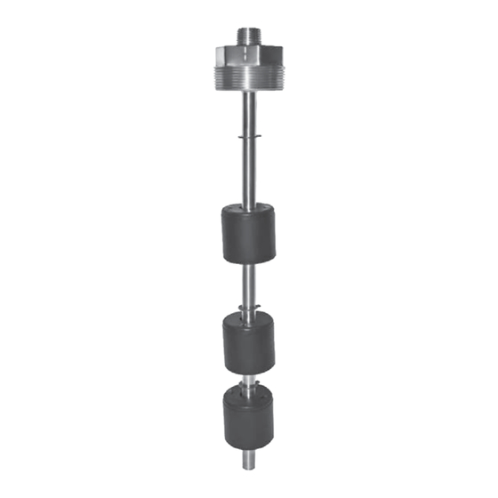
- Page 7 3.0 REFERENCE INFORMATION This section illustrates an overview of the L500 Single or Multi-Point Liquid Level Switch, as well as information on troubleshooting common problems, agency approval listings, and detailed physical, functional and performance specifications. 3.1 DESCRIPTION The wider displacement L500 Single or Multi-Level Switch is designed to monitor up to six levels on a single device.
- Page 8 3.3.2 Unit Causes If a thorough inspection of any external causes fails to locate the problem, proceed to an inspection of the unit, itself. DISCONNECT POWER TO THE LEVEL SWITCH BEFORE PROCEEDING. SYMPTOM PROBLEM SOLUTION THE UNIT IS UNRESPONSIVE. ELECTRICAL FAILURE. ELECTRICAL CONTINUITY CHECKER TO DETERMINE IF THE...
- Page 9 3.5 SPECIFICATIONS 3.5.1 Physical Specifications FLOAT MATERIAL DIMENSIONS TEMPERATURE PRESSURE MIN. SPECIFIC GRAVITY Polypropylene (Hollow) 1.875” x 1.906” -40° to +150° F 50 PSIG 0.48 PVC (Hollow) 1.875” x 1.906” -40° to +150° F 50 PSIG 0.69 316 Stainless Steel 1.50”...
- Page 10 3.5.4 Dimensional Specifications Actuation Level Dimensions L500 1 ½” 3” 2” ¼” Area Definitions L500 Adjustable DEFINITION Minimum Distance from Actuation Point to Inside Surface of Tank or Mounting Pad Minimum Distance Between Actuation Levels Minimum Distance from End of Unit to Lowest Actuation Level Minimum Distance Between Points When A Single Float is Used to Activate 2 Switches*...
- Page 11 3.7 NOTES L500 SINGLE OR MULTI-POINT LIQUID LEVEL FLOAT SWITCH...
- Page 12 ASSURED QUALITY & SERVICE COST LESS Service Policy Return Material Procedure Owners of Solutions With Innovation products may In order to efficiently process any returned materials, it is essential that a Return Material Authorization (RMA) number request a return of the product, or any part of the product for complete rebuilding or replacement.
Need help?
Do you have a question about the SWI L500 and is the answer not in the manual?
Questions and answers