Table of Contents
Advertisement
Quick Links
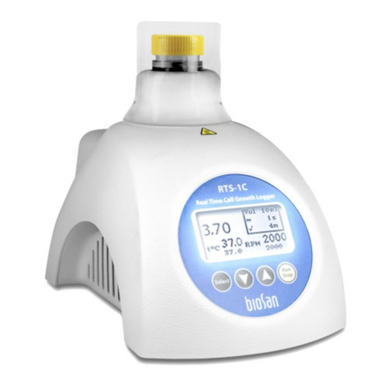
Real Time Cell Growth Logger RTS-1C
Periodical maintenance
Real Time Cell Growth Logger RTS-1C does not require periodical technical
maintenance, except cleaning.
Cleaning. Standard ethanol (up to 75%) or any other cleaning liquids can be used for
cleaning and disinfecting of the device, if it does not contain any strong organic
solvents (such as acetone, toluene or benzene).
The following spare parts are available for Cell Growth Logger RTS-1C:
No.
1
Switch
2
Power Socket
3
USB Connector Board U231
4
Control Board
5
LCD Board
6
Microprocessor main
6
Microprocessor display PIC18F2520
7
Button Board
8
Casing
9
Power Board
10 Motor
11 Fan
12 Peltier element
13 Detector Board
14 Thermosensor
15 LED
RTS-1C Service Manual - V.3A01
Service Manual for
Spare part
H8600VB1
HEBL 2,1mm
MASTR_GRAPH
BG1286 4EFPHBn207 BS-010160-S02
PIC18F2520
BUTM1
RTS-1C
MDRV7
FL42BLS01
ME70201V1
2TM-127-63-6.5MS
PH3
DS18B20
L-53SF7C
Version 1 - February 2015
Marking
BS-000000-S02
BS-000000-S03
BS-000000-S83
BS-010160-S01
BS-010160-S06
BS-010160-S07
BS-010160-S04
BS-010160-S13
BS-010160-S03
BS-010160-S08
BS-010160-S11
BS-010160-S12
BS-010160-S05
BS-010160-S09
BS-010160-S10
Article
Page 1
Advertisement
Table of Contents

Related Manuals for Biosan RTS-1C


Summary of Contents for Biosan RTS-1C
- Page 1 Service Manual for Real Time Cell Growth Logger RTS-1C Periodical maintenance Real Time Cell Growth Logger RTS-1C does not require periodical technical maintenance, except cleaning. Cleaning. Standard ethanol (up to 75%) or any other cleaning liquids can be used for cleaning and disinfecting of the device, if it does not contain any strong organic solvents (such as acetone, toluene or benzene).
- Page 2 5. Unscrew the two screws (fig.3/10) and release the power wires from the Power Board. 6. Disconnect the wire (fig.3/11) and pull out motor assembly. Disassembling is applied to all replacements mentioned below. Not used scheme.1 RTS-1C Service Manual - V.3A01 Version 1 - February 2015 Page 2...
- Page 3 – disconnect the wire terminal from the Button Board; – unscrew the two screws on the Button Board (fig.4/2); – replace the Button Board; – re-assemble the unit. RTS-1C Service Manual - V.3A01 Version 1 - February 2015 Page 3...
- Page 4 – disconnect the Detector Board wire (fig.8/1) from the power board; – unscrew the three screws (fig.8/2) and remove the Detector Boar; fig.7 – replace the Detector Board; – re-assemble the unit. RTS-1C Service Manual - V.3A01 Version 1 - February 2015 Page 4...
- Page 5 7. Press ‡ button and ”0.00” number will appear and blink on the display. 8. Wait 15 seconds and press ˆ button. 9. Device is now calibrated and will make one verification measurement RTS-1C Service Manual - V.3A01 Version 1 - February 2015 Page 5...
- Page 6 RTS-1C Service Manual - V.3A01 Version 1 - February 2015 Page 6...
Need help?
Do you have a question about the RTS-1C and is the answer not in the manual?
Questions and answers