Sign In
Upload
Download
Table of Contents
Contents
Add to my manuals
Delete from my manuals
Share
URL of this page:
HTML Link:
Bookmark this page
Add
Manual will be automatically added to "My Manuals"
Print this page
×
Bookmark added
×
Added to my manuals
Manuals
Brands
Biosan Manuals
Laboratory Equipment
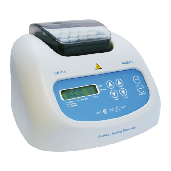
CH-100
Operating manual
Biosan CH-100 Operating Manual
Heating/cooling systems
Hide thumbs
1
Table Of Contents
2
3
4
5
6
7
8
9
10
11
12
13
14
15
16
page
of
16
Go
/
16
Contents
Table of Contents
Bookmarks
Table of Contents
Table of Contents
About this Edition of the Operating Manual
Safety Precautions
General Information
Getting Started
Operation
Calibration
Specification
Maintenance
Warranty and Claims. Registration
EU Declaration of Conformity
Advertisement
Quick Links
1
Maintenance
Download this manual
Table of
Contents
Previous
Page
Next
Page
1
2
3
4
5
Advertisement
Table of Contents
Need help?
Do you have a question about the CH-100 and is the answer not in the manual?
Ask a question
Questions and answers
Related Manuals for Biosan CH-100
Laboratory Equipment Biosan CH 3-150 Operating Manual
Heating/cooling systems (16 pages)
Laboratory Equipment Biosan RTS-1 User Instructions
Personal bioreactor (24 pages)
Laboratory Equipment Biosan Automatic Luminescence Analyser ALA1/4 Operating Manual
Multichannel automatic (12 pages)
Laboratory Equipment Biosan DEN-1 User Instructions
Mcfarland densitometer (16 pages)
Laboratory Equipment Biosan DEN 1B Operating Manual
Densitometer suspension turbidity detector (16 pages)
Laboratory Equipment Biosan IW-8 User Instructions
Intelispeed washer (28 pages)
Laboratory Equipment biosan WB-4MS User Instructions
Stirred water bath (12 pages)
Laboratory Equipment bioSan UVT-B-AR Operating Manual
Dna/rna uv-cleaner box (16 pages)
Laboratory Equipment Biosan UVC-AR User Instructions
Dna/rna uv-cleaner boxes (16 pages)
Laboratory Equipment Biosan RTS-1C Service Manual
Real time cell growth logger (6 pages)
Laboratory Equipment bioSan MMS-3000 User Instructions
Magnetic stirrers (12 pages)
Laboratory Equipment bioSan TS-100 Operating Manual
Thermo-shakers for microtubes and pcr plates (16 pages)
Laboratory Equipment Biosan S-Bt Service Manual
Compact co incubator (16 pages)
Laboratory Equipment bioSan LMC-4200R User Instructions
Laboratory centrifuges (16 pages)
Laboratory Equipment Biosan RCP-24 User Instructions
Reciprocal laboratory homogenizer (16 pages)
This manual is also suitable for:
Ch 3-150
Table of Contents
Print
Rename the bookmark
Delete bookmark?
Delete from my manuals?
Login
Sign In
OR
Sign in with Facebook
Sign in with Google
Upload manual
Upload from disk
Upload from URL


Need help?
Do you have a question about the CH-100 and is the answer not in the manual?
Questions and answers