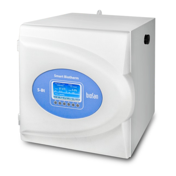
Summary of Contents for Biosan S-Bt
- Page 1 Service Manual for Compact CO incubator S-Bt S-Bt Service Manual - V.1AW Version 1 - October 2017 Page 1...
- Page 2 Maintanence 1. If the unit requires maintenance, disconnect the unit from the mains and contact Biosan or your local Biosan representative. 2. All maintenance and repair operations must be performed only by qualified and specially trained personnel. 3. Regular service schedule:...
- Page 3 1. While in menu hold two right buttons for 5 sec. to enter the service mode (unlock grey menu items). 2. To exit service mode hold two right buttons for 5 sec. or exit from menu to main display. S-Bt Service Manual - V.1AW Version 1 - October 2017 Page 3...
- Page 4 010s Dosage Coef. 1/020 (Preset) 1/020 1/020 1/001 1/001 Recovery time 12 min 3 min 18 min 2 min 45 sec Possible excess 5.00% 5.10% 5.00% 5.10% 5.80% S-Bt Service Manual - V.1AW Version 1 - October 2017 Page 4...
- Page 5 The following spare parts are available for S-Bt: Spare part Marking Article Hydrophobic filter BS-010425-S35 Access port seal Foamed PE (set of 5) BS-010425-S03 Fuse FSMO 3,15A BS-000000-S06 UV lamp TUV-6W T5 BS-010425-S04 Battery CR 2032 (Lithium Battery) BS-010425-S16 Wireless Interface Board...
- Page 6 – unscrew the four screws (fig.5/5) and gently pull out Control Board fig.4 from LCD interface board pin socket; – replace the Control Board, install new battery or take from previous board S-Bt Service Manual - V.1AW Version 1 - October 2017 Page 6...
- Page 7 – replace the Humidity Sensor assembly and re-assemble the unit; Note: It is important to install new sensor PCB in vertical position as Door temperature sensor shown in fig.11/2. fig.8 S-Bt Service Manual - V.1AW Version 1 - October 2017 Page 7...
- Page 8 ) and release Power Socket; – remove fuses (see fuse replacement); – replace the Power socket, install fuses and re-assemble the unit. Sensor interface board fig.11 S-Bt Service Manual - V.1AW Version 1 - October 2017 Page 8...
- Page 9 – unscrew the five screws and release Transformer wires from wire terminal (fig.17/1); – unscrew the screw (fig.17/2) and release the Transformer; Chamber cover removed – replace the Transformer and re-assemble the unit. fig.15 S-Bt Service Manual - V.1AW Version 1 - October 2017 Page 9...
- Page 10 – pull out Open Door Sensor from the slot (fig.19/1); – clean excess silicone; – replace Open Door Sensor, fix it in the slot using silicone; – re-assemble the unit. Working chamber removed fig.19 S-Bt Service Manual - V.1AW Version 1 - October 2017 Page 10...
- Page 11 – remove appropriate temperature sensor (see top, bottom, left, right temperature sensor replacement); – tear off appropriate Heater (fig.20/1); – replace the Heater and re-assemble the unit. S-Bt Service Manual - V.1AW Version 1 - October 2017 Page 11...
- Page 12 Connect the live and neutral pins of the power supply plug together. Use a 500V insulation resistance tester and measure the insulation resistance between the earth and live/neutral pins. This should be greater than 2 Mohm. S-Bt Service Manual - V.1AW Version 1 - October 2017 Page 12...
- Page 13 S-Bt Service Manual - V.1AW Version 1 - October 2017 Page 13...
- Page 14 S-Bt Service Manual - V.1AW Version 1 - October 2017 Page 14...
- Page 15 DC 12V Battery CR 2032 (Lithium Battery) X1...X2 G5 Lampholders T5 MOLEX - 22-01-2045 - CRIMP HOUSING, 2.54MM, 4WAY MULTICOMP-MC6FD016-30P1SOCKET,IDC,S/RELIEF, 16W MULTICOMP MC6FD010-30P1, 6F Receptacle, 10, 2.54 mm S-Bt Service Manual - V.1AW Version 1 - October 2017 Page 15...
- Page 16 • Up to 100 meter range Full datasheet available at: http://ww1.microchip.com/downloads/en/devicedoc/50002280a.pdf RN41-I/RM details: RN41: Device: - UART, Ceramic Chip Antenna I: Temperature Range: -40°C to +85°C Radio Module, latest firmware version 6.30 S-Bt Service Manual - V.1AW Version 1 - October 2017 Page 16...


Need help?
Do you have a question about the S-Bt and is the answer not in the manual?
Questions and answers