ATEN KE6900 User Manual
Dvi kvm over ip extender
Hide thumbs
Also See for KE6900:
- User manual (250 pages) ,
- User manual (142 pages) ,
- User manual (470 pages)
Table of Contents
Advertisement
Quick Links
Download this manual
See also:
User Manual
Advertisement
Table of Contents

Subscribe to Our Youtube Channel
Related Manuals for ATEN KE6900


Summary of Contents for ATEN KE6900
- Page 1 DVI KVM Over IP Extender KE6900 / KE6940 User Manual Lite Edition www.aten.com...
-
Page 2: Fcc, Ce Information
KE6900 / KE6940 Lite User Manual FCC, CE Information FEDERAL COMMUNICATIONS COMMISSION INTERFERENCE STATEMENT: This equipment has been tested and found to comply with the limits for a Class A digital device, pursuant to Part 15 of the FCC Rules. These limits are designed to provide reasonable protection against harmful interference when the equipment is operated in a commercial environment. -
Page 3: User Information
KE6900 / KE6940 Lite User Manual User Information Online Registration Be sure to register your product at our online support center: International http://eservice.aten.com Telephone Support For telephone support, call this number: International 886-2-8692-6959 China 86-10-5255-0110 Japan 81-3-5615-5811 Korea 82-2-467-6789 North America... -
Page 4: Package Contents
Copyright © 2014 ATEN® International Co., Ltd. Manual Part No. F/W Version: Manual Date: 2014-10-24 Altusen and the Altusen logo are registered trademarks of ATEN International Co., Ltd. All rights reserved. All other brand names and trademarks are the registered property of their respective owners. -
Page 5: Table Of Contents
KE6900 / KE6940 Lite User Manual Contents FCC, CE Information......... . ii SJ/T 11364-2006. - Page 6 KE6900 / KE6940 Lite User Manual Default IP Addresses ........24 Chapter 3.
- Page 7 KE6900 / KE6940 Lite User Manual Chapter 7. Device Management Overview ..........57 User Stations.
- Page 8 KE6900 / KE6940 Lite User Manual Appendix Safety Instructions ......... . 97 General .
-
Page 9: About This Manual
KE6900 / KE6940 Lite User Manual About This Manual This User Manual is provided to help you get the most from your KE6900 / KE6940 system. It covers all aspects of installation, configuration and operation. An overview of the information found in the manual is provided below. -
Page 10: Conventions
KE6900 / KE6940 Lite User Manual Conventions This manual uses the following conventions: Monospaced Indicates text that you should key in. Indicates keys you should press. For example, [Enter] means to press the Enter key. If keys need to be chorded, they appear together in the same bracket with a plus sign between them: [Ctrl+Alt]. -
Page 11: Chapter 1 Introduction
(Extender mode), one-to-many (Splitter mode), many-to-one (Switch mode), or many-to-many (Matrix mode). The KE6900 / KE6940 has a local On Screen Display (OSD) on the receiver to configure both units - for easy setup and operation. Using the transmitter and... -
Page 12: Features
KE6900 / KE6940 Lite User Manual Features Remote KVM console access of computers over LAN or Ethernet cable connection Dual console operation – control your system from both the Transmitter and Receiver by USB keyboard, monitor, and mouse RS-232 serial ports –... -
Page 13: Requirements
Chapter 1. Introduction Requirements Console (KE6900) One DVI compatible monitors capable of the highest possible resolution (KE6940) Two DVI compatible monitors capable of the highest possible resolution A USB mouse A USB keyboard Microphone and speakers Computers The following equipment must be installed on each computer that is to be... -
Page 14: Operating Systems
KE6900 / KE6940 Lite User Manual Operating Systems Supported operating systems are shown in the table, below: Version Windows 2000 and higher Linux RedHat 6.0 and higher SuSE 8.2 and higher Mandriva (Mandrake) 9.0 and higher UNIX 4.3 and higher FreeBSD 3.51 and higher... -
Page 15: Components
Chapter 1. Introduction Components KE6900T (Transmitter) Front View Component Description KVM Port Section The USB KVM cable supplied with the package that links the Transmitter to the computer plugs into these ports. RS-232 Serial Port This RS-232 serial port is for connecting to the computer for serial control. -
Page 16: Ke6900T (Transmitter) Rear View
KE6900 / KE6940 Lite User Manual KE6900T (Transmitter) Rear View Component Description Power Jack The cable from the DC Power adapter connects here. Function Switch Use this slide switch to set the unit’s mode to: Config: The device is ready for configuration. -
Page 17: Ke6900R (Receiver) Front View
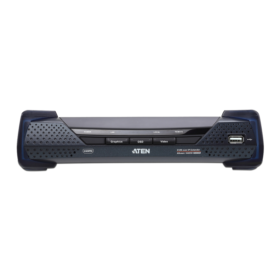
Chapter 1. Introduction KE6900R (Receiver) Front View POWER REMOTE LOCAL Graphics Video Component Description Power LED Lights blue to indicate the module is turned on. LAN LED Lights to indicate the network status: Lights Green when connected to the LAN. Off when not connected to the LAN. -
Page 18: Ke6900R (Receiver) Rear View
KE6900 / KE6940 Lite User Manual KE6900R (Receiver) Rear View Component Description Power Jack The cable from the DC Power adapter connects here. Function Switch Use this slide switch to set the unit’s mode: Configure: The device is ready to configure. -
Page 19: Ke6940T (Transmitter) Front View
Chapter 1. Introduction KE6940T (Transmitter) Front View Component Description KVM Port Section The USB KVM cable supplied with the package that links the Transmitter to the computer plugs into these ports. RS-232 Serial Port This RS-232 serial port is for connecting to the computer for serial control. -
Page 20: Ke6940T (Transmitter) Rear View
KE6900 / KE6940 Lite User Manual KE6940T (Transmitter) Rear View Component Description Power Jack The cable from the DC Power adapter connects here. Function Switch Use this slide switch to set the unit’s mode to: Config: The device is ready to configure. -
Page 21: Ke6940R (Receiver) Front View
Chapter 1. Introduction KE6940R (Receiver) Front View POWER REMOTE LOCAL Graphics Video Component Description Power LED Lights blue to indicate the module is turned on. LAN LED Lights to indicate the network status: Lights Green when connected to the LAN. Off when not connected to the LAN. -
Page 22: Ke6940R (Receiver) Rear View
KE6900 / KE6940 Lite User Manual KE6940R (Receiver) Rear View Component Description Power Jack The cable from the DC Power adapter connects here. Function Switch Use this slide switch to set the unit’s mode: Configure: The device is ready to configure. -
Page 23: Chapter 2. Hardware Setup
Chapter 2 Hardware Setup 1. Important safety information regarding the placement of this device is found on page 97. Please review it before proceeding. 2. Make sure that the power to all devices connected to the installation is turned off. You must unplug the power cords of any computers that have the Keyboard Power On function. - Page 24 KE6900 / KE6940 Lite User Manual 2. Screw the bracket into a convenient location on the rack. Note: These screws are not provided. We recommend that you use M5 x 12 Phillips Type I cross recessed type screws.
-
Page 25: Wall Mounting
Chapter 2. Hardware Setup Wall Mounting For convenience the Transmitter can be mounted to a wall. 1. Using the screws provided in the Mounting Kit, screw the mounting bracket into the bottom of the Transmitter as show in the diagram below: Phillips hex head M3 x 8 2. -
Page 26: Setting Up A Point-To-Point Installation
KE6900 / KE6940 Lite User Manual Setting Up a Point-to-Point Installation Setting up the KE6900 / KE6940 system in a point-to-point configuration is simply a matter of plugging in the cables. Note: In a point-to-point configuration, no administrator setup is necessary. -
Page 27: Point-To-Point Installation 1 Of 2
Chapter 2. Hardware Setup Point-to-Point Installation 1 of 2 Cat 5e cable KE6900T Cat 5e cable KE6900R Note: The diagram above shows the KE6900T and KE6900R. The KE6940 installation is the same except that an additional DVI monitor can be connected at each end for a dual-view display setup. -
Page 28: Point-To-Point Installation 2 Of 2
KE6900 / KE6940 Lite User Manual Point-to-Point Installation 2 of 2 KE6900T Local PC USB KVM cable Note: The serial port on the Transmitter (shown above) connects to the computer; the serial port on the Receiver (not shown) connects to a... -
Page 29: Setting Up A Lan Installation
KE6900 / KE6940 devices on the same TCP/IP LAN. Note: 1. The units are preconfigured with factory-default network settings. If you install only one set of KE6900 / KE6940 units, you do not need to change these default network settings. See Default IP Addresses, page 24, for further details. - Page 30 KE6900 / KE6940 Lite User Manual 5. Use a Cat 5e cable to connect the KE6900T / KE6940T’s LAN port to the local area TCP/IP network. 6. Plug the power adapter into an AC source; and plug the other end into the KE6900T / KE6940T’s Power Jack.
-
Page 31: Network Installation Diagram 1 Of 2
Chapter 2. Hardware Setup Network Installation Diagram 1 of 2 Cat 5e cable KE6900T TCP/IP Cat 5e cable KE6900R Note: The diagram above shows the KE6900T and KE6900R. The KE6940 installation is the same except that an additional DVI monitor can be connected at each end for a dual-view display setup. -
Page 32: Network Installation Diagram 2 Of 2
KE6900 / KE6940 Lite User Manual Network Installation Diagram 2 of 2 KE6900T Local PC USB KVM cable Note: The serial port on the Transmitter (shown above) connects to the computer; the serial port on the Receiver (not shown) connects to a... -
Page 33: Network Configuration
IP address, see IP Installer, page 103. Note: 1. Both devices are preconfigured with factory-default network settings. If you install only one set of KE6900 / KE6940 units, you do not need to change these default network settings. See Default IP Addresses, page 24, for further details. -
Page 34: Return
KE6900 / KE6940 Lite User Manual Note: See Default IP Addresses, page 24, for the preconfigured factory-default settings. Subnet Mask – sets the subnet mask for the KE6900 / KE6940. Key in a valid subnet mask value. Note: The default setting is 255.255.255.0 Default Gateway–... -
Page 35: Chapter 3. Osd Operation
Chapter 3 OSD Operation Overview This chapter provides instructions to configure and operate the KE6900 / KE6940 using the local On Screen Display (OSD). To configure the network settings with the OSD, see Network Configuration, page 23. LED Display Both the Transmitter and Receiver have front panel LEDs to indicate their... -
Page 36: Invoking The Osd
KE6900 / KE6940 Lite User Manual Invoking the OSD The On Screen Display (OSD) is a keyboard/mouse-driven application on the receiver used to configure the transmitter and receiver settings. Once the receiver has discovered the transmitter over a network* or direct Ethernet cable connection, you can use the OSD on the receiver to configure the transmitter’s... -
Page 37: Osd Interface
Chapter 3. OSD Operation OSD Interface After you invoke the OSD, the main page appears: Note: A password is required to enter the OSD. The default password is: password. For security purposes, we recommend you change this to something unique. The OSD components are described in the table, below: Item Description... -
Page 38: User Station Configuration
KE6900 / KE6940 Lite User Manual User Station Configuration When you select the User Station radio button and click Configure to login, the Network tab appears: Network The Network tab allows you to configure the User Station’s IP address settings:... -
Page 39: Properties
Chapter 3. OSD Operation Properties The Properties tab allows you to configure the User Station’s extender settings: Item Description Mode Select Extender mode for simple one-to-one (Transmitter to User Station) setups that are managed with the Receiver’s OSD menu. Select Desktop/Matrix mode to manage devices and connections from the Matrix Manager Lite web GUI. - Page 40 KE6900 / KE6940 Lite User Manual Item Description RS232 Settings Configure the serial device settings for the User Station. The default settings are: Baud Rate: 9600 Parity: None Data Bits: 8 bits Stop bits: 1 bit Flow Control: None Enable Media Select which type of media the User Station can stream from Transmitters: Video, Audio, USB, and RS232.
-
Page 41: System
Chapter 3. OSD Operation System The System tab allows you to configure the User Station’s general settings: Item Description Device Enter the Name, Location, and Description of the User Information Station. It also displays the IP Address, MAC Address, F/W Version, Serial Number, and Model Number of the User Station. -
Page 42: Transmitter Configuration
KE6900 / KE6940 Lite User Manual Transmitter Configuration When you select the Transmitter radio button and click Configure to login, the Network tab appears: Network The Network tab allows you to configure the Transmitter’s IP address settings: Item Description IP Installer The IP Installer is an external Windows-based utility for assigning an IP address to the device. -
Page 43: Properties
Chapter 3. OSD Operation Properties The Properties tab allows you to configure the Transmitter’s extender settings: Item Description Mode Select Extender mode for simple one-to-one (Transmitter to User Station) setups that are managed with the Receiver’s OSD menu. Select Desktop/Matrix mode to manage devices and connections from the Matrix Manager Lite web GUI. - Page 44 Select how you want the source device to acquire the display's EDID: Default: EDID is set to the default ATEN configuration. Auto: Checks the EDID of all connected displays and uses the best resolution for all displays.
- Page 45 Chapter 3. OSD Operation Item Description Transmitter To set the Transmitter’s video settings: Video Attributes Video Type: Select the DVI video connector being used by the display: Digital (DVI-D) or Digital (DVI-I). Color Depth: Select the number of bits to use for the color depth: 24, 16, or 8.
-
Page 46: System
KE6900 / KE6940 Lite User Manual System The System tab allows you to configure the Transmitter’s general settings: Item Description Device Enter the Name, Location, and Description of the Transmitter. Information It also displays the IP Address, MAC Address, F/W Version, Serial Number, and Model Number of the Transmitter. -
Page 47: User Preferences
Chapter 3. OSD Operation User Preferences When you select the User Preferences radio button and click Configure to login, the configuration screen appears: Item Description User Password This section allows you to change the OSD password: Change 1. Key in the old password in the Old password field. 2. -
Page 48: Connecting
KE6900 / KE6940 Lite User Manual Connecting If the User Station is set to Extender mode, the video screen of the remote computer will appear automatically when you exit the OSD (tap the Scroll Lock key twice). In Desktop/Matrix mode you will see the System Login... -
Page 49: Connections Page
Chapter 3. OSD Operation Connections Page After you have successfully logged in the Connection Page appears: The Connection Page components are described in the table, below: Item Description Target Name Lists the Target connections available for the User Station. A Target is a defined connection to Transmitters, created in the Device Management tab of the Matrix Manager Lite. - Page 50 KE6900 / KE6940 Lite User Manual Item Description Connect To connect the User Station to a Target, click the access type: Exclusive: The first User Station to access the Target has exclusive control over the Target. No other User Stations can view the Target. The Timeout function does not apply to this setting.
-
Page 51: Profile Page
Chapter 3. OSD Operation Profile Page Click the Profile Page tab and the following screen appears: The Profile Page components are described in the table, below: Item Description Profile Name Lists the Profiles available. Profiles give User Stations access to Targets and allow you to push the connection. - Page 52 KE6900 / KE6940 Lite User Manual This Page Intentionally Left Blank...
-
Page 53: Matrix Manager Lite Installation
Overview The Matrix Manager Lite is a browser based GUI that provides management of KE6900 / KE6940 devices over a network . Download and install the software to begin managing KE6900 / KE6940 devices from a computer using a web browser. - Page 54 Note: The trial software includes full functions to setup and configure single device installations. The trial version will not expire. If you would like to purchase the advanced software, please contact your ATEN reseller. 5. Click the software version you would like to download, then click Save.
-
Page 55: Matrix Manager Installation
Chapter 4. Matrix Manager Lite Installation Matrix Manager Installation The following are instructions to install the lite version of the Matrix Manager software. For computer hardware/software requirements, see Software, page 3. 1. Double click the KeManagerLiteSetup file to start the installation. When the Introduction screen appears, click Next: 2. - Page 56 KE6900 / KE6940 Lite User Manual 3. The Choose Install Folder screen appears: Select where you would like to install the program, and click Next. 4. The Choose Shortcut Folder screen appears: Select where to create shortcuts for the program by selecting the options...
- Page 57 Chapter 4. Matrix Manager Lite Installation 5. The Pre-Installation Summary screen appears: Confirm the settings you’ve selected. If you want to make a change click Previous to go back, or click Install to begin the software installation. 6. When the process is done, the Install Complete screen appears: Click Done.
- Page 58 KE6900 / KE6940 Lite User Manual This Page Intentionally Left Blank...
-
Page 59: Chapter 5. Browser Operation
Chapter 5 Browser Operation Overview The Matrix Manager Lite software can be accessed through most standard web browsers. Once users log in and are authenticated, the browser GUI comes up. This chapter explains the login procedure and web browser components. Logging In To log into the Matrix Manager, do the following: 1. -
Page 60: The Matrix Manager Lite Main Page
KE6900 / KE6940 Lite User Manual The Matrix Manager Lite Main Page After you have successfully logged in, the web browser’s main page appears: Web Components The web components are described in the table, below: Item Description Tab Bar The tab bar contains the Matrix Manager’s main... -
Page 61: Tree View Considerations
Chapter 5. Browser Operation Item Description Interactive Display Panel This is your main work area. The screens that appear reflect your menu choices and Sidebar item selection. Tree View Considerations On some pages there will be a sidebar menu with options that can be expanded: A plus (+) sign in front of an item means that there are additional items nested inside of it. -
Page 62: The Tab Bar
KE6900 / KE6940 Lite User Manual The Tab Bar The functions associated with each of the tabs are explained in the table below: Icon Function Dashboard: The Dashboard is used to view information about current connections, sessions, and device events. The first page provides an overview and the sidebar provides a link to view details about each section. -
Page 63: Chapter 6. Dashboard
Chapter 6 Dashboard Overview The Dashboard tab is used to view events about connections, sessions, and online devices. The Home page provides an overview of the information provided in each section. The Sidebar menu provides a link to each section for a more detailed view of each item. -
Page 64: Active Connections
KE6900 / KE6940 Lite User Manual Active Connections The Active Connections page lets an administrator see the active connections (User Stations connected to Transmitters) and provides information about each of their sessions. The meanings of the headings at the top of the page are straightforward. -
Page 65: Online User Stations
Chapter 6. Dashboard Online User Stations The Online User Stations page lets the administrator see all of the Receivers that are currently available on the network and provides information about each device. The meanings of the headings at the top of the page are straightforward. ID refers to the identification number assigned by the system. -
Page 66: Latest Events
KE6900 / KE6940 Lite User Manual Latest Events The Latest Events page lets the administrator see the most recent Dashboard events that relate to the current connections and sessions, and provides details about each. The meanings of the headings at the top of the page are straightforward. -
Page 67: Overview
Chapter 7 Device Management Overview The Device Management tab contains four menu bar items: User Stations, Transmitters and Profiles. Each page provides a way to add, configure, and managed Transmitters, Receivers, and connections. Before Transmitters and Receivers can be added they must be connected to the network with an IP address. -
Page 68: User Stations
KE6900 / KE6940 Lite User Manual User Stations The User Stations page allows you to add, configure, and delete Receivers. The Sidebar provides two menu options: User Stations and Unmanaged User Stations. Unmanaged User Stations are Receivers on the network that haven’t been added to the Matrix Manager Lite. -
Page 69: Adding A User Station
Chapter 7. Device Management Adding a User Station To add a User Station, do the following: 1. From Unmanaged User Stations, select a User Station and click Add in: or click Search New: You can search for a device by Local, Subnet, or IP address. Select a scope, enter the information and click Search. -
Page 70: Configuring A User Station
KE6900 / KE6940 Lite User Manual Configuring a User Station A User Station’s settings can be modified from the User Stations main page. Changes that are saved are updated on the User Station device across the network. To configure a User Station: 1. - Page 71 Chapter 7. Device Management Item Description Network For dynamic IP address assignment, select the Obtain IP Configuration address automatically radio button. To specify a fixed IP Address, Subnet Mask, and Default Gateway select the Set IP address manually radio button and fill in the fields with values appropriate for your network.
- Page 72 KE6900 / KE6940 Lite User Manual Item Description RS-232 Settings Configure the settings for the serial device the User Station will be connecting to. The default settings are: Baud Rate: 9600 Parity: None Data Bits: 8 bits Stop bits: 1 bit...
-
Page 73: Deleting A User Station
Chapter 7. Device Management 4. Click the System tab to configure the general settings: Item Description General Enter the Name, Location, and Description of the User Station. This section also displays the User Station’s IP Address, MAC Address, F/W Version, Serial Number, and Model Number. -
Page 74: Transmitters
KE6900 / KE6940 Lite User Manual Transmitters The Transmitters page allows you to add, configure, and delete Transmitters. The Sidebar provides two options: Transmitters and Unmanaged Transmitters. Unmanaged Transmitters are Transmitters on the network that haven’t been added to the Matrix Manager Lite. For the Matrix Manager Lite to discover a Transmitter, it must be connected to the local network with an IP address. -
Page 75: Adding A Transmitter
Chapter 7. Device Management Adding a Transmitter To add a Transmitter, do the following: 1. From Unmanaged Transmitters, select a Transmitter and click Add in: or click Search New: You can search for a device by Local, Subnet, or IP address. Select a scope, enter the information and click Search. -
Page 76: Configuring A Transmitter
KE6900 / KE6940 Lite User Manual Configuring a Transmitter A Transmitter’s settings can be modified from the Transmitters main page. Changes that are saved are updated on the Transmitter device across the network. To configure a Transmitter: 1. Select a Transmitter and click Modify. - Page 77 Chapter 7. Device Management Item Description Network For dynamic IP address assignment, select the Obtain IP Configuration address automatically radio button. To specify a fixed IP Address, Subnet Mask, and Default Gateway, select the Set IP address manually radio button and fill in the fields with values appropriate for your network.
- Page 78 Select how you want the source device to acquire the display's EDID: Default: EDID is set to the default ATEN configuration. Auto: Checks the EDID of all connected displays and uses the best resolution for all displays.
- Page 79 Chapter 7. Device Management Item Description Transmitter These refer to the Transmitter’s video settings: Video Attributes Video Type: Select the DVI video connector being used by the display: Digital (DVI-D) or Digital (DVI-I). Color Depth: Select the number of bits to use for the color depth: 24, 16, or 8.
-
Page 80: Deleting A Transmitter
KE6900 / KE6940 Lite User Manual Item Description General Enter the Name, Location, and Description of the Transmitter. This section also displays the IP Address, MAC Address, F/W Version, Serial Number, and Model Number. Reboot Check the box and click Reboot to reset the Transmitter’s settings back to the factory default. -
Page 81: Profiles
Chapter 7. Device Management Profiles Profiles allow individual User Station access to the connection. Create a Profile and assign access for each User Station. Click Profiles from the menu bar and the following screen appears: The main page provides an overview of each Profile. The Sidebar provides a link with a more detailed view of each Profile. -
Page 82: Adding A Profile
KE6900 / KE6940 Lite User Manual Adding a Profile To add a Profile, do the following: 1. From the Profile main page, click Add: 2. The Profile Settings tab appears with the Profile and access settings: Item Description Name/ Enter a Name and Description for the Target. - Page 83 Chapter 7. Device Management Item Description Access Mode This defines how the Profile can be accessed by User Stations when multiple users access it. View Only: Users only have view access to the video display. Share: Users simultaneously share control. Input from the users is placed in a queue and executed chronologically.
-
Page 84: Chapter 8. System
Chapter 8 System Overview The System tab is used to configure the Matrix Manager Lite’s system settings, and provides one menu bar item: Global Settings. The Matrix ManagerSystem tab opens on the Global Settings page, as shown here:... -
Page 85: Global Settings
Chapter 8. System Global Settings The Global Settings page lets an administrator change the default settings used for the Matrix Manager Lite: Item Description General Fill in a Name and Description for the Matrix Manager Lite. Network Ports Use this setting to specify the service ports used to access the Matrix Manager Lite: Device Port: This is the port number to configure on the Transmitter and User Station to access the Matrix Man-... - Page 86 This will be the default setting for Transmitters. Select how you want the source device to acquire the display's EDID: Default: EDID is set to the ATEN default configuration. Auto: Checks the EDID of all connected displays and uses the best resolution for all displays.
-
Page 87: Chapter 9 Logs
Chapter 9 Logs Overview The Matrix Manager logs all the events that take place on it an stores them in a Log. The Logs tab opens on the System Log page, as shown here:... -
Page 88: System Log
KE6900 / KE6940 Lite User Manual System Log The System Log page displays events that take place on the Matrix Manager and provides a breakdown of the time, user, severity, device, and log information, for a description of each event. You can change the sort order of the display by clicking on the column headings. -
Page 89: Filter
Chapter 9. Logs The log file tracks a maximum of 512 events. When the limit is reached, the oldest events get discarded as new events come in. The buttons at the bottom of the page are shown below and described in the table: Button Explanation Navigation Buttons... - Page 90 KE6900 / KE6940 Lite User Manual (Continued from previous page.) A description of the filter items is given in the table, below: Item Description Time This feature lets you filter for events that occurred at specific times, as follows: Today: Only the events for the current day are displayed.
-
Page 91: Chapter 10 Maintenance
Chapter 10 Maintenance Overview The Maintenance tab has four menu bar options: Backup/Restore, Firmware Upgrade, Certificates, and Preferences. When you click the Maintenance tab, it opens on the Backup/Restore page, as shown here: Backup/Restore allows administrators to backup system configuration settings to a file, and restore configuration settings from previously saved files. -
Page 92: Backup / Restore
KE6900 / KE6940 Lite User Manual Backup / Restore When you click the Maintenance tab, the Backup/Restore page is displayed. The page is divided into two main sections: Backup, and Restore: The operations to perform backup/restore procedures are described in the table... -
Page 93: Restore
Chapter 10. Maintenance 3. In the dialog box that comes up, Click Save to save the configuration file (System.conf) to a location on your hard disk. 4. Navigate to the directory where you want to save the file and click Save. Restore To restore system configuration settings, do the following: 1. -
Page 94: Firmware Upgrade
4. Click Yes to continue. After a short while, the Firmware Upgrade page comes up: All the KE6900 / KE6940 devices that are capable of being upgraded are listed. Note: Only online KE6900 / KE6940 devices show up in the list. Offline... -
Page 95: Firmware Upgrade Recovery
1. Power off the KE6900 / KE6940. 2. Press the Reset button, then power on the KE6900 / KE6940 while holding Reset. 3. Hold Reset for 5 seconds after the device is powered on. -
Page 96: Certificates
For enhanced security, the Private Certificate section allows you to use your own private encryption key and signed certificate, rather than the default ATEN certificate. There are two methods for establishing your private certificate: generating a self-signed certificate;... -
Page 97: Certificate Signing Request
2. Click Browse to the right of Certificate Filename; and browse to where your certificate file is located; and select it. 3. Click Import to complete the procedure. Note: Clicking Restore Defaults returns the device to using the default ATEN certificate. Certificate Signing Request The Certificate Signing Request (CSR) section provides an automated way of obtaining and installing a CA signed SSL server certificate. - Page 98 KE6900 / KE6940 Lite User Manual Information Example State or Province Taiwan Locality Taipei Organization Your Company, Ltd. Organization Unit Tech Department Common Name mycompany.com Note: This must be the exact domain name of the site that you want the certificate to be valid for. If the site’s domain name is www.mycompany.com, and you only...
-
Page 99: Preferences
Matrix Manager Lite can be accessed again. The default is 30 minutes. Screen Blanker Set how many minutes the KE6900 / KE6940 waits when a session is idle before turning off the display. Welcome Page If you want the Welcome Message to appear on screen when the user logs in, select Enable. - Page 100 KE6900 / KE6940 Lite User Manual Item Description Password This section allows you to change the user’s password: 1. Key in your old password in the Old password field. 2. Key in your new password in the New password field.
-
Page 101: Chapter 11. Firmware Upgrade
1. From a computer that is not part of your KVM installation go to our Internet support site and choose the model name that relates to your device KE6900 / KE6940 to get a list of available Firmware Upgrade Packages. 2. Choose the Firmware Upgrade Package you want to install (usually the most recent), and download it to your computer. -
Page 102: Starting The Upgrade
KE6900 / KE6940 Lite User Manual Starting the Upgrade To upgrade your firmware: 1. Run the downloaded Firmware Upgrade Package file - either by double clicking the file icon, or by opening a command line and entering the full path to it. The Firmware Upgrade Utility Welcome screen appears: Note: The screens shown in this section are for reference only. - Page 103 Chapter 11. Firmware Upgrade 4. The Utility inspects your installation. All the devices capable of being upgraded by the package are listed in the Select Master Device list. 5. After you have made your device selection, Click OK and then Next to begin the upgrade.
-
Page 104: Upgrade Succeeded
KE6900 / KE6940 Lite User Manual Upgrade Succeeded After the upgrade has completed, a screen appears to inform you that the procedure was successful:... -
Page 105: Firmware Upgrade Recovery
1. Power off the KE6900 / KE6940. 2. Press the Reset button, then power on the KE6900 / KE6940 while holding Reset. 3. Hold Reset for 5 seconds after the device is powered on. - Page 106 KE6900 / KE6940 Lite User Manual This Page Intentionally Left Blank...
-
Page 107: Appendix
Appendix Safety Instructions General This product is for indoor use only. Read all of these instructions. Save them for future reference. Follow all warnings and instructions marked on the device. Do not place the device on any unstable surface (cart, stand, table, etc.). If the device falls, serious damage will result. - Page 108 KE6900 / KE6940 Lite User Manual If an extension cord is used with this device make sure that the total of the ampere ratings of all products used on this cord does not exceed the extension cord ampere rating. Make sure that the total of all products plugged into the wall outlet does not exceed 15 amperes.
-
Page 109: Rack Mounting
Appendix Rack Mounting Before working on the rack, make sure that the stabilizers are secured to the rack, extended to the floor, and that the full weight of the rack rests on the floor. Install front and side stabilizers on a single rack or front stabilizers for joined multiple racks before working on the rack. -
Page 110: Technical Support
KE6900 / KE6940 Lite User Manual Technical Support International For online technical support – including troubleshooting, documentation, and software updates: http://support.aten.com For telephone support, See Telephone Support, page iii: North America Email Support support@aten-usa.com Online Troubleshooting http://www.aten-usa.com/support Technical Documentation Support... -
Page 111: Specifications
Appendix Specifications Function KE6900T KE6940T Connectors Console Keyboard 1 x USB Type A Female (White) Ports Video 1 x DVI-I Female 2 x DVI-I Female (White) (White) Mouse 1 x USB Type A Female (White) Speaker 1 x Mini Stereo Jack Female (Green) Mic. - Page 112 KE6900 / KE6940 Lite User Manual Function KE6900R KE6940R Connectors USB Virtual Media 2 x USB Type A Female (White) Console Keyboard 1 x USB Type A Female (White) Ports Video 1 x DVI-I Female 2 x DVI-I Female (White)
-
Page 113: Ip Installer
Appendix IP Installer From a client computer running Windows, an IP address for a transmitter or receiver can be assigned with the IP Installer utility. The utility can be obtained from the Download area of our website. Look under Driver/SW. After downloading the utility to your client computer, do the following: 1. -
Page 114: Trusted Certificates
KE6900 / KE6940 Lite User Manual Trusted Certificates Overview When you try to log in to the device from your browser, a Security Alert message appears to inform you that the device’s certificate is not trusted, and asks if you want to proceed. -
Page 115: Self-Signed Private Certificates
[Enter] until all the parameters have been keyed in). 2. If there are spaces in the input, surround the entry in quotes (e.g., “ATEN International”). To avoid having to input information during key generation the following additional parameters can be used: /C /ST /L /O /OU /CN /emailAddress. -
Page 116: Limited Warranty
KE6900 / KE6940 Lite User Manual Limited Warranty ALTUSEN warrants this product against defects in material or workmanship for a period of one (1) year from the date of purchase. If this product proves to be defective, contact ALTUSEN's support department for repair or replacement of your unit. ALTUSEN will not issue a refund. - Page 117 Index Port Access filter log, 79 Adding a New Device, 59 Preferences, 89 Private Certificates, 105 Backup / Restore, 82 Rack mounting, 13, 15 Requirements Components, 5 Operating Systems, 4 Configuring a Device, 66 OS Support, 4 Control Center RoHS, ii Screen Components, 50 User Interface, 27 Safety Instructions...
Need help?
Do you have a question about the KE6900 and is the answer not in the manual?
Questions and answers