
Subscribe to Our Youtube Channel
Related Manuals for Moons' Applied Motion Products CSM34


Summary of Contents for Moons' Applied Motion Products CSM34
- Page 1 CSM34 Integrated StepSERVO Motor Hardware Manual • CSM34X3L • CSM34X5L 920-0160 Rev. A 02/28/2023...
-
Page 2: Table Of Contents
920-0160 Rev. A CSM34 Hardware Manual 02/28/2023 Table of Contents 1 Introduction ................3 1.1 Features ................3 1.2 Safety Instructions ............4 2 Getting Started ................. 5 2.1 Choosing a Power Supply ..........5 2.1.1 Voltage ..............5 2.1.2 Current & Torque Curve ........6 2.2 Control Panel .............. -
Page 3: Introduction
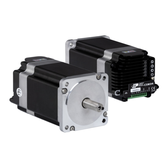
920-0160 Rev. A CSM34 Hardware Manual 02/28/2023 1 Introduction Thank you for selecting the Applied Motion Products CSM34 series motor. The CSM34 series motor is designed for space saving, easy control and long-lasting performance. 1.1 Features • Integrated Motor and Drive Package •... -
Page 4: Safety Instructions
920-0160 Rev. A CSM34 Hardware Manual 02/28/2023 1.2 Safety Instructions Only qualified personnel should transport, assemble, install, operate, or maintain this equipment. Properly qualified personnel are persons who are familiar with the transport, assembly, installation, operation, and maintenance of motors, and who meet the appropriate qualifications for their jobs. -
Page 5: Getting Started
920-0160 Rev. A CSM34 Hardware Manual 02/28/2023 2 Getting Started The following item is needed: A 12 - 70 Volt DC power supply. See the section below titled “Choosing a Power Supply” for help in choosing the right one. 2.1 Choosing a Power Supply The main considerations when choosing a power supply are the voltage and current requirements for the application. -
Page 6: Current & Torque Curve
920-0160 Rev. A CSM34 Hardware Manual 02/28/2023 2.1.2 Current & Torque Curve The maximum supply currents required by the CSM34 are shown in the charts below at different power supply voltage inputs. The CSM34 power supply current is lower than the winding currents because it uses switching amplifiers to convert a high voltage and low current into lower voltage and higher current. - Page 7 920-0160 Rev. A CSM34 Hardware Manual 02/28/2023 CSM34X3L-A 24V Cont Torq Peak Torq Full load Current No load Current 0.5 1 2 3 4 5 6 7 8 9 10 15 20 25 30 35 40 45 50 Speed (RPS) CSM34X3L-A 48V Cont Torq Peak Torq...
- Page 8 920-0160 Rev. A CSM34 Hardware Manual 02/28/2023 CSM34X5L-A 24V Cont Torq Peak Torq Full load Current No load Current 0.5 1 2 3 4 5 6 7 8 9 10 15 20 25 30 35 40 45 50 Speed (RPS) CSM34X5L-A 48V Cont Torq Peak Torq...
-
Page 9: Control Panel
920-0160 Rev. A CSM34 Hardware Manual 02/28/2023 2.2 Control Panel CSM has a LED display on the back side of the Motor. Enable status Mode Up Down Set 2.2.1 Menu Below are the operation of the CSM dip switch and status display. Default Display Press “... -
Page 10: Motion Simulation
920-0160 Rev. A CSM34 Hardware Manual 02/28/2023 2.2.2 Motion Simulation Motion Simulation Return to parameter selection Jog CCW Press and hold “ ” “ ” to change direction Release button to stop jog Speed is defined by PR001... -
Page 11: Input And Output
920-0160 Rev. A CSM34 Hardware Manual 02/28/2023 3 Input and Output CSM have the following Input and Output: • 4 optical isolated digital input, 5-24VDC • 2 optical isolated digital output max 30V/100 mA X COM Y COM 3.1 Input X1,X2,X3,X4 All 4 digital inputs for CSM are optical isolated. - Page 12 920-0160 Rev. A 920-0160 Rev. A CSM34 Hardware Manual CSM34 Hardware Manual 02/28/2023 02/28/2023 XCOM 12-24V Drive Switch or Relay Power (Close: Logic Low) Supply X1/X2/X3/X4 Connecting Input to Switch and Relay XCOM 12-24V Drive Power Output Supply – X1/X2/X3/X4 Output Connecting an NPN type Proximity Sensor to an Input (when prox sensor activates, input goes low)
- Page 13 920-0160 Rev. A CSM34 Hardware Manual 02/28/2023 3.2 Output Y1,Y2 Description Alarm Output Dynamic In Postion Y COM Output COM Wiring Diagram 12-24VDC Power – Y1/Y2 Load CSM34 YCOM Connecting Sinking Output 12-24VDC Power – Y1/Y2 CSM34 YCOM Connecting to sinking output with PLC 12-24VDC Power –...
-
Page 14: Drive Installation
CSM34 Hardware Manual 920-0160 Rev. A 02/28/2023 4 Drive Installation CSM34 must be mounted to provide maximum heat sinking and airflow. Keep enough space around the Integrated Motor to allow for airflow. • Never use the drive where there is no airflow or where other devices cause the surrounding air to be more than 40°C (104°F). -
Page 15: Reference
920-0160 Rev. A CSM34 Hardware Manual 02/28/2023 6 Reference 6.1 Dimension 69.6 1 : 1 0.03 14 0.012 M5 10Min 33 0.2 4 X 6.5 0.2 2 0.2 8.5 0.3 Model Length(mm) CSM34-3 CSM34-5 161.8 6.2 Specification Model CSM34X3L-A CSM34X5L-A Input Voltage DC 24-70VDC Max Torque... -
Page 16: Contacting Applied Motion Products
CSM34 Hardware Manual 7 Contacting Applied Motion Products Applied Motion Products, Inc. 18645 Madrone Pkwy, Morgan Hill, CA 95037 USA Web: applied-motion.com Phone: 1-800-525-1609 Email: support@applied-motion.com...
Need help?
Do you have a question about the Applied Motion Products CSM34 and is the answer not in the manual?
Questions and answers