
Related Manuals for Moons' RS03-S-A


Summary of Contents for Moons' RS03-S-A
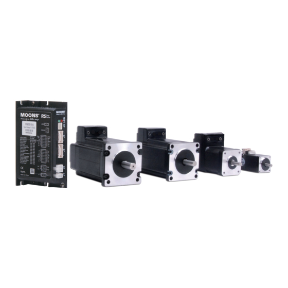
- Page 1 RS03/06-S/Q Step-Servo System Hardware Manual SHANGHAI AMP & MOONS’AUTOMATION CO.,LTD. 9 / 28 / 2015...
-
Page 2: Table Of Contents
RS03/06-S/Q Hardware Manual Contents 1. Introduction ..................4 1.1 Features ..................4 1.2 Block Diagram ................5 1.3 Safety Instructions ..............6 2. Getting Started ................7 2.1 Installing Software ..............7 2.2 Mounting the Hardware ............9 2.3 Choosing a Power Supply .............10 2.3.1 Voltage ..............10 2.3.2 Regeneration Clamp ..........10 2.3.3 Current ...............11 3. - Page 3 5.7 Drive Numbering System ............36 6. Optional Accessories (Sold separately)...........37 7. Contacting MOONS’ ..............41 This User Manual is only applicable to the following models. Communication Models RS-232 RS03-S-A RS06-S-A RS03-Q-A RS06-Q-A +86-400-820-9661 9 / 28 / 2015...
-
Page 4: Introduction
RS03/06-S/Q Hardware Manual 1. Introduction Thank you for selecting the MOONS’ RS series Step-Servo drive and motor. The Step-Servo is an innovative revolution for the world of stepper motor; it enhances the stepper motors with servo technology to create a product with exceptional feature and broad capability. 1.1 Features •... -
Page 5: Block Diagram
RS03/06-S/Q Hardware Manual 1.2 Block Diagram RS03/06-S/Q Block Diagram 24 - 70 VDC 5 Volt DC External Power Supply Power Supply RS-232 3.3VDC RS-232 RXD,+5V,TXD,GND Internal Voltage Logic Temp Supply Detect MOSFET X1/STEP+ motor X1/STEP- Power X2/DIR+ Amplifier X2/DIR- Optical Digital Software Filter... -
Page 6: Safety Instructions
RS03/06-S/Q Hardware Manual 1.3 Safety Instructions Only qualified personnel should transport, assemble, install, operate, or maintain this equipment. Properly qualified personnel are persons who are familiar with the transport, assembly, installation, operation, and maintenance of motors, and who meet the appropriate qualifications for their jobs. To minimize the risk of potential safety problems, all applicable local and national codes regulating the installation and operation of equipment should be followed. -
Page 7: Getting Started
RS03/06-S/Q Hardware Manual 2. Getting Started The following items are needed: • A 24-70 Volt DC power supply, see the section below entitled “Choose a Power Supply” for help in choosing the right one. • A compatible RS motor, please see the section below entitled “Recommended Motor” •... - Page 8 The software will recognize your drive, display the model and firmware version and it’s ready for action. The connectors and other points of interest are illustrated below: RS-232 Connector I/O Connector Encoder Connector Motor Connector Power Connector To Earth Ground Model RS03-S-A RS06-S-A RS03-Q-A RS06-Q-A +86-400-820-9661 9 / 28 / 2015...
-
Page 9: Mounting The Hardware
RS03/06-S/Q Hardware Manual 2.2 Mounting the Hardware Use the M3 or M4 screw to mount the RS series drive .The drive should be securely fastened to a smooth ,flat metal surface the will help conduct heat away from the chassis. If this is not possible, forced airflow from a fan maybe required to prevent the drive from overheating. -
Page 10: Choosing A Power Supply
RS03/06-S/Q Hardware Manual 2.3 Choosing a Power Supply The main considerations when choosing a power supply are the voltage and current requirements for the application. 2.3.1 Voltage The RS driver is designed to give optimum performance between 24 and 70 Volts DC. Choosing the voltage depends on the performance needed and motor/drive heating that is acceptable and/ or does not cause a drive over-temperature. -
Page 11: Current
RS03/06-S/Q Hardware Manual 2.3.3 Current The maximum supply currents required by the RS series step servo drive and motor are shown below in chats at different power supply voltage input. The RS drive power supply current is lower than the winding currents because it uses switching amplifiers to convert a high voltage and low current into low voltage and high current. - Page 12 RS03/06-S/Q Hardware Manual AM11RS3DMA 24V Power Torque Continuous Boost Supply Current Full Load No Load Speed(RPS) □ AM17RS1DM 24V Power Torque Continuous Boost Supply Current Full Load No Load Speed(RPS) □ AM17RS1DM 48V Power Torque Continuous Boost Supply Current Full Load No Load Speed(RPS) +86-400-820-9661...
- Page 13 RS03/06-S/Q Hardware Manual □ AM17RS2DM 24V Power Torque Continuous Boost Supply Current Full Load No Load Speed(RPS) □ AM17RS2DM 48V Power Torque Continuous Boost Supply Current Full Load No Load Speed(RPS) □ AM17RS3DM 24V Power Torque Continuous Boost Supply Current Full Load No Load Speed(RPS)
- Page 14 RS03/06-S/Q Hardware Manual □ AM17RS3DM 48V Power Torque Continuous Boost Supply Current Full Load No Load Speed(RPS) □ AM17RS4DM 24V Power Torque Continuous Boost Supply Current Full Load No Load Speed(RPS) □ AM17RS4DM 48V Power Torque Continuous Boost Supply Current Full Load No Load Speed(RPS)
- Page 15 RS03/06-S/Q Hardware Manual □ AM23RS2DM 24V Power Torque Continuous Boost Supply Current Full Load No Load Speed(RPS) □ AM23RS2DM 48V Power Torque Continuous Boost Supply Current Full Load No Load Speed(RPS) □ AM23RS2DM 70V Power Torque Continuous Boost Supply Current Full Load No Load Speed(RPS)
- Page 16 RS03/06-S/Q Hardware Manual □ AM23RS3DM 24V Power Torque Continuous Boost Supply Current Full Load No Load Speed(RPS) □ AM23RS3DM 48V Power Torque Continuous Boost Supply Current Full Load No Load Speed(RPS) □ AM23RS3DM 70V Power Torque Continuous Boost Supply Current Full Load No Load Speed(RPS)
- Page 17 RS03/06-S/Q Hardware Manual □ AM23RS4DM 24V Power Torque Continuous Boost Supply Current Full Load No Load Speed(RPS) □ AM23RS4DM 48V Power Torque Continuous Boost Supply Current Full Load No Load Speed(RPS) □ AM23RS4DM 70V Power Torque Continuous Boost Supply Current Full Load No Load Speed(RPS)
- Page 18 RS03/06-S/Q Hardware Manual □ AM24RS3DM 24V Power Torque Continuous Boost Supply Current Full Load No Load Speed(RPS) □ AM24RS3DM 48V Power Torque Continuous Boost Supply Current Full Load No Load Speed(RPS) □ AM24RS3DM 70V Power Torque Continuous Boost Supply Current Full Load No Load Speed(RPS)
-
Page 19: Installation/Connections
RS03/06-S/Q Hardware Manual 3. Installation/Connections 3.1 Connecting the Power Supply The RS series step servo drive and motor are shipped with a power cable, 2 meters long. Connect the red wire to the positive of the power supply. Connect the black wire to the negative of the power supply. -
Page 20: Connecting The Motor
RS03/06-S/Q Hardware Manual 3.2 Connecting the Motor The RS motors have two cables. One is the motor power cable, the other one is the encoder feedback cable. Plug the motor power cable into the motor connector on the drive and plug the encoder feedback cable into the encoder feedback connector on the drive. -
Page 21: Connecting To The Pc Using Rs-232
RS03/06-S/Q Hardware Manual 3.3 Connecting to the PC using RS-232 The RS series step servo drive and motor are shipped with a 1.5 meters RS-232 communication cable. The DB9 connector is used to connect to PC. The small end is a crimping connector used to connect to the drive. -
Page 22: Inputs And Outputs
RS03/06-S/Q Hardware Manual 3.4 Inputs and Outputs RS03/06-S/Q inputs and outputs include: • 4 optically isolated digital inputs, with adjustable bandwidth digital noise rejection filter, 5-24VDC • 3 optically isolated digital outputs, max 30V/100mA STEP- STEP+ DIR- DIR+ XCOM Shield I/O Connector Diagram +86-400-820-9661 9 / 28 / 2015... -
Page 23: Digital Inputs
RS03/06-S/Q Hardware Manual 3.4.1 Digital Inputs 3.4.1.1 X1/STEP/CW Limit and X2/DIR/CCW Limit High Speed Digital Inputs X1/STEP and X2/DIR are high-speed digital inputs operation 5-24V optical isolated differential signal, minimum pulse width 250ns, maximum pulse frequency 2MHz. • In Pulse and Direction mode, X1/STEP is pulse input and X2/DIR is direction signal input. •... - Page 24 RS03/06-S/Q Hardware Manual • In SCL mode, X1 can be configured as CW limit sensor input and X2 can be configured as CCW limit sensor input. NOTE: If current is flowing into or out of an input , the logic state of that input is low or closed. If no current is flowing, or the input is not connected, the logic state is high or open.
-
Page 25: X3/En, X4/Ar Digital Inputs
RS03/06-S/Q Hardware Manual 3.4.1.2 X3/EN, X4/AR Digital Inputs The X3/EN, X4/AR are digital inputs operation 5-24V optically isolated single-ended signal, sinking or souring, 5-24VDC, minimum pulse width 50μs, maximum pulse frequency 10KHz X3 can be configured as enable signal input to servo on or off the motor and X4 can be configured as alarm reset signal input to clear the alarm and turns to the normal status as servo off. -
Page 26: Digital Outputs
RS03/06-S/Q Hardware Manual 3.4.2 Digital Outputs 3.4.2.1 Y1/ALARM,Y2/IN POSITION,Y3/BRAKE Digital Outputs The Y1/alarm, Y2/In-position, Y3/brake are optically isolated digital outputs, single-ended, sinking or souring, max. 30VDC/100mA. • Y1 can be configured as alarm signal output. • Y2 can be configured as dynamic in position signal output (dynamic, checking in position all the time.) It also can be configured as Tach signal output, tach output produce pulses relative to the motor position with configurable resolution. -
Page 27: Troubleshooting
RS03/06-S/Q Hardware Manual 4. Troubleshooting 4.1 LED Error Codes The RS series step-servo package uses red and green LEDs to indicate status. When the motor is enabled, the green LED flashes slowly. When the green LED is solid, the motor is disabled. Errors are indicated by combinations of red and green flashes as shown below. -
Page 28: Reference Materials
RS03/06-S/Q Hardware Manual 5. Reference Materials 5.1 Drive Mechanical Outlines (Unit: mm) 4- R2.1 Model RS03-S-A RS03-Q-A RS06-S-A RS06-Q-A +86-400-820-9661 9 / 28 / 2015... -
Page 29: Technical Specifications
RS03/06-S/Q Hardware Manual 5.2 Technical Specifications Power Amplifier Amplifier Type Dual H-Bridge, 4 Quadrant Current Control 4 state PWM at 20 KHz RS03: Continuous Current 3A max, Boost Current 4.0A max (1.5s), current limitation auto set-up by attached motor Output Current RS06: Continuous Current 6A max, Boost Current 7.5A max (1.5s), current limitation auto set-up by attached motor External nominal 24 - 70 volt DC power supply required, Absolute maximum input voltage range... -
Page 30: Recommended Motor
RS03/06-S/Q Hardware Manual 5.3 Recommended Motor Motor Part Number Frame Size Holding Torque (N.m) Matching Drive AM11RS1DMA 0.065N•m AM11RS2DMA 0.08N•m AM11RS3DMA 0.125N•m RS03- ■ - A AM17RS1DM□ 0.3N•m AM17RS2DM□ 0.5N•m AM17RS3DM□ 0.6N•m AM17RS4DM□ 0.75N•m AM23RS2DM□ 0.9N•m AM23RS3DM□ 1.5N•m RS06- ■ - A AM23RS4DMA 2.5N•m AM24RS3DM□... -
Page 31: Motor Outlines
RS03/06-S/Q Hardware Manual 5.4 Motor Outlines AM11RS 16.2 4-M2.5 Depth 2.5 Min 23±0.1 φ22-0.052 4.5±0.1 φ5-0.012 Type(Unit: mm) Model AM11RS1DMA 43.8 AM11RS2DMA 52.9 AM11RS3DMA 64.1 AM17RS 42.3 4-M3 Depth 4.5Min φ22 Type(Unit: mm) Model φ6 AM17RS1DMA 59.5 φ5 AM17RS1DMB 59.5 φ6 AM17RS2DMA φ5... -
Page 32: Am23Rs
RS03/06-S/Q Hardware Manual AM23RS 56.3 4-φ5.1 47.14 φ38.1 Type(Unit: mm) Model φ8 AM23RS2DMA 77.5 φ6.35 AM23RS2DMB 5.85 77.5 φ8 AM23RS3DMA 99.5 φ6.35 AM23RS3DMB 5.85 99.5 φ8 AM23RS4DMA 102.5 +86-400-820-9661 9 / 28 / 2015... -
Page 33: Am24Rs
RS03/06-S/Q Hardware Manual AM24RS 47.14 4-φ4.5 φ38.1 Type(Unit: mm) Model φ10 AM24RS3DMA φ8 AM24RS3DMB +86-400-820-9661 9 / 28 / 2015... -
Page 34: Torque Curves
RS03/06-S/Q Hardware Manual 5.5 Torque Curves AM11RS Series Continuous AM11RS2DMA AM11RS1DMA Continuous Boost Boost Speed(rps) Speed(rps) Continuous AM11RS3DMA Boost Speed(rps) AM17RS Series □ □ Continuous AM17RS2DM Continuous AM17SS1DM Boost Boost Speed(rps) Speed(rps) □ Continuous Continuous AM17RS3DM AM17RS4DM □ Boost Boost Speed(rps) -
Page 35: Am23Rs Series
RS03/06-S/Q Hardware Manual AM23RS Series □ □ Continuous Continuous AM23RS2DM AM23RS3DM Boost Boost Speed(rps) Speed(rps) Continuous AM23RS4DM □ Boost Speed(rps) AM24RS Series □ Continuous AM24RS3DM Boost Speed(rps) +86-400-820-9661 9 / 28 / 2015... -
Page 36: Motor Numbering System
RS03/06-S/Q Hardware Manual 5.6 Motor Numbering System AM17 RS 1 D M A Mechanical Option A=Output shaft size Frame Size 11:φ5 11,17,23,24 17:φ6 Step Servo 23:φ8 24:φ10 Motor Size B=Output shaft size 1 = 1Stack 17:φ5 2 = 2Stack 23:φ6.35 D=DC Input 3 = 3Stack 24:φ8... -
Page 37: Optional Accessories (Sold Separately)
RS03/06-S/Q Hardware Manual 6. Optional Accessories (Sold separately) Catagory Technical Specification Switching Power Supply MF150A24AG-V 150W, 24V Switching Power Supply MF320A48AG-V 320W, 48V RC880 Regenaration Clamp 80VDC Max. 50W MS-USB-RS232-01 USB Converter USB-RS232 1108-□□□ Cable I/O Cable(for RS-S/Q drives) 2103-□□□ Cable Motor Extension Cable for AM17/23/24RS motor 2109-□□□... - Page 38 RS03/06-S/Q Hardware Manual Motor Extension Cable for AM17/23/24/34RS motor Housing:39-01-3049(Molex) Housing: 39-01-3048(Molex) Crimp:39-00-0040(Molex) Crimp: 39-00-0038(Molex) Length (L) Wiring Diagram 2103-100 PIN(J1) Colour(Signal) PIN(J2) 2103-300 Blue(B-) 2103-500 Red(B+) 2103-1000 Green(A-) Black(A+) Motor Extension Cable for AM11RS motor Housing:51065-0600(Molex) Housing: 39-01-3048(Molex) Crimp: 50212-8000(Molex) Crimp:...
- Page 39 RS03/06-S/Q Hardware Manual Encoder Extension Cable for AM17/23/24RS motor Housing:501646-1600(Molex) Housing:1-1903130-6(TYCO) Crimp:501648-1000(Molex) Crimp:1903120-1(TYCO) Length Wiring Diagram 2116-100 PIN(J1) Colour(Signal) PIN(J2) 2116-300 Blue(A+) 2116-500 Blue/Black(A-) 2116-1000 Green(B+) Green/Black(B-) Yellow(Z+) Yellow/Black(Z-) Red(+5V) Black(GND) Brown(U+) Brown/Black(U-) Gray(V+) Gray/Black(V-) White(W+) White/Black(W-) Shield +86-400-820-9661 9 / 28 / 2015...
- Page 40 RS03/06-S/Q Hardware Manual Encoder Extension Cable for AM11RS motor Housing:501646-1200(Molex) Housing:501646-1600(Molex) Crimp:501648-1000(Molex) Crimp:501648-1000(Molex) Length Wiring Diagram 2118-100 PIN(J1) Colour(Signal) PIN(J2) 2118-300 Blue(A+) 2118-500 Blue/Black(A-) 2118-1000 Green(B+) Green/Black(B-) Yellow(Z+) Yellow/Black(Z-) Red(+5V) Black(GND) Brown(U+) Brown/Black(U-) Gray(V+) Gray/Black(V-) White(W+) White/Black(W-) Shield I/O Cable(for RS-S/Q drives) Housing:501646-1400(Molex) Crimp:501648-1000(Molex) Fly leads...
-
Page 41: Contacting Moons
RS03/06-S/Q Hardware Manual 7. Contacting MOONS’ Service Center +86-400-820-9661 MOONS’Headquarters Ningbo Room 309, Tower B, Taifu Plaza, 565 Jiangjia Road, 168 Mingjia Road, Minhang District, Shanghai 201107, Jiangdong District, Ningbo, 315040, P.R. China P.R. China Tel: +86 (0)574 87052739 Tel: +86 (0)21 52634688 Fax:+86 (0)574 87052365 Fax:+86 (0)21 52634098 Guangzhou...
Need help?
Do you have a question about the RS03-S-A and is the answer not in the manual?
Questions and answers