
Related Manuals for Moons' SS-EC Series


Summary of Contents for Moons' SS-EC Series
- Page 1 SS-EC Step-Servo EtherCAT Drive Hardware Manual SS03-EC-D SS05-EC-D SS10-EC-D SHANGHAI AMP & MOONS’ AUTOMATION CO.,LTD. Rev. 1.0 06/21/2016...
-
Page 2: Table Of Contents
SS03/05/10-EC Hardware Manual Table of Contents 1 Introduction ...................... 4 1.1 Features ....................4 1.2 Block Diagram ..................5 1.3 Safety Instructions .................. 6 2 Getting Started ....................7 2.1 Installing the Software ................7 2.2 Mounting the Drive ................. 8 2.3 Connecting to the PC using mini USB ........... - Page 3 SS03/05/10-EC Hardware Manual 4.5 Function Control Mode ................38 4.5.1 Function Mode Description ............38 4.5.2 Operation Flow Chart .............. 39 4.6 Parameter Setting Mode ................ 40 4.6.1 Parameter Setting Description ..........40 4.6.2 Parameter Editing Examples ........... 41 4.6.3 Parameter list ................42 4.7 Control Panel Lock .................
-
Page 4: Introduction
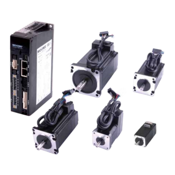
SS03/05/10-EC Hardware Manual 1 Introduction Thank you for selecting the MOONS’ SS-EC Step-Servo drive and motor. The SS-EC series combines servo technology with a stepper motor to create a product with exceptional features and broad capability. The SS-EC drive can operate as a standard EtherCAT slave using CANopen over EtherCAT (CoE). -
Page 5: Block Diagram
SS03/05/10-EC Hardware Manual 1.2 Block Diagram SS EtherCAT Block Diagram Power Supply Internal Filter Regen (24-70VDC) Clamp Auxiliary Power Internal DC Input Voltage (12-48VDC) Logic Power Temp. Supply Converter Det. High Speed Input Mosfet Digital Software Filter Optical Filter Isolation Power Amplifier Over... -
Page 6: Safety Instructions
SS03/05/10-EC Hardware Manual 1.3 Safety Instructions Only qualified personnel should transport, assemble, install, operate, or maintain this equipment. Properly qualified personnel are persons who are familiar with the transport, assembly, installation, operation, and maintenance of motors, and who meet the appropriate qualifications for their jobs. To minimize the risk of potential safety problems, all applicable local and national codes regulating the installation and operation of equipment should be followed. -
Page 7: Getting Started
SS03/05/10-EC Hardware Manual 2 Getting Started The following items are needed: • A 24-70 volt DC power supply, see Section 2.7 “Choosing a Power Supply” for help in choosing the right one. • An optional 12-48 volt DC power supply for Keep Alive function •... -
Page 8: Mounting The Drive
SS03/05/10-EC Hardware Manual 2.2 Mounting the Drive Use M4 screws to securely mount the SS-EC series drive to a smooth, flat metal surface that will help to conduct heat away from the chassis. If a heat conducting surface is not available, forced airflow from a fan may be required to prevent the drive from overheating. -
Page 9: Choosing The Right Com Port
SS03/05/10-EC Hardware Manual 2.4 Choosing the Right COM Port Open the “Device Manager” on the PC. There may or may not be a “Ports” selection. Connect the mini USB cable to the PC. The connected COM port should then be displayed. Choose this new COM(n) port in the Step-Servo Quick Tuner software. -
Page 10: Connecting The Auxiliary Power Supply
SS03/05/10-EC Hardware Manual 2.6 Connecting the Auxiliary Power Supply If the Keep Alive function is needed, an auxiliary power supply is required. Connect the auxiliary power supply “+” terminal to the drive terminal labeled “AUX”. Connect the auxiliary power supply “-” terminal to the drive terminal labeled “V-”. The SS-EC auxiliary Power Supply input accepts DC voltage range from 12 to 48VDC. - Page 11 SS03/05/10-EC Hardware Manual AM11SS1DMA 24V Power Torque Continuous Boost Supply Current Full Load No Load Speed(RPS) AM11SS2DMA 24V Power Torque Continuous Boost Supply Current Full Load No Load Speed(RPS) AM11SS3DMA 24V Power Torque Continuous Boost Supply Current Full Load No Load Speed(RPS) Rev.
- Page 12 SS03/05/10-EC Hardware Manual □ AM17SS1DG -N 24V Power Torque Continuous Boost Supply Current Full Load No Load Speed(RPS) □ AM17SS1DG -N 48V Power Torque Continuous Boost Supply Current Full Load No Load Speed(RPS) □ AM17SS2DG -N 24V Power Torque Continuous Boost Supply Current Full Load...
- Page 13 SS03/05/10-EC Hardware Manual □ AM17SS2DG -N 48V Power Torque Continuous Boost Supply Current Full Load No Load Speed(RPS) □ AM17SS3DG -N 24V Power Torque Continuous Boost Supply Current Full Load No Load Speed(RPS) □ AM17SS3DG -N 48V Power Torque Continuous Boost Supply Current Full Load...
- Page 14 SS03/05/10-EC Hardware Manual □ AM17SS4DG -N 24V Power Torque Continuous Boost Supply Current Full Load No Load Speed(RPS) □ AM17SS4DG -N 48V Power Torque Continuous Boost Supply Current Full Load No Load Speed(RPS) □ AM23SS2DG -N 24V Power Torque Continuous Boost Supply Current Full Load...
- Page 15 SS03/05/10-EC Hardware Manual □ AM23SS2DG -N 48V Power Torque Continuous Boost Supply Current Full Load No Load Speed(RPS) □ AM23SS2DG -N 70V Power Torque Continuous Boost Supply Current Full Load No Load Speed(RPS) □ AM23SS3DG -N 24V Power Torque Continuous Boost Supply Current Full Load...
- Page 16 SS03/05/10-EC Hardware Manual □ AM23SS3DG -N 48V Power Torque Continuous Boost Supply Current Full Load No Load Speed(RPS) □ AM23SS3DG -N 70V Power Torque Continuous Boost Supply Current Full Load No Load Speed(RPS) AM23SS4DGA-N 24V Power Torque Continuous Boost Supply Current Full Load No Load Speed(RPS)
- Page 17 SS03/05/10-EC Hardware Manual AM23SS4DGA-N 48V Power Torque Continuous Boost Supply Current Full Load No Load Speed(RPS) AM23SS4DGA-N 70V Power Torque Continuous Boost Supply Current Full Load No Load Speed(RPS) □ AM24SS3DG -N 24V Power Torque Continuous Boost Supply Current Full Load No Load Speed(RPS) Rev.
- Page 18 SS03/05/10-EC Hardware Manual □ AM24SS3DG -N 48V Power Torque Continuous Boost Supply Current Full Load No Load Speed(RPS) □ AM24SS3DG -N 70V Power Torque Continuous Boost Supply Current Full Load No Load Speed(RPS) AM34SS1DGA-N 24V Power Torque Continuous Boost Supply Current Full Load No Load Speed(RPS)
- Page 19 SS03/05/10-EC Hardware Manual AM34SS1DGA-N 48V Power Torque Continuous Boost Supply Current Full Load No Load Speed(RPS) AM34SS1DGA-N 70V Power Torque Continuous Boost Supply Current Full Load No Load Speed(RPS) AM34SS3DGA-N 24V Power Torque Continuous Boost Supply Current Full Load No Load Speed(RPS) Rev.
- Page 20 SS03/05/10-EC Hardware Manual AM34SS3DGA-N 48V Power Torque Continuous Boost Supply Current Full Load No Load Speed(RPS) AM34SS3DGA - N 70V Power Torque Continuous Boost Supply Current Full Load No Load Speed(RPS) AM34SS5DGA-N 24V Power Torque Continuous Boost Supply Current Full Load No Load Speed(RPS) Rev.
- Page 21 SS03/05/10-EC Hardware Manual AM34SS5DGA - N 48V Power Torque Continuous Boost Supply Current Full Load No Load Speed(RPS) AM34SS5DGA-N 70V Power Torque Continuous Boost Supply Current Full Load No Load Speed(RPS) Rev. 1.0 +86-400-820-9661 2016/7/30...
-
Page 22: Auxiliary Supply Voltage (Keep Alive Function)
SS03/05/10-EC Hardware Manual 2.7.3 Auxiliary Supply Voltage (Keep Alive Function) In addition to the main power supply input, the SS-EC also has an auxiliary power input (AUX power) for Keep Alive function of the drive. When the main power supply is off, the AUX power will keep the logic power on, allowing the drive to remember its state data (motor position, etc.). -
Page 23: Connecting The Motor
SS03/05/10-EC Hardware Manual 2.8 Connecting the Motor The SS motors have two cables - the motor power cable, and the encoder feedback cable. Use the optional motor extension cable and/or encoder extension cable, or make extension cables using connector housing and crimps included in package if more length is needed. Connect the motor power cable’s black, green, red and blue wires respectively to the drive’s A+, A-, B+ and B- connections. -
Page 24: Connecting The Ethercat
SS03/05/10-EC Hardware Manual 2.9 Connecting the EtherCAT Dual RJ-45 connectors (connection CN3) accept standard Ethernet cables and are categorized as 100BASE-TX (100 Mb/sec) ports. CAT5 or CAT5e (or higher) cables should be used. The IN port connects to a master, or to the OUT port of an upstream node. The OUT port connects to a downstream node. -
Page 25: Connecting The Sto
SS03/05/10-EC Hardware Manual 2.10 Connecting the STO On the SS EtherCAT step-servo drives, the STO (Safe Torque Off) function is connected via port CN4. The STO function shuts off the motor’s current turning off the motor output torque by forcibly turning off the signal of the drive’s power transistor. -
Page 26: Sto Signal Definition
SS03/05/10-EC Hardware Manual 2.10.4 STO Signal Definition Signal Symbol Description Control Mode SF1+ When SF1 has no input signal, e.g. the port is disconnected, SF1 will be Safety Input SF1 considered OFF. The upper half of the SF1- internal power transistor will be shut off. SF2+ Compatible with all When SF2 has no signal input, e.g. -
Page 27: Inputs And Outputs
SS03/05/10-EC Hardware Manual 3 Inputs and Outputs The SS-EC drive’s inputs and outputs include: • 8 optically isolated digital inputs, 5-24VDC high level voltage • 4 optically isolated digital outputs, max 30V/100mA sink or source current • 2 analog inputs, can be configured to 0-5V, 0-10V, ±5V or ±10V signal ranges. •... -
Page 28: Digital Inputs
SS03/05/10-EC Hardware Manual 3.1 Digital Inputs 3.1.1 X1, X2, X3 and X4 Digital Inputs X1, X2, X3 and X4: optically isolated, differential, 5-24VDC, minimum pulse width 250ns, maximum pulse frequency 2MHz • X1 can be used as general purpose input. •... -
Page 29: X5, X6, X7 And X8 Digital Inputs
SS03/05/10-EC Hardware Manual 3.1.2 X5, X6, X7 and X8 Digital Inputs X5, X6, X7 and X8: optically isolated, single-ended, 5-24VDC, minimum pulse width 50μs, maximum pulse frequency 10KHz • X5 can be used as servo on input or general purpose input. •... -
Page 30: Y1, Y2, Y3 And Y4 Digital Outputs
SS03/05/10-EC Hardware Manual 3.2 Y1, Y2, Y3 and Y4 Digital Outputs • Y1 can be used as an alarm signal output. It can also be used as a static in position signal output (static, checking in position when the motor is stopped), or as a dynamic in position signal output (dynamic, checking in position all the time). -
Page 31: Analog Inputs
Drive Y1/2/3/4- SS03/05/10-EC Hardware Manual Connecting a sinking output to a PLC’s input Power Supply – Y1/2/3/4+ SS-EC Drive Y1/2/3/4- Connecting a sourcing output to a PLC’s input 5-24 VDC relay Power Supply – Y1/2/3/4+ SS-EC Drive 1N4935 suppression diode Y1/2/3/4- Driving a relay 3.3 Analog Inputs... -
Page 32: Encoder Output
SS03/05/10-EC Hardware Manual 3.4 Encoder output The SS-EC drive has differential encoder outputs (AOUT+, AOUT-, BOUT+, BOUT-, ZOUT+, ZOUT-), with 26C31 line driver, 20 mA sink or source current max. These signals can be connected to the motion controller to provide feedback of the motor position. SS-EC Host Controller AOUT+... -
Page 33: Control Panel (Led Display And Keys)
SS03/05/10-EC Hardware Manual 4 Control Panel (LED display and keys) 4.1 Description of Control Panel LED Display Set Key Mode Key Up Key Down Key Symbol Name Details The LED display (5 digits, 7 segments) show the drive’s operating LED Display condition and warning codes, parameters and settings values. - Page 34 SS03/05/10-EC Hardware Manual Control mode switch flowchart: Power On In factory default mode, it will display motor’s rotatory velocity.(*NOTE 1) The last dot shows whether the drive is enable or disable. Monitor Status Press SET key back Press any key to Monitor Status Monitor Parameters Press the UP and...
-
Page 35: Led Display Description
SS03/05/10-EC Hardware Manual 4.3 LED display description 4.3.1 Decimal Point And Negative Sign Description LED display Description Negative sign: when the value to be displayed is a negative number ≥-9999,the highest digit will display as a negative sign. Decimal point: when the value to be displayed negative motor enable is a negative number ≤-10000, a decimal... -
Page 36: Jog Mode
SS03/05/10-EC Hardware Manual 4.3.5 Jog Mode LED display Description When the LED display reads “J--CW” it means the motor is rotating in a CW direction in JOG mode. When the LED display reads “J--CCW” it means the motor is rotating in a CCW direction in JOG mode 4.3.6 Control Panel Lock LED display Description... - Page 37 SS03/05/10-EC Hardware Manual N mode selection and setting LED display Description Unit n-00 Motor Rotation Speed n-01 Position Error counts n-02 Pulse Counter counts n-03 Encoder Counter counts n-04 Command Position Counter counts n-05 Drive Temperature x 0.1°C n-06 DC Bus Voltage x 0.1V n-07 SCL Address...
-
Page 38: Function Control Mode
SS03/05/10-EC Hardware Manual 4.5 Function Control Mode In function control mode (display reads: F+parameter number), you can select functions for preoperational mode, restart the drive, enable or disable the drive, etc. In status monitoring mode, press and hold for 1 second to enter function control mode. Press to select a to confirm or execute the function. -
Page 39: Operation Flow Chart
SS03/05/10-EC Hardware Manual 4.5.2 Operation Flow Chart status monitoring selection press and hold MODE key for 1 second press and hold SET key F-00 point to point mode function selection mode ,motor rotate press 1 rev in CW direction ,motor rotate press 1 rev in CCW direction press... -
Page 40: Parameter Setting Mode
SS03/05/10-EC Hardware Manual 4.6 Parameter Setting Mode 4.6.1 Parameter Setting Description The parameter setting mode (P+parameter number) allows you to select, display and edit the necessary parameter. In function control mode, press and hold for 1 second to enter parameter setting mode. Use to select the required parameter, and press to view or edit the parameter. -
Page 41: Parameter Editing Examples
SS03/05/10-EC Hardware Manual 4.6.2 Parameter Editing Examples Press mode to First digit flash Second digit flashing shift flashing digit Press Press Press Press Press up or down to increase or decrease value Press SET key to enter parameter editing mode Press mode to First digit Second digit flashing... -
Page 42: Parameter List
SS03/05/10-EC Hardware Manual 4.6.3 Parameter list Refer to the Host Command Reference for command details. Parameter Function SCL Command Number Display position loop proportional gain position loop differential gain differential filter velocity loop proportional gain velocity loop integrator gain reserved inertia feedforward gain overall filter step smoothing filter frequency command mode... - Page 43 SS03/05/10-EC Hardware Manual reserved reserved reserved reserved reserved reserved reserved encoder resolution reserved electronic gearing pulse mode setting position fault limit position limit for dynamic in position position limit for static in position in position timing pulse complete timing analog position gain analog velocity gain analog torque gain reserved...
- Page 44 SS03/05/10-EC Hardware Manual brake output motion output brake disengage delay brake engage delay filter input for X5 filter input for X6 filter input for X7 filter input for X8 reserved reserved immediate format protocol transmit delay baud rate reserved node id reserved parameter lock on control panel default display item of LEDs...
-
Page 45: Control Panel Lock
SS03/05/10-EC Hardware Manual 4.7 Control Panel Lock In order to prevent unauthorized or unintentional use of the key panel, a key panel lock is available on all SS-EC drives. When the lock feature is on, no function can be changed directly on drive’s control panel. - Page 46 SS03/05/10-EC Hardware Manual LED display Description Drive Over Temperature Internal Voltage Bad Over Voltage Highside Over Current Lowside Over Current Over Current Reading Bad Encoder Open Winding Position Limit Under Voltage CCW Limit and CW Limit CCW Limit CW Limit Current Foldback Communication Error Save Failed STO Activated Regen Failed Blank Q Segment Move while Disabled NOTE: Items in bold italic represent Drive Faults, which automatically disable the motor.
-
Page 47: Led Character Reference
SS03/05/10-EC Hardware Manual 4.9 LED Character Reference Rev. 1.0 +86-400-820-9661 2016/7/30... -
Page 48: Reference Materials
SS03/05/10-EC Hardware Manual 5 Reference Materials 5.1 Drive Mechanical Outlines 139.5 R2.5 Unit:mm Rev. 1.0 +86-400-820-9661 2016/7/30... -
Page 49: Drive Technical Specifications
SS03/05/10-EC Hardware Manual 5.2 Drive Technical Specifications Power Amplifier Amplifier Type Dual H-Bridge, 4 Quadrant Current Control 4 state PWM at 20 KHz SS03 Maximum continuous current 3A, boost current 4.5A (for 1.5s) Drive auto-sets the current limitation according to the attached motor SS05 Maximum continuous current 5A, boost current 7.5A (for 1.5s) Output Current Drive auto-sets the current limitation according to the attached motor... -
Page 50: Recommended Motors And Specifications
SS03/05/10-EC Hardware Manual 5.3 Recommended Motors and Specifications Permissible Shaft Load (N) Holding Rotor Encoder Max. Frame Mass Motor Part Matching Permissible Torque Inertia Resolution Speed Size Distance (L) from shaft end (mm) Number Drive Thrust Load G-cm counts/rev AM11SS1DMA 0.065 AM11SS2DMA SS03-EC-D... -
Page 51: Motor Mechanical Outlines
SS03/05/10-EC Hardware Manual 5.4 Motor Mechanical Outlines AM11SS unit: mm 4-M2.5 Depth 2.5 Min Model AM11SS1DMA 43.8 AM11SS2DMA 52.9 AM11SS3DMA 64.1 AM17SS-N unit: mm 42.3 4-M3 Depth 4.5Min φ22 Model φ6 AM17SS1DGA-N 59.5 φ5 AM17SS1DGB-N 59.5 φ6 AM17SS2DGA-N φ5 AM17SS2DGB-N φ6 AM17SS3DGA-N 73.5... - Page 52 SS03/05/10-EC Hardware Manual AM23SS-N 56.3 unit: mm 47.14 4-φ5.1 φ38.1 Model φ8 AM23SS2DGA-N 77.5 AM23SS2DGB-N φ6.35 5.85 77.5 φ8 AM23SS3DGA-N 99.5 AM23SS3DGB-N φ6.35 5.85 99.5 φ8 AM23SS4DGA-N 102.5 AM24SS-N unit: mm 47.14 4-φ4.5 φ38.1 Model φ10 AM24SS3DGA-N φ8 AM24SS3DGB-N 20.6 Rev.
- Page 53 SS03/05/10-EC Hardware Manual AM34SS-N unit: mm Model AM34SS1DGA-N AM34SS3DGA-N 117.5 AM34SS5DGA-N Rev. 1.0 +86-400-820-9661 2016/7/30...
-
Page 54: Torque Curves
SS03/05/10-EC Hardware Manual 5.5 Torque Curves Continuous Continuous AM11SS1DMA AM11SS2DMA Boost Boost Speed(rps) Speed(rps) Continuous AM11SS3DMA □ Continuous Boost AM17SS1DG -N Boost Speed(rps) Speed(rps) □ □ Continuous Continuous AM17SS2DG AM17SS3DG Boost Boost Speed(rps) Speed(rps) □ □ Continuous Continuous AM17SS4DG -N AM23SS2DG Boost Boost... - Page 55 SS03/05/10-EC Hardware Manual □ Continuous Continuous AM23SS3DG AM23SS4DGA -N Boost Boost Speed(rps) Speed(rps) Continuous □ Continuous AM34SS1DGA-N AM24SS3DG Boost Boost Speed(rps) Speed(rps) Continuous Continuous AM34SS5DGA-N AM34SS3DGA-N Boost Boost Speed(rps) Speed(rps) Rev. 1.0 +86-400-820-9661 2016/7/30...
-
Page 56: Motor Numbering System
SS03/05/10-EC Hardware Manual 5.6 Motor Numbering System AM17 SS 1 D G A-N Mechanical Option Frame Size 11, 17, 23, 24, 34 A = Output shaft size 11:φ5 Step Servo Encoder 17:φ6 G = 5000-Line 23:φ8 M = 1024-Line 24:φ10 Motor Size 34:φ14 1 = 1 stack... -
Page 57: Optional Accessories (Sold Separately)
SS03/05/10-EC Hardware Manual 6 Optional Accessories (Sold separately) 6.1 Cables Housing:501646-3200(Molex) ◇ I/O Cable Crimp:501648-1000(Molex) Length(L) 1117-200 Wiring Diagram PIN (J1) Color (Signal) PIN (J1) Color (Signal) Blue/White (X1+) Blue/Black (X1-) Green/White (X2+) Brown/White (Y1+) Green/Black (X2-) Brown/Black (Y1-) Red (X3+) Gray/White (Y2+) Orange (X3-) Gray/Black (Y2-) - Page 58 SS03/05/10-EC Hardware Manual ◇ Motor Extension Cable between SS-EC drive and AM17/23/24/34SS-N motor Housing:39-01-3049(Molex) Crimp:39-00-0040(Molex) Length(L) Wiring Diagram 1114-100 PIN(J1) Color (Signal) 1114-300 Blue(B-) Red(B+) 1114-500 1114-1000 Green(A-) Black(A+) ◇ Encoder Extension Cable between SS-EC drive and AM11SS Motor Housing:501646-1200(Molex) Housing:501646-1600(Molex) Crimp:501648-1000(Molex) Crimp:501648-1000(Molex)
-
Page 59: Mating Connectors
SS03/05/10-EC Hardware Manual ◇ USB Cable Length(L) 2620-150 1.5M ◇ Network Cable Common Shielded Length(L) Type Type 2012-030* 2013-030 0.3M 2012-300 2013-300 * 2012-030 is included in the drive package. 6.2 Mating Connectors Part Description Part Number Vendor Power Connector 5435970 Phoenix Contact... -
Page 60: Contacting Moons
SS03/05/10-EC Hardware Manual 7 Contacting MOONS’ MOONS’ Headquarters Ningbo Room 309, Tower B, Taifu Plaza, 565 Jiangjia Road, 168 Mingjia Road, Minhang District, Shanghai 201107, Jiangdong District, Ningbo, 315040, P.R. China P.R. China Tel: +86 (0)574 87052739 Tel: +86 (0)21 52634688 Fax:+86 (0)574 87052365 Fax:+86 (0)21 52634098 Guangzhou...
Need help?
Do you have a question about the SS-EC Series and is the answer not in the manual?
Questions and answers