
Related Manuals for Moons' Applied Motion Products SSDC-ECX-H


Summary of Contents for Moons' Applied Motion Products SSDC-ECX-H
- Page 1 SSDC-ECX-H Step-Servo System Hardware Manual SSDC06-ECX-H SSDC10-ECX-H 920-0163 Rev. A 12/4/2023...
-
Page 2: Table Of Contents
920-0163 Rev. A SSDC-ECX-H Hardware Manual 12/4/2023 1 Introduction ..............................3 1.1 Features ............................3 1.2 Safety Instructions .........................4 2 Getting Started ............................5 2.1 Installing Software ..........................6 2.2 Connecting the Power Supply ......................8 2.3 Choosing a Power Supply ......................9 2.3.1 Voltage ........................9 2.3.2 Current ........................10 2.4 Connecting the Motor ........................20 2.5 Connecting the EtherCAT ......................21... -
Page 3: Introduction
920-0163 Rev. A SSDC-ECX-H Hardware Manual 12/4/2023 1 Introduction Thank you for selecting the Applied Motion Products SSDC stepper drive. The SSDC-ECX model is a high performance EtherCAT control drive with a built-in motion controller capability. The SSDC-ECX drive can operate as a standard EtherCAT slave using CANopen over EtherCAT (CoE). It also supports Vendor specific profile over EtherCAT (VoE). -
Page 4: Safety Instructions
920-0163 Rev. A SSDC-ECX-H Hardware Manual 12/4/2023 1.2 Safety Instructions Only qualified personnel should transport, assemble, install, operate, or maintain this equipment. Properly qualified personnel are persons who are familiar with the transport, assembly, installation, operation, and maintenance of motors, and who meet the appropriate qualifications for their jobs. To minimize the risk of potential safety problems, all applicable local and national codes regulating the installation and operation of equipment should be followed. -
Page 5: Getting Started
920-0163 Rev. A SSDC-ECX-H Hardware Manual 12/4/2023 2 Getting Started The following items are needed: • A 24-70VDC power supply, see the section below entitled“Choose a Power Supply”for helping to choose the right one. • A compatible SS motor, please see the section below entitled “Recommended Motor” •... -
Page 6: Installing Software
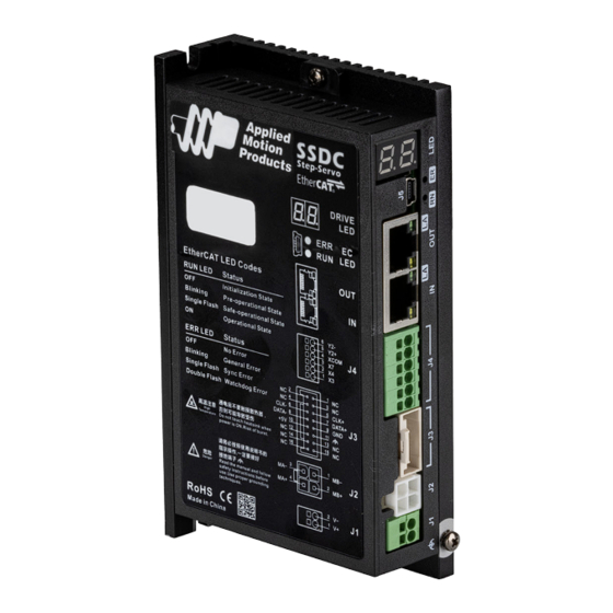
920-0163 Rev. A SSDC-ECX-H Hardware Manual 12/4/2023 2.1 Installing Software StepServo Quick Tuner is the PC based software application used to configure, and perform servo tuning, drive testing and evaluation of the step-servo products. System servo control gains, drive functionality and I/O configuration are set with StepServo Quick Tuner. It also contains an oscilloscope function to help set the servo control gains. - Page 7 920-0163 Rev. A SSDC-ECX-H Hardware Manual 12/4/2023 The connectors and other points of interest are illustrated below: SSED-ECX-H Communication Interface EtherCAT Output EtherCAT Input I/O Connector Encoder Connector Motor Connector Power Connector Ground Screws...
-
Page 8: Connecting The Power Supply
920-0163 Rev. A SSDC-ECX-H Hardware Manual 12/4/2023 2.2 Connecting the Power Supply Connect the V+ to the positive of the power supply. Connect the V- to the negative of the power supply. (NOTE: Be careful not to reverse the connection. Reversing the connection may open the internal fuse on the drive and void the warranty.) SSDC06: 24 –... -
Page 9: Choosing A Power Supply
920-0163 Rev. A SSDC-ECX-H Hardware Manual 12/4/2023 2.3 Choosing a Power Supply The main considerations when choosing a power supply are the voltage and current requirements for the application. 2.3.1 Voltage The SSDC drive is designed to give optimum performance between 24 and 48 Volts DC. Choosing the voltage depends on the performance needed and motor/drive heating that is acceptable and/or does not cause a drive over-temperature. -
Page 10: Current
920-0163 Rev. A SSDC-ECX-H Hardware Manual 12/4/2023 2.3.2 Current The maximum supply currents required by the SSDC series stepSERVO drive and motor are shown below in charts at different power supply voltage input. The SSDC drive power supply current is lower than the winding currents because it uses switching amplifiers to convert a high voltage and low current into low voltage and high current. - Page 11 920-0163 Rev. A SSDC-ECX-H Hardware Manual 12/4/2023 HT17-SS 1 DG_ 24V Power Torque Continuous Boost Supply Current Full Load No Load Speed(RPS) HT17-SS 1 DG_ 48V Power Torque Continuous Boost Supply Current Full Load No Load Speed(RPS) HT17-SS2DG_ 24V Power Torque Continuous Boost...
- Page 12 920-0163 Rev. A SSDC-ECX-H Hardware Manual 12/4/2023 HT17-SS2DG_ 48V Power Torque Continuous Boost Supply Current Full Load No Load Speed(RPS) HT17-SS 3 DG_ 24V Power Torque Continuous Boost Supply Current Full Load No Load Speed(RPS) HT17-SS3DG_ 48V Power Torque Continuous Boost Supply Current Full Load...
- Page 13 920-0163 Rev. A SSDC-ECX-H Hardware Manual 12/4/2023 HT17-SS 4 DG_ 24V Power Torque Continuous Boost Supply Current Full Load No Load Speed(RPS) HT17-SS4DG_ 48V Power Torque Continuous Boost Supply Current Full Load No Load Speed(RPS) HT23-SS2DG_ 24V Power Torque Continuous Boost Supply Current Full Load...
- Page 14 920-0163 Rev. A SSDC-ECX-H Hardware Manual 12/4/2023 HT23-SS3DG_ 48V Power Torque Continuous Boost Supply Current Full Load No Load Speed(RPS) HT23-SS3DG_ 70V Power Torque Continuous Boost Supply Current Full Load No Load Speed(RPS) HT23-SS4DG_ 24V Power Torque Continuous Boost Supply Current Full Load No Load Speed(RPS)
- Page 15 920-0163 Rev. A SSDC-ECX-H Hardware Manual 12/4/2023 HT23-SS4DG_ 48V Power Torque Continuous Boost Supply Current Full Load No Load Speed(RPS) HT23-SS4DG_ 70V Power Torque Continuous Boost Supply Current Full Load No Load Speed(RPS) HT24-SS3DG_ 24V Power Torque Continuous Boost Supply Current Full Load No Load Speed(RPS)
- Page 16 920-0163 Rev. A SSDC-ECX-H Hardware Manual 12/4/2023 HT24-SS3DG_ 48V Power Torque Continuous Boost Supply Current Full Load No Load Speed(RPS) HT24-SS3DG_ 70V Power Torque Continuous Boost Supply Current Full Load No Load Speed(RPS) HT34-SS1DG_ 24V Power Torque Continuous Boost Supply Current Full Load No Load Speed(RPS)
- Page 17 920-0163 Rev. A SSDC-ECX-H Hardware Manual 12/4/2023 HT34-SS1DG_ 48V Power Torque Continuous Boost Supply Current Full Load No Load Speed(RPS) HT34-SS1DG_ 70V Power Torque Continuous Boost Supply Current Full Load No Load Speed(RPS) HT34-SS3DG_ 24V Power Torque Continuous Boost Supply Current Full Load No Load Speed(RPS)
- Page 18 920-0163 Rev. A SSDC-ECX-H Hardware Manual 12/4/2023 HT34-SS3DG_ 48V Power Torque Continuous Boost Supply Current Full Load No Load Speed(RPS) HT34-SS3DG_ 70V Power Torque Continuous Boost Supply Current Full Load No Load Speed(RPS) HT34-SS5DG_ 24V Power Torque Continuous Boost Supply Current Full Load No Load Speed(RPS)
- Page 19 920-0163 Rev. A SSDC-ECX-H Hardware Manual 12/4/2023 HT34-SS5DG_ 48V Power Torque Continuous Boost Supply Current Full Load No Load Speed(RPS) HT34-SS5DG_ 70V Power Torque Continuous Boost Supply Current Full Load No Load Speed(RPS)
-
Page 20: Connecting The Motor
920-0163 Rev. A SSDC-ECX-H Hardware Manual 12/4/2023 2.4 Connecting the Motor The StepServo motors have two different cables. One is the motor power cable, the other one is the encoder feedback cable. Plug the motor power cable into the motor connector on the drive and plug the encoder feedback cable into the encoder feedback connector on the drive. -
Page 21: Connecting The Ethercat
920-0163 Rev. A SSDC-ECX-H Hardware Manual 12/4/2023 2.5 Connecting the EtherCAT Dual RJ-45 connectors accept standard Ethernet cables and are categorized as 100BASE-TX(100 Mb/sec) ports. CAT5 or CAT5e (or higher) cables should be used. The IN port connects to a master, or to the OUT port of an upstream node. -
Page 22: Inputs And Outputs
920-0163 Rev. A SSDC-ECX-H Hardware Manual 12/4/2023 3 Inputs and Outputs SSDC-ECX-H inputs and outputs include: • 3 Optically isolated digital inputs, 5 - 24VDC logic • 1 Optically isolated, Open Collector, 30V/100 mA max XCOM I/O Connector Diagram 3.1 Digital Inputs SSDC-ECX-H series drive has several digital optically isolated inputs, the function of every input can be configurated by StepServo Quick Tuner software. - Page 23 920-0163 Rev. A SSDC-ECX-H Hardware Manual 12/4/2023 X3, X4, X7: Optically isolated, 5-24VDC, Minimum pulse width = 100μs, Maximum pulse frequency = 5KHz. Because the input is an optically isolated circuit, a 5-24V power supply is needed. For example, you can use the power supply of the PLC when you are using a PLC control system, but if you want to connect a relay or mechanical switch to the input, you need a power supply.
-
Page 24: Digital Outputs
920-0163 Rev. A SSDC-ECX-H Hardware Manual 12/4/2023 3.2 Digital Outputs SSDC-ECX-H series drive has one digital differential output whose function can be configured via StepServo Quick Tuner. Signal Pin No. Function Available function: Release brake output Static in position output Dynamic in position output General purpose output... - Page 25 920-0163 Rev. A SSDC-ECX-H Hardware Manual 12/4/2023 Y2: Optically isolated, 5-24VDC, Maximum pulse frequency = 10KHz. The diagrams below show how to connect to the output: (NOTE: Do not connect the outputs to more than 30VDC power supply. And the current of each output terminal must not exceed 100mA.) 5 - 24V Power Supply –...
-
Page 26: Mounting The Drive
920-0163 Rev. A SSDC-ECX-H Hardware Manual 12/4/2023 4 Mounting the Drive Use the M3 or M4 screw to mount the SSDC series drive .The drive should be securely fastened to a smooth, flat metal surface to help conduct heat away from the chassis. If this is not possible, forced airflow from a fan maybe required to prevent the drive from overheating. - Page 27 920-0163 Rev. A SSDC-ECX-H Hardware Manual 12/4/2023 Alarm Codes When the drive has an alarm, the LED flashes with the period of 0.5s to display the current alarm information . LED1 shows the word “E”or “E.”, LED2 shows specific error or warning code. The specific alarm description is shown in the below table.
-
Page 28: Reference Materials
920-0163 Rev. A SSDC-ECX-H Hardware Manual 12/4/2023 6 Reference Materials 6.1 Drive Mechanical Outlines(Units: mm) SSDC06/10-ECX-H... -
Page 29: Technical Specifications
920-0163 Rev. A SSDC-ECX-H Hardware Manual 12/4/2023 6.2 Technical Specifications Power Amplifier Amplifier Type Dual H-Bridge, 4 Quadrant Current Control 4 state PWM at 16 KHz SSDC06: Continuous Current 6A max, Boost Current 7.5A max (1.5s), current limitation auto set-up by attached motor Output Current SSDC10: Continuous Current 10A max, Boost Current 15A max (1.5s), current limitation auto set-up by attached motor... -
Page 30: Recommended Motors
920-0163 Rev. A SSDC-ECX-H Hardware Manual 12/4/2023 6.3 Recommended Motors Permissible Shaft Load (N) Holding Rotor Encoder Max. Frame Permissible Mass Matching Distance (L) from shaft end Torque Inertia Resolution Speed Size Motor Part Number Thrust Drive (mm) Load G-cm counts/rev HT11-SS1DMA 0.065... -
Page 31: Motor Dimensions (Unit:mm)
920-0163 Rev. A SSDC-ECX-H Hardware Manual 12/4/2023 6.4 Motor Dimensions (Unit:mm) HT11-SS (Unit: mm) - Page 32 920-0163 Rev. A SSDC-ECX-H Hardware Manual 12/4/2023 HT17-SS (Unit: mm)
- Page 33 920-0163 Rev. A SSDC-ECX-H Hardware Manual 12/4/2023 HT23-SS (Unit: mm)
- Page 34 920-0163 Rev. A SSDC-ECX-H Hardware Manual 12/4/2023 HT24-SS (Unit: mm)
- Page 35 920-0163 Rev. A SSDC-ECX-H Hardware Manual 12/4/2023 HT34-SS (Unit: mm)
-
Page 36: Torque Curves
920-0163 Rev. A SSDC-ECX-H Hardware Manual 12/4/2023 6.5 Torque Curves Continuous HT11-SS1DM_ Continuous HT11-SS2DM_ Boost Boost 14.2 21.2 11.3 12.7 Speed(rps) Speed(rps) Continuous Continuous HT11-SS3DM_ HT17-SS1DG_ Boost Boost 28.3 56.6 22.7 42.5 28.3 14.2 Speed(rps) Speed(rps) Continuous Continuous HT17-SS2DG_ HT17-SS3DG_ Boost Boost... - Page 37 920-0163 Rev. A SSDC-ECX-H Hardware Manual 12/4/2023 Continuous Continuous HT23-SS4DG_ HT23-SS3DG_ Boost Boost 495.7 424.9 283.2 212.4 141.6 70.8 Speed(rps) Speed(rps) Continuous Continuous HT24-SS3DG_ HT34-SS1DG_ Boost Boost Speed(rps) Speed(rps) Continuous Continuous HT34-SS3DG_ HT34-SS5DG_ Boost Boost 1416 1133 Speed(rps) Speed(rps)
-
Page 38: Drive Numbering System
920-0163 Rev. A SSDC-ECX-H Hardware Manual 12/4/2023 6.6 Drive Numbering System SSDC 06 - ECX - H Step Servo I/O Connector Type H = 6 Pins Push-in Output Current Communication 06 = 6A ECX = New generation EtherCAT 10 = 10A... -
Page 39: Accessories
920-0163 Rev. A SSDC-ECX-H Hardware Manual 12/4/2023 7 Accessories 7.1 Standard Accessories (Included) • -EC Type Model Catagory Vendor Description Cable Power supply cable CAT5 Ethernet Cable 0.3m network cable Screwdriver / Screwdriver 39-01-3048 Housing Molex Motor connector housing J2 501646-1600 Housing Molex... -
Page 40: Extended Motor Cable( For Ssdc Drive And Ht11Ss Motor)
920-0163 Rev. A SSDC-ECX-H Hardware Manual 12/4/2023 7.2.2 Extended motor cable (For SSDC drive and HT11SS motor) Housing:51065-0600(Molex) Housing: 39-01-3048(Molex) Crimp:50212-8000(Molex) Crimp: 39-00-0038(Molex) Length(L) Wiring Diagram 3004-408-1M PIN(J1) Color (Signal) 3004-408-3M Blue(B-) 3004-408-5M Red(B+) 3004-408-10M Green(A-) Black(A+) 7.2.3 Extended motor cable (For SSDC drive and HT17/23/24/34SS motor) Housing:... -
Page 41: Extended Encoder Cable (For Ssdc Drive And Ht11 Motor)
920-0163 Rev. A SSDC-ECX-H Hardware Manual 12/4/2023 7.2.4 Extended encoder cable (For SSDC drive and HT11 motor) Housing:501646-1200(Molex) Housing: J21DF-16V-KX-L(JST) Crimp:501648-1000(Molex) Crimp: SJ2F-002GF-P1.0(JST) Length(L) Wiring Diagram 3004-339-1M PIN (J1) Color (Signal) PIN (J2) PIN (J1) Color (Signal) PIN (J2) 3004-339-3M Blue (A+) Shield 3004-339-5M... -
Page 42: Regeneration Clamp Rc880
920-0163 Rev. A SSDC-ECX-H Hardware Manual 12/4/2023 7.2.6 Regeneration Clamp RC880 When using a regulated power supply you may encounter a problem with regeneration. The regenerated energy is transferred back to the power supply. This can trip the overvoltage protection of a switching power supply, causing it to shut down. -
Page 43: Contacting Applied Motion Products
920-0163 Rev. A SSDC-ECX-H Hardware Manual 12/4/2023 8 Contacting Applied Motion Products Applied Motion Products, Inc. 18645 Madrone Pkwy, Morgan Hill, CA 95037 USA Web: applied-motion.com Phone: 800-525-1609 Email: support@applied-motion.com...
Need help?
Do you have a question about the Applied Motion Products SSDC-ECX-H and is the answer not in the manual?
Questions and answers