
Related Manuals for Moons' SS03-S-A


Summary of Contents for Moons' SS03-S-A
- Page 1 SS-S/Q/C Step-Servo Drive Hardware Manual SHANGHAI AMP & MOONS AUTOMATION CO.,LTD. Rev. 1.1 0004102014...
-
Page 2: Table Of Contents
SS03/05/10-S/Q/C Hardware Manual Contents 1 Introduction ................. 4 1.1 Features ....................4 1.2 Block Diagram ...................5 1.3 Safety Instructions ................7 2 Getting Started ................8 2.1 Installing Software ................8 2.2 Connecting to the PC using RS-232 ..........10 2.3 Connecting to a Host using RS-485 ..........10 2.3.1 RS-485 Four-wire Con guration ............ - Page 3 6.7 Drive Numbering System ..............41 7 Optional Accessories (Sold separately) ........42 8 Contacting MOONS ............... 44 This User Manual is only applicable to the following models. Communications Models RS-232 RS-485 CANopen SS03-S-A SS05-S-A SS10-S-A SS03-S-R SS05-S-R SS10-S-R SS03-Q-A SS05-Q-A SS10-Q-A SS03-Q-R...
-
Page 4: Introduction
SS03/05/10-S/Q/C Hardware Manual 1 Introduction Thank you for selecting the MOONS’ SS series Step-Servo drive and motor. SS series combines servo technology with an stepper motor to create a product with exceptional feature an broad capability. 1.1 Features Programmable, digital step-servo drive and motor package Operates from a 24 to 75 volt DC power supply Control modes: Torque Control... -
Page 5: Block Diagram
SS03/05/10-S/Q/C Hardware Manual 1.2 Block Diagram Rev. 1.1 400-820-9661 0004102014... - Page 6 SS03/05/10-S/Q/C Hardware Manual Rev. 1.1 400-820-9661 0004102014...
-
Page 7: Safety Instructions
SS03/05/10-S/Q/C Hardware Manual 1.3 Safety Instructions Only quali ed personnel should transport, assemble, install, operate, or maintain this equipment. Properly quali ed personnel are persons who are familiar with the transport, assembly, installation, operation, and maintenance of motors, and who meet the appropriate quali cations for their jobs. To minimize the risk of potential safety problems, all applicable local and national codes regulating the installation and operation of equipment should be followed. -
Page 8: Getting Started
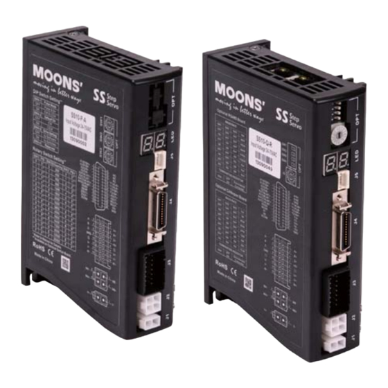
SS03/05/10-S/Q/C Hardware Manual 2 Getting Started The following items are needed: A 24-75 Volt DC power supply, see the section below entitled “Choose a Power Supply” for help in choosing the right one. A compatible SS motor, please see the section below entitled “Recommended Motor” A PC running Microsoft Windows XP/Vista/Windows7(Using serial communication port. - Page 9 SS03/05/10-S/Q/C Hardware Manual The connectors and other points of interest are illustrated below: RS-232 Connector I/O Connector Encoder Connector Motor Connector Ground Screw Power Connector Model SS03-S-A SS05-S-A SS10-S-A SS03-Q-A SS05-Q-A SS10-Q-A DIP Switch Rotary Switch LED Display RS-232 Connector...
-
Page 10: Connecting To The Pc Using Rs-232
SS03/05/10-S/Q/C Hardware Manual 2.2 Connecting to the PC using RS-232 The SS drives are shipped with a 1.5 meters RS-232 communication cable. The DB9 connector is used to connect to PC. The small end is a crimping connector used to connect to the drive. Located the SS drive within 1.5 meters of the PC. -
Page 11: Rs-485 Four-Wire Con Guration
SS03/05/10-S/Q/C Hardware Manual RS-485 four-wire system utilize separate transmit and receive wires. One pair of wires connect the host’s transmit signals(TX+/TX-) to each drive’s RX+/RX- receive terminals. The other pair connects the drive’s TX+/TX- terminals to the host’s receive signals. A logical ground terminal is provided on each drive and can be used to keep all the drives at the same ground potential. -
Page 12: Connecting The Power Supply
SS03/05/10-S/Q/C Hardware Manual 2.5 Connecting the Power Supply The SS drives are shipped with a power cable, 2 meters long. Connect the red wire to the positive of the power supply. Connect the black wire to the negative of the power supply. Plug the cable into the power connector of the drive. -
Page 13: Current
SS03/05/10-S/Q/C Hardware Manual 2.6.2 Current The maximum supply currents required by the SS series step servo drive and motor are shown below in chats at different power supply voltage input. The SS drive power supply current is lower low current into low voltage and high current. The more power supply voltage exceeds the motor voltage,the less current will be required from the power supply. - Page 14 SS03/05/10-S/Q/C Hardware Manual AM11SS3DMA 24V Power Torque Continuous Boost Supply Current Full Load No Load Speed(RPS) AM17SS1DG 24V Power Torque Continuous Boost Supply Current Full Load No Load Speed(RPS) AM17SS1DG 48V Power Torque Continuous Boost Supply Current Full Load No Load Speed(RPS) Rev.
- Page 15 SS03/05/10-S/Q/C Hardware Manual AM17SS2DG 24V Power Torque Continuous Boost Supply Current Full Load No Load Speed(RPS) AM17SS2DG 48V Power Torque Continuous Boost Supply Current Full Load No Load Speed(RPS) AM17SS3DG 24V Power Torque Continuous Boost Supply Current Full Load No Load Speed(RPS) Rev.
- Page 16 SS03/05/10-S/Q/C Hardware Manual AM17SS3DG 48V Power Torque Continuous Boost Supply Current Full Load No Load Speed(RPS) AM17SS4DG 24V Power Torque Continuous Boost Supply Current Full Load No Load Speed(RPS) AM17SS4DG 48V Power Torque Continuous Boost Supply Current Full Load No Load Speed(RPS) Rev.
- Page 17 SS03/05/10-S/Q/C Hardware Manual AM23SS2DG 24V Power Torque Continuous Boost Supply Current Full Load No Load Speed(RPS) AM23SS2DG 48V Power Torque Continuous Boost Supply Current Full Load No Load Speed(RPS) AM23SS2DG 70V Power Torque Continuous Boost Supply Current Full Load No Load Speed(RPS) Rev.
- Page 18 SS03/05/10-S/Q/C Hardware Manual AM23SS3DG 24V Power Torque Continuous Boost Supply Current Full Load No Load Speed(RPS) AM23SS3DG 48V Power Torque Continuous Boost Supply Current Full Load No Load Speed(RPS) AM23SS3DG 70V Power Torque Continuous Boost Supply Current Full Load No Load Speed(RPS) Rev.
- Page 19 SS03/05/10-S/Q/C Hardware Manual AM24SS3DG 24V Power Torque Continuous Boost Supply Current Full Load No Load Speed(RPS) AM24SS3DG 48V Power Torque Continuous Boost Supply Current Full Load No Load Speed(RPS) AM24SS3DG 70V Power Torque Continuous Boost Supply Current Full Load No Load Speed(RPS) Rev.
- Page 20 SS03/05/10-S/Q/C Hardware Manual AM34SS1DG 24V Power Torque Continuous Boost Supply Current Full Load No Load Speed(RPS) AM34SS1DG 48V Power Torque Continuous Boost Supply Current Full Load No Load Speed(RPS) AM34SS1DG 70V Power Torque Continuous Boost Supply Current Full Load No Load Speed(RPS) Rev.
- Page 21 SS03/05/10-S/Q/C Hardware Manual AM34SS3DG 24V Power Torque Continuous Boost Supply Current Full Load No Load Speed(RPS) AM34SS3DG 48V Power Torque Continuous Boost Supply Current Full Load No Load Speed(RPS) AM34SS3DG 70V Power Torque Continuous Boost Supply Current Full Load No Load Speed(RPS) Rev.
- Page 22 SS03/05/10-S/Q/C Hardware Manual AM34SS5DG 24V Power Torque Continuous Boost Supply Current Full Load No Load Speed(RPS) AM34SS5DG 48V Power Torque Continuous Boost Supply Current Full Load No Load Speed(RPS) AM34SS5DG 70V Power Torque Continuous Boost Supply Current Full Load No Load Speed(RPS) Rev.
-
Page 23: Connect To Motor
SS03/05/10-S/Q/C Hardware Manual 2.7 Connect to Motor The SS motors have two cables. One is the motor power cable, the other one is the encoder feedback cable. Plug the motor power cable into the motor connector on the drive and plug the encoder feedback cable into the encoder feed back connector on the drive. -
Page 24: Inputs And Outputs
SS03/05/10-S/Q/C Hardware Manual 3 Inputs and Outputs SS03/05/10-S/Q/C inputs and outputs include: 8 optically isolated digital inputs,5 - 24VDC logic 4 optically isolated digital outputs, maximum 30/100mA output I/O Connector Diagram Rev. 1.1 400-820-9661 0004102014... -
Page 25: Digital Inputs
SS03/05/10-S/Q/C Hardware Manual 3.1 Digital Inputs 3.1.1 X1/STEP and X2/DIR High Speed Digital Inputs X1/STEP and X2/DIR are high-speed digital inputs operation 5-24V optical isolated single-ended or differential signal. The maximum input frequency is 2MHz. In Pulse and Direction mode, X1/STEP is pulse input,and X2/DIR is direction signal input. In CW/CCW mode, X1/STEP is CW pulse input,and X2/DIR is CCW pulse input. -
Page 26: X3/Cw Limit And X4/Ccw Limit High-Speed Digital Inputs
SS03/05/10-S/Q/C Hardware Manual 3.1.2 X3/CW LIMIT and X4/CCW LIMIT High-speed Digital Inputs X3/CW LIMIT and X4/CCW LIMIT are high-speed digital inputs operation 5-24V optically isolated single-ended or differential signal. The maximum input frequency is 2MHz. input. NOTE:If current is owing into or out of an input ,the logic state of that input is low or closed. If no current is owing ,or the input is not connected,the logic state is high or open. -
Page 27: X5/En, X6/Ar,X7 And X8 Digital Inputs
SS03/05/10-S/Q/C Hardware Manual 3.1.3 X5/EN, X6/AR,X7 and X8 Digital Inputs The X5/EN, X6/AR,X7 and X8 are digital inputs operation 5-24V optically isolated single-ended signal. alarm reset signal input to clear the alarm and turns to the normal status as servo off. another one. -
Page 28: Digital Outputs
SS03/05/10-S/Q/C Hardware Manual 3.2 Digital Outputs 3.2.1 Y1/ALARM,Y2/IN POSITION,Y3 and Y4 Digital Outputs signal output(static, checking in position when motor is stopped) ,or as dynamic in position signal output (dynamic, checking in position all the time.) output(static, checking in position when motor is stopped) ,or as dynamic in position signal output (dynamic, checking in position all the time.),or as Timing signal output(50 pulses per rotation) position signal output(static, checking in position when motor is stopped) ,or as dynamic in... -
Page 29: Analog Inputs
SS03/05/10-S/Q/C Hardware Manual 3.3 Analog Inputs SS series drive has two analog signal inputs which can accept signal range of 0-5 Volts,0-10 volts proportional to the analog input. frequency. SS series provides a +5V/100mA limit power supply that can be used to power external devices such as potentiometer. -
Page 30: Mounting The Drive
SS03/05/10-S/Q/C Hardware Manual 4 Mounting the Drive Use the M3 or M4 screw to mount the SS series drive .The drive should be securely fastened to a more than 40 . Never put the drive where it can get wet or where metal or other electrically conductive particle particles can get on the circuity. -
Page 31: Alarm Error Code
SS03/05/10-S/Q/C Hardware Manual 5.2 Alarm Error Code The faults of drive are shown in bold italics . Motor will disable(Servo Off) when faults occur. Position Limit CCW Limit CW Limit Over Temperature Over Voltage Under Voltage Internal Voltage Over Current Current Foldback Open Winding Bad Encoder... -
Page 32: Assigning Rs-485 Address
SS03/05/10-S/Q/C Hardware Manual 5.3 Assigning RS-485 Address For the RS-485 drive,the dot point of LED2 indicates the communication address range is 0~15 when it is off. When the dot point of LED2 is on ,it indicates the communication address range is 16~31. -
Page 33: Rs-485 Baud Rate And Terminating Resistor
SS03/05/10-S/Q/C Hardware Manual 5.4 RS-485 Baud Rate and Terminating Resistor resistor (120 ohm) has already been installed inside of SS drive. To select/un-select the terminating resistor or communication baud rate setting can be selected by piano switch on SS drive: BAUD RATE 9600 19200... -
Page 34: Reference Materials
3600 4000 5000 6400 7200 8000 10000 20000 Refer to Manual for Details. Available on Optional Switch Board. RoHS Made in China Model SS03-S-A SS05-S-A SS10-S-A SS03-Q-A SS05-Q-A SS10-Q-A 94.5 Optional RS485 Board BAUD RATE BAUD RATE 9600 9600 19200 19200 Serial No. -
Page 35: Technical Speci Cations
SS03/05/10-S/Q/C Hardware Manual Dual H-Bridge, 4 Quadrant Current Control 4 state PWM at 20 KHz SS03 Maximum continuous current 3A, boost current 4.5A (for 1.5s) Drive auto-set the current limitation according to the attached motor SS05 Maximum continuous current 5A, boost current 7.5A (for 1.5s) Output Current Drive auto-set the current limitation according to the attached motor SS10 Maximum continuous current 10A, boost current 15A (for 1.5s) -
Page 36: Recommended Motor
SS03/05/10-S/Q/C Hardware Manual 6.3 Recommended Motor Holding Torque Motor Part Number Frame Size Matching Drive (N.m) AM11SS1DMA 0.05N·m AM11SS2DMA SS03- 0.07N·m AM11SS3DMA 0.09N·m AM17SS1DG 0.3N·m AM17SS2DG 0.5N·m AM17SS3DG 0.6N·m SS05- AM17SS4DG 0.75N·m AM23SS2DG 0.9N·m AM23SS3DG 1.5N·m AM24SS3DG 2.5N·m AM34SS1DGA 3.5N·m SS10- AM34SS3DGA 6.0N·m... -
Page 37: Motor Outlines
SS03/05/10-S/Q/C Hardware Manual 6.4 Motor Outlines AM11SS 16.2 4-M2.5 Depth 2.5 Min Motor Type 23±0.1 AM11SS1DMA 43.8 AM11SS2DMA 52.9 AM11SS3DMA 64.1 22-0.052 4.5±0.1 5-0.012 AM17SS 42.3 4-M3 Depth 4.5Min Type(Unit: mm) Motor Type AM17SS1DGA 59.5 AM17SS1DGB 59.5 AM17SS2DGA AM17SS2DGB AM17SS3DGA 73.5 AM17SS3DGB 73.5... - Page 38 SS03/05/10-S/Q/C Hardware Manual AM24SS 47.14 4-V4.5 V38.1 Type(Unit: mm) Motor Type AM24SS3DGA AM24SS3DGB AM34SS 69.6 4-6.5 V73.025 Type(Unit: mm) Motor Type AM34SS1DGA AM34SS3DGA 117.5 AM34SS5DGA Rev. 1.1 400-820-9661 0004102014...
-
Page 39: Torque Curves
SS03/05/10-S/Q/C Hardware Manual 6.5 Torque Curves Continuous Continuous AM11SS1DMA AM11SS2DMA Boost Boost Speed(rps) Speed(rps) Continuous AM11SS3DMA Boost Speed(rps) Continuous Continuous AM17SS1DG AM17SS2DG Boost Boost Speed(rps) Speed(rps) Continuous Continuous AM17SS3DG AM17SS4DG Boost Boost Speed(rps) Speed(rps) Rev. 1.1 400-820-9661 0004102014... - Page 40 SS03/05/10-S/Q/C Hardware Manual Continuous Continuous AM23SS2DG AM23SS3DG Boost Boost Speed(rps) Speed(rps) Continuous AM24SS3DG Boost Speed(rps) Continuous Continuous AM34SS3DGA AM34SS1DGA Boost Boost Speed(rps) Speed(rps) Continuous AM34SS5DGA Boost Speed(rps) Rev. 1.1 400-820-9661 0004102014...
-
Page 41: Motor Numbering System
SS03/05/10-S/Q/C Hardware Manual 6.6 Motor Numbering System AM11 SS 1 D G A Frame Size 11,17,23,24,34 A=Output shaft size 11: 5 17: 6 Step Servo 23: 8 24: 10 Motor Size 34: 14 1 = 1Stack B=Output shaft size 2 = 2Stack 17: 5 3 = 3Stack 23: 6.35... -
Page 42: Optional Accessories (Sold Separately)
SS03/05/10-S/Q/C Hardware Manual 7 Optional Accessories (Sold separately) Catagory Technical Specification Switching Power Supply MF150A24AG-V 150W, 24V Switching Power Supply MF320A48AG-V 320W, 48V Cable Motor Extension Cable for AM17/23/24/34SS motor 2103- Cable Motor Extension Cable for AM11SS motor 2109- Cable Encoder Extension Cable for AM17/23/24/34SS motor 2104- Cable... - Page 43 SS03/05/10-S/Q/C Hardware Manual Encoder Extension Cable for AM17/23/24/34SS motor Housing:J21DPM-16V-KX(JST) Housing:J2DF-16V-KX-L(JST) Wire protect cover: J21PF-16SCA(JST) Crimp:SJ2M-002GF-M1.0N(JST) Crimp:SJ2F-002GF-P1.0(JST) Wire protect cover: J21PF-16SCB(JST) Length Wiring Diagram 2104-100 PIN J1 Colour(Signal) PIN J2 2104-300 Blue A+ 2104-500 Blue/Black A- 2104-1000 Green B+ Green/Black B- Yellow Z+ Yellow/Black Z- Red +5V...
-
Page 44: Contacting Moons
SS03/05/10-S/Q/C Hardware Manual 8 Contacting MOONS Service Center +86-400-820-9661 Headquarters No. 168 Mingjia Road Industrial Park North Minhang District Shanghai 201107, P.R. China Tel: +86(0)21-52634688 Fax: +86(0)21-62968682 E-mail: info@moons.com.cn MOONS' Industries (America), Inc. 1113 North Prospect Avenue,Itasca, IL 60143 U.S.A. Tel: 001-630-833-5940 Fax: 001-630-833-5946 MOONS' Industries (Europe) S.r.l.
Need help?
Do you have a question about the SS03-S-A and is the answer not in the manual?
Questions and answers