
Subscribe to Our Youtube Channel
Related Manuals for Moons' SSDC Series


Summary of Contents for Moons' SSDC Series
- Page 1 SSDC-ECX-H/J Step-Servo System Hardware Manual SSDC06-ECX-H/J SSDC10-ECX-H/J SHANGHAI AMP&MOONS’ AUTOMATION CO.,LTD. Rev. 1.2 20/03/2020...
-
Page 2: Table Of Contents
SSDC-ECX-H/J Hardware Manual Contents 1 Introduction ........................3 1.1 Features ......................3 1.2 Block Diagram ....................4 1.3 Safety Instructions .....................5 2 Getting Started ......................6 2.1 Installing Software .....................7 2.3 Connecting the Power Supply ................9 2.4 Choosing a Power Supply .................10 2.4.1 Voltage .....................10 2.4.2 Current ....................11 2.5 Connecting the Motor ..................21 2.6 Connecting the EtherCAT ..................22... -
Page 3: Introduction
SSDC-ECX-H/J Hardware Manual 1 Introduction Thank you for selecting the MOONS’ SSDC series step-servo drive and motor. The SSDC-EC series are high performance EtherCAT fieldbus control step-servo drive which also integrates with built-in motion controller. The SSDC-EC drive can operate as a standard EtherCAT slave using CANopen over EtherCAT (CoE). -
Page 4: Block Diagram
SSDC-ECX-H/J Hardware Manual 1.2 Block Diagram SSDC-ECX-H/J EtherCAT Block Diagram Power Supply: Filter SSDC06/10: 24-70VDC Internal DC Input Voltage Logic Power Temp. Supply Converter Det. Mosfet Operational ANALOG Amplifter Power Amplifier Over Current Det. Single Ended Software Input Filter Ioslation Motor XCOM Single... -
Page 5: Safety Instructions
SSDC-ECX-H/J Hardware Manual 1.3 Safety Instructions Only qualified personnel should transport, assemble, install, operate, or maintain this equipment. Properly qualified personnel are persons who are familiar with the transport, assembly, installation, operation, and maintenance of motors, and who meet the appropriate qualifications for their jobs. To minimize the risk of potential safety problems, all applicable local and national codes regulating the installation and operation of equipment should be followed. -
Page 6: Getting Started
SSDC-ECX-H/J Hardware Manual 2 Getting Started The following items are needed: • A 24-70VDC power supply, see the section below entitled “Choose a Power Supply” for helping to choose the right one. • A compatible SS or RS motor, please see the section below entitled “Recommended Motor” •... -
Page 7: Installing Software
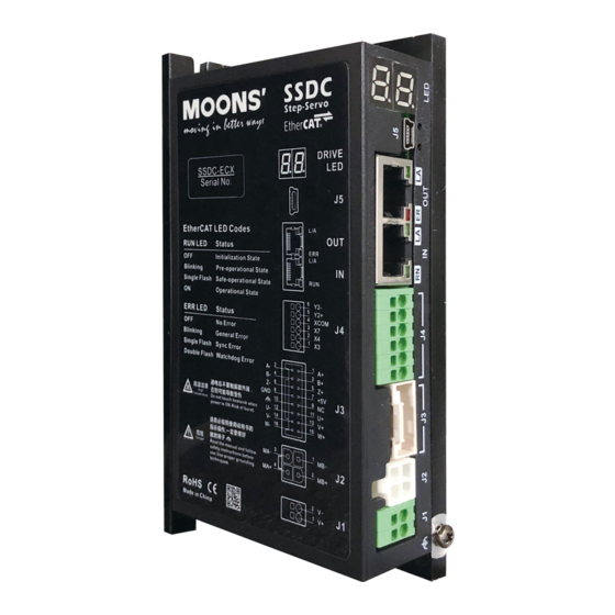
SSDC-ECX-H/J Hardware Manual 2.1 Installing Software Stepper Suite is the PC based software application used to configure, and perform servo tuning, drive testing and evaluation of the step-servo products. System servo control gains, drive functionality and I/O configuration are set with Stepper Suite. It also contains an oscilloscope function to help set the servo control gains. - Page 8 SSDC-ECX-H/J Hardware Manual The connectors and other points of interest are illustrated below: SSED-ECX-H SSED-ECX-J Communication Interface EtherCAT Output EtherCAT Input I/O Connector Encoder Connector Motor Connector Power Connector Ground Screws 2.2 Connecting to the PC using USB Connector J5 is USB communication port, please use the USB Mini-B cable to connect the drive and PC.
-
Page 9: Connecting The Power Supply
2.3 Connecting the Power Supply The SSDC series step-servo drive and motor are shipped with a power cable, 2 meters long. Connect the red wire to the positive of the power supply. Connect the black wire to the negative of the power supply. -
Page 10: Choosing A Power Supply
SSDC-ECX-H/J Hardware Manual 2.4 Choosing a Power Supply The main considerations when choosing a power supply are the voltage and current requirements for the application. 2.4.1 Voltage The SSDC drive is designed to give optimum performance between 24 and 48 Volts DC. Choosing the voltage depends on the performance needed and motor/drive heating that is acceptable and/or does not cause a drive over-temperature. -
Page 11: Current
SSDC-ECX-H/J Hardware Manual 2.4.2 Current The maximum supply currents required by the SSDC series step servo drive and motor are shown below in chats at different power supply voltage input. The SSDC drive power supply current is lower than the winding currents because it uses switching amplifiers to convert a high voltage and low current into low voltage and high current. - Page 12 SSDC-ECX-H/J Hardware Manual AM11RS3DMA 24V Power Torque Continuous Boost Supply Current Full Load No Load Speed (rps) □ □ AM17SS1DG -N AM17RS1DM 24V Power Torque Continuous Boost Supply Current Full Load No Load Speed (rps) □ □ AM17SS1DG AM17RS1DM 48V Power Torque Continuous Boost...
- Page 13 SSDC-ECX-H/J Hardware Manual □ □ AM17SS2DG -N AM17RS2DM 24V Power Torque Continuous Boost Supply Current Full Load Full Load Speed (rps) □ □ AM17SS2DG -N AM17RS2DM 48V Power Torque Continuous Boost Supply Current Full Load Full Load Speed (rps) □ □...
- Page 14 SSDC-ECX-H/J Hardware Manual □ □ AM17SS3DG -N AM17RS3DM 48V Power Torque Continuous Boost Supply Current Full Load Full Load Speed (rps) □ □ AM17SS4DG -N AM17RS4DM 24V Power Torque Continuous Boost Supply Current Full Load Full Load Speed (rps) □ □...
- Page 15 SSDC-ECX-H/J Hardware Manual □ □ AM23SS2DG -N AM23RS2DM 24V Power Torque Continuous Boost Supply Current Full Load Full Load Speed (rps) □ □ AM23SS2DG -N AM23RS2DM 48V Power Torque Continuous Boost Supply Current Full Load Full Load Speed (rps) □ □...
- Page 16 SSDC-ECX-H/J Hardware Manual □ □ AM23SS3DG -N AM23RS3DM 24V Power Torque Continuous Boost Supply Current Full Load Full Load Speed (rps) □ □ AM23SS3DG -N AM23RS3DM 48V Power Torque Continuous Boost Supply Current Full Load Full Load Speed (rps) □ □...
- Page 17 SSDC-ECX-H/J Hardware Manual □ □ AM24SS3DG -N AM24RS3DM 24V Power Torque Continuous Boost Supply Current Full Load Full Load Speed (rps) □ □ AM24SS3DG -N AM24RS3DM 48V Power Torque Continuous Boost Supply Current Full Load Full Load Speed (rps) □ □...
- Page 18 SSDC-ECX-H/J Hardware Manual AM34SS1DGA-N AM34RS1DMA 24V Power Torque Continuous Boost Supply Current Full Load Full Load Speed (rps) AM34SS1DGA-N AM34RS1DMA 48V Power Torque Continuous Boost Supply Current Full Load Full Load Speed (rps) AM34SS1DGA-N AM34RS1DMA 70V Power Torque Continuous Boost Supply Current Full Load Full Load...
- Page 19 SSDC-ECX-H/J Hardware Manual AM34SS3DGA-N AM34RS3DMA 24V Power Torque Continuous Boost Supply Current Full Load Full Load Speed (rps) AM34SS3DGA-N AM34RS3DMA 48V Power Torque Continuous Boost Supply Current Full Load Full Load Speed (rps) AM34SS3DGA-N AM34RS3DMA 70V Power Torque Continuous Boost Supply Current Full Load Full Load...
- Page 20 SSDC-ECX-H/J Hardware Manual AM34SS5DGA-N AM34RS5DMA 24V Power Torque Continuous Boost Supply Current Full Load Full Load Speed (rps) AM34SS5DGA-N AM34RS5DMA 48V Power Torque Continuous Boost Supply Current Full Load Full Load Speed (rps) AM34RS5DMA AM34SS5DGA-N 70V Power Torque Continuous Boost Supply Current Full Load Full Load...
-
Page 21: Connecting The Motor
SSDC-ECX-H/J Hardware Manual 2.5 Connecting the Motor The SS/RS motors have two different cables. One is the motor power cable, the other one is the encoder feedback cable. Plug the motor power cable into the motor connector on the drive and plug the encoder feedback cable into the encoder feedback connector on the drive. -
Page 22: Connecting The Ethercat
SSDC-ECX-H/J Hardware Manual 2.6 Connecting the EtherCAT Dual RJ-45 connectors accept standard Ethernet cables and are categorized as 100BASE-TX(100 Mb/sec) ports. CAT5 or CAT5e (or higher) cables should be used. The IN port connects to a master, or to the OUT port of an upstream node. The OUT port connects to a downstream node. If the drive is the last node on a network, only the IN port is used. -
Page 23: Inputs And Outputs
SSDC-ECX-H/J Hardware Manual 3 Inputs and Outputs SSDC-ECX-H inputs and outputs include: • 3 Optically isolated digital inputs, 5 - 24VDC logic • 1 Optically isolated, Open Collector, 30V/100 mA max XCOM I/O Connector Diagram SSDC-ECX-J inputs and outputs include: •... -
Page 24: Digital Inputs
SSDC-ECX-H/J Hardware Manual 3.1 Digital Inputs SSDC-ECX-H//J series drive has several digital optically isolated inputs, the function of every input can be configurated by Stepper Suite software. SSDC06/10-ECX-H Signal Pin No. Function Available function: CW limit sensor input Homing sensor input General purpose Available function:... - Page 25 SSDC-ECX-H/J Hardware Manual The diagrams below show how to connect the X3, X4 , X5, X7 and X8 to various commonly used devices. XCOM 5 - 24V SSDC Power Supply Switch or Relay (Closed: logic low) X3/X4/X5/X7/X8 Connecting a switch or relay to an input XCOM 5 - 24V SSDC...
-
Page 26: Digital Outputs
SSDC-ECX-H/J Hardware Manual 3.2 Digital Outputs SSDC-ECX-H//J series drive has several digital optically isolated outputs, the function of every output can be configurated by Stepper Suite software. SSDC06/10-ECX-H Signal Pin No. Function Available function: Release brake output Static in position output Dynamic in position output General purpose output SSDC06/10-ECX-J... - Page 27 SSDC-ECX-H/J Hardware Manual 5 - 24V Power Supply – Load Y2+/Y1/Y2 SSDC Y2-/YCOM Connecting a sourcing output to load 5 - 24V Power Supply – Y2+/Y1/Y2 SSDC Y2-/YCOM Connecting a sinking output to PLC's input 5 - 24V Power Supply –...
-
Page 28: Analog Inputs
SSDC-ECX-H/J Hardware Manual 3.3 Analog Inputs SSDC-ECX-J series drive has one analog signal inputs which can accept signal range of 0-5V, 0-10V,±5V and ±10V. Use the Stepper Suite to configure the input range, offset, deadband and noisy filter frequency. SSDC-ECX-J series provides a +5V/100mA limit power supply that can be used to power external devices such as potentiometer. -
Page 29: Mounting The Drive
4 Mounting the Drive Use the M3 or M4 screw to mount the SSDC series drive .The drive should be securely fastened to a smooth, flat metal surface will help conduct heat away from the chassis. If this is not possible, forced airflow from a fan maybe required to prevent the drive from overheating. - Page 30 SSDC-ECX-H/J Hardware Manual Alarm Codes When the drive has alarm, the LED flashes with the period of 0.5s to display the current alarm information . LED1 shows the word “E”or “E.”, LED2 shows specific error or warning code. The specific alarm description is shown in the below table.
-
Page 31: Reference Materials
SSDC-ECX-H/J Hardware Manual 6 Reference Materials 6.1 Drive Mechanical Outlines(Units: mm) SSDC06/10-ECX-H SSDC06/10-ECX-J Rev. 1.0 400-820-9661 20/07/2020... -
Page 32: Technical Specifications
SSDC-ECX-H/J Hardware Manual 6.2 Technical Specifications Power Amplifier Amplifier Type Dual H-Bridge, 4 Quadrant Current Control 4 state PWM at 20 KHz SSDC06: Continuous Current 6A max, Boost Current 7.5A max (1.5s), current limitation auto set-up by attached motor Output Current SSDC10: Continuous Current 10A max, Boost Current 15A max (1.5s), current limitation auto set-up by attached motor SSDC06:... -
Page 33: Recommended Motors
SSDC-ECX-H/J Hardware Manual 6.3 Recommended Motors Permissible Overhung Load(N) Rotor Encoder Maximum Frame Permissible Torque Mass Drive Inertia Resolution Speed Size Model Distance(L) from Shaft End(mm) Thrust Load counts/rev AM11RS1DMA 0.065 AM11RS2DMA 0.08 AM11RS3DMA 0.125 AM17RS1DM□ 0.26 4096 AM17RS2DM□ 0.42 AM17RS3DM□... -
Page 34: Motor Dimensions (Unit:mm)
SSDC-ECX-H/J Hardware Manual 6.4 Motor Dimensions (Unit:mm) AM11 Series 16.2 4-M2.5 Depth 2.5 Min 23±0.1 Model AM11RS1DMA 43.8 AM11RS2DMA 52.9 φ22-0.052 4.5±0.1 φ5-0.012 AM11RS3DMA 64.1 AM17 Series 42.3 4-M3 Depth 4.5Min Model Connector On Cable AM17RS1DMA 59.5 φ6 Motor cable AM17RS1DMB 59.5 φ5... - Page 35 SSDC-ECX-H/J Hardware Manual AM23 Series 56.3 47.14 4-V5.1 V38.1 Model Connector On Cable Motor cable AM23RS2DMA 77.5 φ8 Housing: 39-01-3048 (Molex),1pcs AM23RS2DMB 5.85 77.5 φ6.35 Crimp: 39-00-0038 (Molex),4pcs AM23RS3DMA 99.5 φ8 Encoder cable AM23RS3DMB 5.85 99.5 φ6.35 Housing: 1-1827864-6 (Tyco),1pcs AM23RS4DMA 102.5 φ8...
- Page 36 SSDC-ECX-H/J Hardware Manual AM24 Series 47.14 4-V4.5 V38.1 Model Connector On Cable Motor cable Housing: 39-01-3048 (Molex),1pcs AM24RS3DMA φ10 Crimp: 39-00-0038 (Molex),4pcs Encoder cable AM24RS3DMB 20.6 φ8 Housing: 1-1827864-6 (Tyco),1pcs Crimp: 1827569-2 (Tyco),11pcs Motor cable Housing: 39-01-3048 (Molex),1pcs AM24SS3DGA-N φ10 Crimp: 39-00-0038 (Molex),4pcs Encoder cable AM24SS3DGB-N...
- Page 37 SSDC-ECX-H/J Hardware Manual AM34 Series 69.6 4-Φ6.5 Φ73.025 Model Connector On Cable Motor cable AM34RS1DMA Housing: 39-01-3048 (Molex),1pcs Crimp: 39-00-0038 (Molex),4pcs AM34RS3DMA 117.5 Encoder cable Housing: 1-1827864-6 (Tyco),1pcs AM34RS5DMA Crimp: 1827569-2 (Tyco),15pcs Motor cable AM34SS1DGA-N Housing: 39-01-3048 (Molex),1pcs Crimp: 39-00-0038 (Molex),4pcs AM34SS3DGA-N 117.5 Encoder cable...
- Page 38 SSDC-ECX-H/J Hardware Manual AM17SS-N-BR01 Series(With brake) 42.3 4-M3 Depth 4.5Min Ø22 73.5 Model Connector On Cable AM17SS1DGA-N-BR01 59.5 φ6 Motor cable AM17SS1DGB-N-BR01 59.5 φ5 Housing: 39-01-3048 (Molex),1pcs AM17SS2DGA-N-BR01 φ6 Crimp: 39-00-0038 (Molex),4pcs AM17SS2DGB-N-BR01 φ5 AM17SS3DGA-N-BR01 73.5 φ6 Encoder cable AM17SS3DGB-N-BR01 73.5 φ5 Housing: 1-1827864-0 (Tyco),1pcs...
- Page 39 SSDC-ECX-H/J Hardware Manual AM23SS-N-BR01 Series(With brake) 56.3 47.14 4-Ø5.1 Ø38.1 Model Connector On Cable AM23SS2DGA-N-BR01 77.5 Motor cable φ8 Housing: 39-01-3048 (Molex),1pcs AM23SS2DGB-N-BR01 5.85 77.5 φ6.35 Crimp: 39-00-0038 (Molex),4pcs AM23SS3DGA-N-BR01 99.5 φ8 Encoder cable AM23SS3DGB-N-BR01 5.85 99.5 φ6.35 Housing: 1-1827864-0 (Tyco),1pcs AM23SS4DGA-N-BR01 102.5 Crimp: 1827569-2 (Tyco),15pcs...
- Page 40 SSDC-ECX-H/J Hardware Manual AM24SS-N-BR01 Series(With brake) 47.14 4-Ø4.5 Ø38.1 Model Connector On Cable Motor cable AM24SS3DGA-N-BR01 φ10 Housing: 39-01-3048 (Molex),1pcs Crimp: 39-00-0038 (Molex),4pcs Encoder cable Housing: 1-1827864-0 (Tyco),1pcs AM24SS3DGB-N-BR01 20.6 φ8 Crimp: 1827569-2 (Tyco),15pcs Specification of brake for NEMA24 motor Voltage Power Torque...
- Page 41 SSDC-ECX-H/J Hardware Manual AM34SS-N-BR01 Series(With brake) 69.6 4-Ø6.5 Ø73.025 45.5 Model Connector On Cable Motor cable AM34SS1DGA-N-BR01 Housing: 39-01-3048 (Molex),1pcs Crimp: 39-00-0038 (Molex),4pcs AM34SS3DGA-N-BR01 117.5 Encoder cable Housing: 1-1827864-0 (Tyco),1pcs AM34SS5DGA-N-BR01 Crimp: 1827569-2 (Tyco),15pcs Specification of brake for NEMA34 motor Voltage Power Torque...
-
Page 42: Torque Curves
SSDC-ECX-H/J Hardware Manual 6.5 Torque Curves AM11RS Series AM11RS1DMA Continuous Continuous Continuous AM11RS2DMA AM11RS3DMA Boost Boost Boost Speed(rps) Speed(rps) Speed(rps) AM17SS/RS Series □ □ □ AM17SS1DG Continuous Continuous Continuous AM17SS2DG AM17SS3DG □ □ □ AM17RS1DM Boost AM17RS2DM AM17RS3DM Boost ... -
Page 43: Motor Numbering System
SSDC-ECX-H/J Hardware Manual 6.6 Motor Numbering System AM17 SS 3 D G A-N Frame Size Mechanical Option 11,17,23,24,34 A=Shaft diameter 11:φ5 Step Servo 17:φ6 SS、RS 23:φ8 24:φ10 Motor Size 34:φ14 1 = 1 Stack B=Shaft diameter 2 = 2 Stack 17:φ5 D=DC Input Encoder... -
Page 44: Accessories
SSDC-ECX-H/J Hardware Manual 7 Accessories 7.1 Standard Accessories(Included) Model Number Catagory Vendor Description 39-01-3048 Housing Molex Motor connector housing (J2) 501646-1600 Housing Molex Encoder connector housing (J3) 39-00-0038 Crimp Molex Motor connector crimp 501648-1000 Crimp Molex Encoder connector crimp 7.2 Optional Accessories (Sold separately) Model Catagory Description... -
Page 45: Extended Motor Cable(For Ssdc Drive And Am17/23/24/34Ss-N、Am17/23/24/34Rs Motor
SSDC-ECX-H/J Hardware Manual 7.2.2 Extended motor cable(For SSDC drive and AM17/23/24/34SS-N、AM17/23/24/34RS motor) Housing: 39-01-3049(Molex) Housing: 39-01-3048(Molex) Crimp: 39-00-0040(Molex) Crimp: 39-00-0038(Molex) Length(L) Description Model Wiring Diagram 2103-100 Standard type PIN(J1) Color (Signal) PIN(J2) 2103-300 Standard type Blue(B-) 2103-500 Standard type Red(B+) 2103-1000 Standard type Green(A-) -
Page 46: Extended Encoder Cable(For Ssdc Drive And Am17/23/24/34Ss-N Motor
SSDC-ECX-H/J Hardware Manual 7.2.4 Extended encoder cable(For SSDC drive and AM17/23/24/34SS-N motor) Housing: 1-1903130-0(TYCO) Housing: 501646-1600(Molex) Crimp: 1903120-1(TYCO) Crimp: 501648-1000(Molex) Length(L) Description Model Wiring Diagram PINJ1) PIN(J2) PIN(J1) PIN(J2) 2117-100 Standard type Color (Signal) Color (Signal) 2117-300 Standard type Blue(A+) Shield Standard type Blue/Black(A-) -
Page 47: Network Cable
SSDC-ECX-H/J Hardware Manual 7.2.6 Network Cable Common Type Shielded Type Length(L) 2012-030 2013-030 0.3M 2012-300 2013-300 7.2.7 USB Mini-B Configuration Cable Model Length(L) 2620-150 1.5M 7.2.8 Regeneration Clamp RC880 MOONS’offers the RC880“regeneration clamp”to solve this problem. If in doubt, use an RC880 for your first installation. -
Page 48: Contacting Moons
SSDC-ECX-H/J Hardware Manual 8 Contacting MOONS’ Customer Service Center 400-820-9661 MOONS’ Headquarter 168 Mingjia Road, Minhang District, Shanghai 201107, P.R. China Domestic Offices North America Company Shenzhen MOONS’ INDUSTRIES (AMERICA), INC. (Chicago) 1113 North Prospect Avenue, Itasca, IL 60143 USA Rm.401, Building 53, Zhongchuang Park, Jiyue City, No.13, Xinyi 5th Road, Taoyuan Street, Nanshan Dist, Shenzhen MOONS’...
Need help?
Do you have a question about the SSDC Series and is the answer not in the manual?
Questions and answers