
Related Manuals for Moons' M2DC Series


Summary of Contents for Moons' M2DC Series
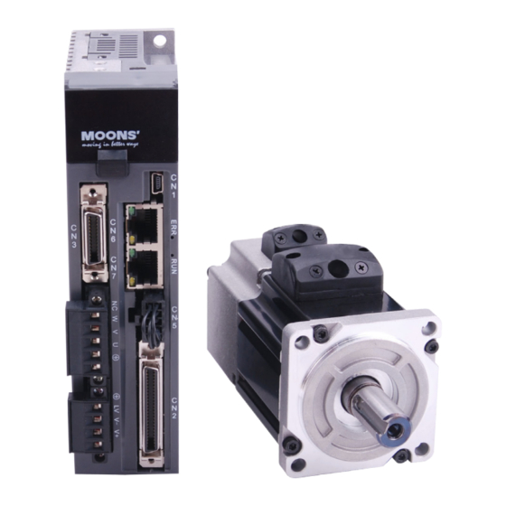
- Page 1 M2DC Series DC Servo System Hardware Manual Rev. 1.1 SHANGHAI AMP&MOONS’ AUTOMATION CO.,LTD.
-
Page 2: Table Of Contents
M2DC Series Hardware Manual Table of Contents 1 Introduction ........................8 1.1 About This Manual ......................8 1.2 Documentation Set for the M2DC Series Servo Drive ............8 1.3 Safety ..........................8 1.4 Safety Symbols .......................8 1.5 Safety Instructions ......................9 1.6 Guideline for Parts Replacement ..................9 1.6.1 Parts Replacement ....................9... - Page 3 M2DC Series Hardware Manual 4.2.2.1 PIN Assignment ......................30 4.2.2.2 Motor Connector Specifications ................30 4.2.2.3 Motor Extension Cable Wiring Diagram ..............31 4.2.3 Motor Power Cable Connector(-CF Winding,10 and 20Amps) ......31 4.2.3.1 PIN Assignment ......................31 4.2.3.2 Motor Extension Cable Wiring Diagram ..............32 4.3 Encoder Connector CN3 ....................33...
- Page 4 M2DC Series Hardware Manual 4.9.5 Encoder Feedback Output ..................53 4.9.5.1 A/B/Z Connection Diagram ..................53 4.9.5.2 Z Phase Open Collector Output ................53 5 Display and Operation ....................54 5.1 Control Panel Description....................54 5.2 Mode Switch Control ......................55 5.3 LED display description ....................56 5.3.1 Decimal Point And Negative Sign Description ............56...
- Page 5 M2DC Series Hardware Manual 7.2.2 Input Pulse Type And Input Noise Filter ...............80 7.2.3 Control Pulse Dividing Switch ................82 7.2.4 Pulse Inhibit ......................83 7.2.5 Electronic Gearing Ratio ..................84 7.2.6 Jerk Smoothing Filter ....................85 7.2.7 In-Position Error Output ..................85 7.2.8 Gain Parameters For Position Control Mode ............86 7.2.9 Software Configuration For Position Mode ............87...
- Page 6 9.3.2 Communication Address ..................142 9.3.3 Communication Baud Rate And Framing .............142 9.3.4 Power Up Mode ....................143 9.3.6 M2DC series Servo Drive Register Addresses and Function List: .......143 9.3.7 Command Opcode Description ................151 9.3.8 Function Code ......................153 9.3.9 Modbus/RTU Applications ...................156 9.4 CANopen Communication .....................162...
- Page 7 M2DC Series Hardware Manual Revision History Document History Date Remarks v1.0 2016.06.20 Add M2DC-20D drvie v1.1 2018.04.20 Disclaimer The information in this manual was accurate and reliable at the time of its release. MOONS’ reserves the right to change the specifications of the product described in this manual without notice at any time.
-
Page 8: Introduction
1.1 About This Manual This manual describes the M2DC Servo Drive. It provides the information required for installation, configuration and basic operation of the M2DC series servo drive. This document is intended for persons who are qualified to transport, assemble, commission, and maintain the equipment described herein. -
Page 9: Safety Instructions
M2DC Series Hardware Manual 1.5 Safety Instructions Installation DO NOT subject the product to water, corrosive or flammable gases, or combustibles. DO NOT use the motor in a place subject to excessive vibration or shock. Never connect the motor directly to the AC power supply. -
Page 10: Bearing Life
M2DC Series Hardware Manual Product Component Standard replacement cycle Notes Smoothing condenser Approx. 6 years These hours or cycles Aluminum electrolytic Approx. 6 years are for reference only. capacitor (on PCB) Occurence of error, Drive Approx. 100,000 uses (depending Rush current preventive... -
Page 11: Standards Compliance
M2DC Series Hardware Manual 1.7 Standards Compliance The M2DC Series Servo drive has been designed according to flowing standard: * Electromagnetic compatibility Standard EN 61800-3 Rev. 1.1 400-820-9661 2018/04... -
Page 12: Product Description
M2DC Series Hardware Manual 2 Product Description 2.1 System Checklist A complete and workable M2DC servo system should include the following parts: 1. A matched servo drive and servo motor (refer section 2.4 for recommended combinations) 2. A power cable with a 4-PIN connector to connect P1 (V+, V-, AUX+) to supply power to the drive 3. -
Page 13: Drive Specifications
M2DC Series Hardware Manual 2.2.3 Drive specifications 20 - 70VDC Main Circuit M2DC-6D0 M2DC-10D Input Power 10 - 70VDC Control Circuit M2DC-20D Ambient temperature: 0°C to 50°C (if the ambient temperature of the servo drive is greater than 40°C, please install the drive in a well-ventilated location) Temperature Storage temperature: -20°C to 65°C... -
Page 14: Drive Dimensions (Unit: Mm)
M2DC Series Hardware Manual 2.2.4 Drive Dimensions (Unit: mm) □ M2DC-6D0/10D 28.5 R2.5 □ M2DC-20D 28.5 R2.5 Rev. 1.1 400-820-9661 2018/04... -
Page 15: Servo Motor Model Introduction
M2DC Series Hardware Manual 2.3 Servo Motor Model Introduction 2.3.1 Motor Name Plate Description Mode NO. Series NO. Input Ouyput Power Rated Torque,speed Max. Speed Ins.Class 2.3.2 Motor Model Description S M 06 02 F E4 - K C F - N N V... -
Page 16: Motor Specifications And Dimensions
M2DC Series Hardware Manual 2.3.3 Motor Specifications and Dimensions 2.3.3.1 40mm Specifications and Dimensions UL File E465363 Insulation Class Class B (130) IP65 (except shaft through hole and cable end IP rating connector) Indoors, away from direct sunlight, corrosive Installation location gas, flammable gas Operating 0 to 40°C, Storage -20 to 65°C... - Page 17 M2DC Series Hardware Manual 40mm Dimensions Motor Dimensions – No Brake: mm Motor Dimensions – Brake: mm 0.04 A 0.04 Oil seal Oil seal +0.20 +0.20 - 0.13 - 0.13 25 1 L1 1 25 1 L1 1 0.04 0.04 A...
-
Page 18: 60Mm Specifications And Dimensions
M2DC Series Hardware Manual 2.3.3.2 60mm Specifications and Dimensions UL File E465363 Insulation Class Class B (130) IP65 (except shaft through hole and cable end IP rating connector) Indoors, away from direct sunlight, corrosive Installation location gas, flammable gas Operating 0 to 40°C, Storage -20 to 65°C... - Page 19 M2DC Series Hardware Manual 60mm Dimensions Motor Dimensions – No Brake: mm Motor Dimensions – Brake: mm 0.04 A 0.04 A 50 h7 - 0.025 0.04 A 50 h7 - 0.025 0.04 A 22.5 oil seal 0.300 0.118 0.300 0.118 oil seal 口60...
-
Page 20: 80Mm Specifications And Dimensions
M2DC Series Hardware Manual 2.3.3.3 80mm Specifications and Dimensions UL File E465363 Insulation Class Class B (130) IP65 (except shaft through hole and cable end IP rating connector) Indoors, away from direct sunlight, corrosive Installation location gas, flammable gas Operating 0 to 40°C, Storage -20 to 65°C... - Page 21 M2DC Series Hardware Manual 80mm Dimensions Motor Dimensions – No Brake: mm Motor Dimensions – Brake: mm Motor Feedback 0.04 A 70 h7 - 0.03 0.04 A Ø 70 h7 - 0.03 4- Ø 6.5 19 h6 - 0.013 Ø 19 h6 - 0.013...
- Page 22 M2DC Series Hardware Manual M2DC Servo Motor Specifications and Dimensions—Frame 80mm Model SM0803GE4-KCF-NNV Recommanded Drive Input Voltage (DC-Bus) Rated Output Power watts Rated Speed 3000 Max. Speed 3600 Rated Torque Peak Torque Rated Current A (rms) 22.5 Peak Current A (rms) 56.5...
-
Page 23: Servo Drive And Servo Motor Combinations
M2DC Series Hardware Manual 2.4 Servo Drive and Servo Motor Combinations Servo Drive M2DC-6D05S Basic Type M2DC-10D5S M2DC-20D5S Q Program Type M2DC-6D05Q M2DC-10D5Q M2DC-20D5Q (RS-232 Communication) Q Program Type M2DC-6D05R M2DC-10D5R M2DC-20D5R (RS-485 Communication) M2DC-6D05C CANopen M2DC-10D5C M2DC-20D5C M2DC-6D05D eSCL... -
Page 24: Installation
M2DC Series Hardware Manual 3 Installation 3.1 Storage Conditions • Store properly packaged in a clean and dry environment,away from direct sunlight • Store in an ambient temperature range of -20°C to +65°C • Store where the relative humidity range is 10% to 85% with non-condensing •... -
Page 25: Installation Space
M2DC Series Hardware Manual 3.3 Installation Space Incorrect installation may result in a drive malfunction or premature failure of the drive and/or motor. Please follow the guidelines in this manual when installing the servo drive and motor. The M2DC servo drive should be installed perpendicular to the wall or in a control panel. -
Page 26: Motor Installation
M2DC Series Hardware Manual 3.4 Motor Installation • DO NOT strike the motor when installing it as the motor shaft or encoder may be damaged. • DO NOT use cables that have been soaked with water or oil. • Avoid a stress application to the cable outlet and connecting portion by bending. -
Page 27: Connections And Wiring
M2DC Series Hardware Manual 4 Connections and Wiring 4.1 Connecting to Peripheral Devices 4.1.1 System Configuration LED Display: The 5 digit, 7 segment LED shows the drive status and faults. Operation Panel: Function keys are used to perform status display, monitor and diagnose, function and parameter settings. -
Page 28: Servo Drive Connectors And Terminals
M2DC Series Hardware Manual 4.1.2 Servo Drive Connectors and Terminals Terminal Identification Description Details V+, V- Used to connect DC main circuit power Used to connect an auxiliary circuit power Ground Used to connect servo motor Terminal Wire color Description... -
Page 29: Wiring Methods For P1 Power Supply Connector
M2DC Series Hardware Manual 4.1.4 Wiring Methods for P1 Power Supply Connector Power for the M2DC servo drives comes from 2 different sources Function Input Power V+, V- 20 - 70VDC Main power supply Drive’s main power input When the main power supply is off,... -
Page 30: Wiring To The P2 Connector
M2DC Series Hardware Manual 4.2 Wiring to the P2 Connector 4.2.1 Motor Power Cable Configuration P2 interface of the drive Motor Motor power lead wire extension cable connector connector Signal Colour Yellow/Green Yellow Blue 4.2.2 Motor Power Cable Connector(-CD Winding ,6Amps) 4.2.2.1 PIN Assignment... -
Page 31: Motor Extension Cable Wiring Diagram
M2DC Series Hardware Manual 4.2.2.3 Motor Extension Cable Wiring Diagram Housing: 172159-1(AMP) Terminal: 170362-1(AMP) Drive side (P2) Housing for the motor Signal Color AMP 172159-1 5452571(Phoenix) Yellow Blue Yellow/Green Ensure U/V/W is wired in the order of RED/YELLOW/BLUE. 4.2.3 Motor Power Cable Connector(-CF Winding,10 and 20Amps) 4.2.3.1 PIN Assignment... -
Page 32: Motor Extension Cable Wiring Diagram
M2DC Series Hardware Manual Motor Connector Specifications(200/300/400/550W) Type Motor side (plug) Extension cable (housing) AMP 350779-1 AMP 350780-1 Housing AMP 350218-1 AMP 350536-1 Terminal Motor Connector Specifications(750W) Type Motor side (plug) Extension cable (housing) AMP 350779-1 AMP 350780-1 Housing AMP 350922-6... -
Page 33: Encoder Connector Cn3
M2DC Series Hardware Manual 4.3 Encoder Connector CN3 4.3.1 Motor Encoder Feedback Cable Configuration CN3 interface of the drive Encoder Motor encoder extension cable connector connector 4.3.2 Layout of CN3 Connector View A View B Pin NO. Symbol Description Encoder A+... -
Page 34: Connection To Motor Encoder
M2DC Series Hardware Manual 4.3.3. Connection to Motor Encoder Connect to 2500ppr Increment Encoder (9PIN AMP connector) Servo Drive CN3 Motor Encoder Shield Shield 4.3.4 Specifications of Encoder Connector A. -E4 Encoder Connector PIN Assignment View A PIN# Signal Colour... -
Page 35: Motor Encoder Extension Cable Wiring Diagram
M2DC Series Hardware Manual 4.3.5 Motor Encoder Extension Cable Wiring Diagram -E4 Encoder Encoder Cable Diagram Connect to drive Connect to Motor View A Drive Side Housing for the motor TYCO 3-22322346-1 Signal Color AMP 172161-1 or equialent A+/U+ Blue... -
Page 36: Sto Connector
M2DC Series Hardware Manual 4.4 STO Connector On the M2DC series servo drives, the STO (Safe Torque Off) function is connected via port CN5. The STO function shuts off the motor current turning off the motor output torque by forcibly turning off the signal of the servo driver power transistor. -
Page 37: Sto Signal Definition
M2DC Series Hardware Manual 4.4.2.3 STO Signal Definition Signal Symbol Description Control Mode When SF1 has no input signal, e.g. SF1+ the port is disconnected, SF1 will be Safety Input SF1 considered OFF. The upper half of the SF1- internal power transistor will be shut off. -
Page 38: Electromagnetic Brake
M2DC Series Hardware Manual 4.5 Electromagnetic Brake When the motor drives the vertical axis, a brake should be used to hold and prevent the load from falling by gravity when the power is removed. NOTE: Use only a servo motor brake for holding a load when the motor is disabled or the power is off. -
Page 39: Regeneration Resistor
M2DC Series Hardware Manual 4.6 Regeneration Resistor In M2DC-6D5 or M2DC-10D servo drives, there is a pre-installed 20W regeneration resistor. In some applications, the pre-installed regeneration resistor might not be enough to absorb all foldback current and get a over-voltage fault. In these cases, a larger wattage regeneration resistor needs to be connected to P3 connector port externally, to prevent drive over voltage warnings. -
Page 40: Recommended Cable Specifications
4.9 Input and Output Signal Interface Connector - CN2 4.9.1 Input and Output Interface Specifications and Diagram Port CN2 on the M2DC series servo drives is used for input/output signals. Details are shown in table below: 8 Configurable optically isolated general inputs, 5-24VDC, 20mA... -
Page 41: Signal Description Of Connector Cn2
M2DC Series Hardware Manual 4.9.2 Signal Description of Connector CN2 Analog Input ANA1 Speed Command PULSH1 DGND PULSH2 High Speed ANA2 Pulse Input Torque Command SIGNH1 DGND SIGNH2 37 Y1+ Alarm Output 36 Y1- STEP/CW Position Motor Brake Command Control Output... -
Page 42: Layout Of Cn2 Connector
View A 4.9.2.2 Input Signals The M2DC series servo drive has 12 programmable digital inputs as well as 2 analog inputs. Each of the inputs can be specified with different functions via the parameter settings. The functions are as follows: ●... -
Page 43: Input Function List
M2DC Series Hardware Manual High-speed pulse inputs (+5VDC line drive input), the maximum input frequency 2MHz. PULSH1 Three pulse commands available: PULSH2 ● Pulse & Direction High-Speed ● CW Pulse and CCW Pulse SIGNH1 Pulse Inputs ● A Quadrature B pulse... -
Page 44: Output Signals
M2DC Series Hardware Manual 4.9.2.4 Output Signals The M2DC series servo drive has 6 programmable digital output signals available; each of the outputs can be specified with a different function via parameter settings. Signal Symbol Pin NO. Details This output has two functions: ●... -
Page 45: Input Signal Interface Connector, Cn2
4.9.3 Input Signal Interface Connector, CN2 4.9.3.1 Position pulse signal input The M2DC series servo has two high speed pulse intputs, STEP/DIR and PULSH/SIGNH. STEP/DIR supports 5-24VDC, up to 500KHz open collector input signal or differential input signal through the line driver. -
Page 46: Analog Signal Input For Velocity And Torque Mode
4.9.3.2 Analog Signal Input For Velocity And Torque Mode The M2DC series servo drive has 2 single ended analog inputs OR 1 differential analog input. The input voltage range is -10V to +10V. Velocity and torque range can be configured via M Servo Suite software. -
Page 47: High Speed Input Ports X1, X2, X3, X4
M2DC Series Hardware Manual Differential Analog Input Host PC Differential Analog Control Mode D/A Output DGND DGND 4.9.3.3 High Speed Input Ports X1, X2, X3, X4 High Speed Input Port The M2DC has 4 optically isolated high speed digital inputs X1, X2, X3, and X4. These inputs allow input voltage from 5VDC to 24VDC with maximum current of 20mA, and up to 500KHz. - Page 48 M2DC Series Hardware Manual High Speed Input Connection Diagrams HOST controller 5-24VDC 5-24VDC HOST controller X1\2\3\4+ X1\2\3\4+ X1\2\3\4- X1\2\3\4- 0VDC 0VDC Host Sink Mode Host Sourcing Mode 5-24VDC X1\2\3\4+ X1\2\3\4+ +5-24VDC Power Output sensor X1\2\3\4- connection X1\2\3\4- Relay Or Switch...
-
Page 49: General Digital Input X5, X6, X7, X8
M2DC Series Hardware Manual 4.9.3.4 General Digital Input X5, X6, X7, X8 The M2 has 4 optically isolated general digital inputs X5, X6, X7 and X8. These inputs allow input voltage from 5VDC to 24VDC, with maximum input current of 20mA up to 5KHz. Both single ended and differential signals are allowed. - Page 50 M2DC Series Hardware Manual X5, X6, X7, X8 Input Port Connection Diagrams HOST controller 5-24VDC 5-24VDC HOST controller X5\6\7\8+ X5\6\7\8+ X5\6\7\8- X5\6\7\8- 0VDC 0VDC Host Sink Mode Host Sourcing Mode 5-24VDC X5\6\7\8+ X5\6\7\8+ +5-24VDC Power Output X5\6\7\8- sensor connection X5\6\7\8-...
-
Page 51: X9, X10, X11, X12 Inputs With Common Com Port
M2DC Series Hardware Manual 4.9.3.5 X9, X10, X11, X12 Inputs with common COM Port The M2 drives also have 4 single ended optically isolated inputs connected with a single common node named ‘COM’. These inputs can be used with sourcing or sinking signals, 12-24V. This allows for connection to PLCs, sensors, relays and mechanical switches. -
Page 52: Cn2 Output Signal Specification
4.9.4 CN2 Output Signal Specification The M2DC series servo drives feature 6 optically isolated digital outputs. They can be configured via M Servo Suite. Y1, Y2, Y5, and Y6 are differential output signals, they can be used for both sourcing or sinking signals. -
Page 53: Encoder Feedback Output
M2DC Series Hardware Manual 4.9.5 Encoder Feedback Output The M2DC series servo drive can output encoder A/B/Z phase as differential output signals through the line driver. The output signal is 5V, A/B signals are 10000 pulse/rev, Z signal is 1 pulse/rev. -
Page 54: Display And Operation
M2DC Series Hardware Manual 5 Display and Operation 5.1 Control Panel Description LED Display MODE DOWN Symbol Name Details The LCD display (5 digits, 7 segments) shows the drive’s operating LED Display condition, warning codes, parameters, and setting values. Press and hold MODE button to switch the LED display mode... -
Page 55: Mode Switch Control
M2DC Series Hardware Manual 5.2 Mode Switch Control • button changes between status monitoring, function control, Pressing the button and the parameters setting and other modes. • If no warnings or faults occur, the drive will not go into warning and fault display mode. -
Page 56: Led Display Description
M2DC Series Hardware Manual NOTE: • When power is applied, the drive’s display will show the customer defined monitoring mode. In factory default mode, it will display the motor’s rotary velocity. • When in parameter setting mode, pressing the button will exit the parameter setting mode, and return back to parameter selection mode, without saving any changes. -
Page 57: Point To Point Motion Mode
M2DC Series Hardware Manual 5.3.4 Point To Point Motion Mode LED display Description When the LED display reads “P-CW” it means the motor is rotating in a CW direction in the point-to-point mode. When the LED display reads “P-CCW” it means the motor is rotating in a CCW direction in the point-to-point mode. -
Page 58: Status Monitoring Selection Mode
M2DC Series Hardware Manual 5.4 Status Monitoring Selection Mode To change the status monitoring mode, press to enter monitoring selection mode, and then use to make selections, and press to confirm, as below: Power ON Default display is current motor velocity... - Page 59 M2DC Series Hardware Manual n-09 Fault History 2 n-10 Fault History 3 n-11 Fault History 4 n-12 Fault History 5 n-13 Fault History 6 n-14 Fault History 7 n-15 Fault History 8 0.001VDC n-16 Differential Analog Input 0.001VDC n-17 Analog Input 1 0.001VDC...
-
Page 60: Function Control Mode
M2DC Series Hardware Manual 5.5 Function Control Mode In function control mode (display F+ parameter number), you can select functions for preoperational mode, restart the drive, enable or disable the drive, etc. In status monitoring mode, press and hold for 1 to select function, and then press and hold second to enter function control mode. -
Page 61: Operation Flow Chart
M2DC Series Hardware Manual 5.5.2 Operation Flow Chart status monitoring selection press and hold MODE key for 1 second press and hold SET key F-00 point to point mode function selection mode press ,motor rotate 1 rev in CW direction... -
Page 62: Parameter Setting Mode
M2DC Series Hardware Manual 5.6 Parameter Setting Mode 5.6.1 Parameter Setting Description The parameter setting mode (P+parameter number) allows you to select, display and edit the required parameter. In function control mode, press and hold for 1 second to enter parameter setting mode. -
Page 63: Parameter Editing Examples
M2DC Series Hardware Manual 5.6.2 Parameter Editing Examples Press mode to First digit flash Second digit flashing shift flashing digit Press Press Press Press Press up or down to increase or decrease value Press SET key to enter parameter editing mode... -
Page 64: Control Panel Lock
M2DC Series Hardware Manual 5.7 Control Panel Lock To prevent unauthorized use of the key panel, a key panel lock is featured on all M2DC servo drives. When the panel is locked, no function can be changed directly on drive’s control panel. - Page 65 M2DC Series Hardware Manual LED display Description LED display Description Drive over temperature CW limit is activated Internal voltage fault CCW limit is activated Over voltage Current limit Communication error Over current Parameter save failed STO is activated Bad hall sensor...
-
Page 66: Preoperational Mode
M2DC Series Hardware Manual 6 Preoperational mode When using preoperational mode, disconnect the servo motor from any mechanical system to prevent damages and accidents. Preoperational mode should be used only under a no load condition. 6.1 Inspection Before Trial Run To avoid any accidents and damages to the servo drive and mechanical systems, the following safety checks are recommend before the drive is turned on. -
Page 67: Motor Configuration
M2DC Series Hardware Manual 6.3 Motor Configuration Before using JOG mode, the drive needs to be properly configured for the connected motor. This can be done through the drive control panel or the M Servo Suite software. For more details about motor specifications, refer to Section 2.3. -
Page 68: Using M Servo Suite Software For Configuration
M2DC Series Hardware Manual 6.3.2 Using M Servo Suite Software for configuration Run the M Servo Suite software on a PC, and (1) select the correct communication port. Use the drive configuration tab (2) to set up the motor. Click the Config button to bring up the Motor Select screen: After setting the required parameters, click OK and then Download All to Drive to save the settings to the drive. -
Page 69: Operations Of Jog Mode
M2DC Series Hardware Manual 6.4 Operations of JOG Mode Step LED display Description to switch from Monitor Status mode to the Drive Parameters Configuration mode Press Scroll with the keys to select parameter P62 (SI) Press key to enter the value setting mode... -
Page 70: Configuration By Personal Computer
M2DC Series Hardware Manual 6.5 Configuration by Personal Computer To ensure the M2DC servo drive and motor meet operational requirements, it is recommended that the M Servo Suite software is used for the following configuration setups: • Servo motor model selection and configuration •... -
Page 71: Operation Mode Selection
M2DC Series Hardware Manual 7 Operation Mode Selection 7.1 General Function Settings 7.1.1 Drive Servo On Settings To control servo motor enable/disable switch 1) Servo ON signal By default, the Servo ON input (X3) is configured as follows: Function Signal Name... -
Page 72: Alarm Reset
M2DC Series Hardware Manual 7.1.2 Alarm Reset The Alarm Reset is used to clear drive warnings or faults and is set via P-63 (AI) Signal P-63 (AI) Function Name (CN2) During normal operation, input X4 must be kept Open (HIGH). -
Page 73: Cw/Ccw Limit
M2DC Series Hardware Manual 7.1.3 CW/CCW limit In order to prevent damage that might be caused by mechanical hardware accidentally moving out of range, it is highly recommended that the CW/CCW position limits be configured by using external end-of- travel sensors connected to inputs X5 and X6. -
Page 74: Global Gain Selection
M2DC Series Hardware Manual Software Configuration On the Drive Configuration page - Input& Output, select X5/X6 functions to set up 7.1.4 Global Gain Selection Use input X7 for the Global Gain selection. This gain selection function is used to dynamically configure the servo drive to run the motor with the least time delay and as close as possible to the host command. -
Page 75: Control Mode Selection
7.1.5 Control Mode Selection M2DC series servo drives allows to the choice of 2 types of control modes to be selected by using external input X8. The control modes can be configured via two parameters P-12 (CM) and P-13 (CN). -
Page 76: Drive On Fault Output
M2DC Series Hardware Manual 7.1.6 Drive On Fault Output When faults occur, the drive will send an “On-Fault” output and it will also immediately disable the drive. Faults include: position error, encoder error, over temperature, over voltage, low voltage, internal voltage fault, STO warning, FPGA error, over current, over velocity limit, bad hall sensor. -
Page 77: Motor Brake Control
M2DC Series Hardware Manual 7.1.7 Motor Brake Control A servo motor brake is only to be used for holding the load when the motor is disabled or powered OFF. It ensures the motor’s rotor (and connected load) will NOT move due to gravity or any other external forces. -
Page 78: Servo Ready Output
M2DC Series Hardware Manual 7.1.8 Servo Ready Output When the servo drive is powered on, if no faults are present, the Y3 output can be configured output a “servo ready” signal. This servo ready function can be configured via M Servo Suite software, or by changing parameter P-68 (MO) the first digit (from right to left) on the drive’s control panel. -
Page 79: Position Mode
M2DC Series Hardware Manual 7.2 Position Mode Position mode is widely used in applications where precise positioning is required. In M2DC series servo drives there are 3 types of position mode: digital pulse position mode, analog position mode and position table mode. -
Page 80: Input Pulse Type And Input Noise Filter
M2DC Series Hardware Manual 7.2.2 Input Pulse Type And Input Noise Filter There are three types of pulse modes: STEP & Direction; CW/CCW Pulse; A/B Quadrature. Parameter P-43 (SZ) uses decimal numbers to define pulse input type, polarity and input filter frequency. - Page 81 M2DC Series Hardware Manual 7.2.2.3 Parameter P-43 (SZ) Setting Parameter P-43 (SZ)’s higher 8 digits and lower 8 digits set the definition for input filter frequency and pulse type, the setting values are as shown in table below: Filter P-43 (SZ)
-
Page 82: Control Pulse Dividing Switch
M2DC Series Hardware Manual Software Configuration On the Motor Configuration page - Control Mode Settings select pulse input type and input filter type. 7.2.3 Control Pulse Dividing Switch Input X9 is used as the control pulse dividing switch function. When this function is on, it will allow the drive to change the number to encoder counts per motor revolution. -
Page 83: Pulse Inhibit
M2DC Series Hardware Manual 7.2.4 Pulse Inhibit The Pulse Inhibit function uses external input X10 in digital pulse position mode. When external input X10 is triggered, it will force the drive to stop receiving pulse input from any source, and stop the servo motor immediately. -
Page 84: Electronic Gearing Ratio
M2DC Series Hardware Manual 7.2.5 Electronic Gearing Ratio The host command pulse count per revolution times the electronic gearing ratio set on the drive will result in the actual number of pulses per revolution at the motor shaft. This feature allows more freedom and set... -
Page 85: Jerk Smoothing Filter
M2DC Series Hardware Manual 7.2.6 Jerk Smoothing Filter Applying this dynamic filter on speed and direction signals can significantly smoothing motor rotary motion, and reduce wear on mechanical system components. Jerk smoothing filter effects are as follows: Instruction Target Curve Actual Curve 1) The smaller the value of P-07 (KJ), the stronger the effect will be. -
Page 86: Gain Parameters For Position Control Mode
M2DC Series Hardware Manual 7.2.8 Gain Parameters For Position Control Mode In position mode, proper gain parameters will cause the servo system to run and stop more smoothly, and accurately, thereby optimizing its performance. In most cases, M Servo Suite’s auto tuning function will help to automatically tune these parameters. -
Page 87: Software Configuration For Position Mode
M2DC Series Hardware Manual 7.2.9 Software Configuration For Position Mode The M Servo Suite can help easily configure the drive and motor, and optimize the tuning parameters. Step Operation Description Configure motor Step Choose your motor model. Refer to Section 2.3 for motor details. -
Page 88: Velocity Mode
M2DC Series Hardware Manual 7.3 Velocity Mode The velocity control mode is used for applications that require precise velocity control. For M2DC series servo drives, they are 4 types of velocity control mode: fixed-speed mode, analog command mode, SCL control mode and multi-velocity control mode. Fixed-speed mode will set the motor running at a constant speed. -
Page 89: Velocity Mode Connection Diagram
M2DC Series Hardware Manual 7.3.1 Velocity Mode Connection Diagram Analog Input ANA1 Speed Command ±10VDC PULSH1 DGND PULSH2 ANA2 Torque Command ±10VDC SIGNH1 17 DGND SIGNH2 37 Y1+ Alarm Output 36 Y1- RUN/STOP Brake Control Output 10 Y2- 40 Y5+... -
Page 90: Parameter Settings For Analog Velocity Control Mode
7.3.2 Parameter Settings For Analog Velocity Control Mode The M2DC series servo drive has 2 12-bit analog A/D converters. When a single-ended input signal is used, analog input 1 (ANA1) is used for the velocity command, and analog input 2 (ANA2) is used for the torque limit setting. -
Page 91: Basic Settings For Analog Velocity Control Mode
M2DC Series Hardware Manual 7.3.3 Basic Settings For Analog Velocity Control Mode 7.3.3.1 Command Signal For Analog Velocity Mode In Analog input velocity mode, both single-ended and differential connection types are acceptable. Single Ended Analog Input Function PIN type Signal... - Page 92 M2DC Series Hardware Manual 7.3.3.2 Analog Velocity Gain Analog input voltage range is between -10V~+10V. In analog velocity, setting the velocity value and correspondent input voltage value is required. This can be set via M Servo Suite software or P-50 (AG) on the drive’s control panel.
- Page 93 M2DC Series Hardware Manual 7.3.3.4 Analog Input Deadband In analog control model, even when the input voltage is 0V, it is almost impossible to ensure that the input voltage is absolute 0V due to external interferences. In some cases, it might cause the motor to turn slowly in either direction.
- Page 94 M2DC Series Hardware Manual 7.3.3.6 Torque Limit In single-ended analog mode, analog input 2 (ANA2) can used to set motor’s output torque. Parameter Settings Data Default Parameter Name Unit Description Range value Analog input type P-55 (AS) Analog type 0: Single ended input 1: Differential input...
- Page 95 M2DC Series Hardware Manual 7.3.3.7 Target Velocity Reached In velocity mode, when the motor’s actual velocity and commanded target velocity are the same, the “velocity reached” output signal can be sent by output Y4 . The second digit (from right to left) of parameter P-68 (MO) defines the output signal Y4.
-
Page 96: Analog Input Filter
M2DC Series Hardware Manual 7.3.4 Analog Input Filter When the analog input is used, there can be external signal interference that will affect the accuracy of the analog input voltage. In some cases will cause the motor to turn unexpectedly, or cause unstable torque output. -
Page 97: Software Configuration For Analog Velocity Mode
M2DC Series Hardware Manual 7.3.5 Software Configuration for Analog Velocity Mode The M Servo Suite software easily configures the drive and motor, and optimizes the tuning parameters. Step Operation Description Configure motor Step Choose your motor model. Refer to Section 2.3 for motor details. -
Page 98: Torque Mode
M2DC Series Hardware Manual 7.4 Torque Mode Torque mode is normally used for applications that require precise torque control. For M2DC series servo drives, there are 2 types of torque control mode: analog input torque mode and SCL command mode. For analog command mode, torque is controlled by external voltage input. -
Page 99: Analog Torque Mode Connection Diagram
M2DC Series Hardware Manual 7.4.1 Analog Torque Mode Connection Diagram Analog Input ANA1 Speed Command ±10VDC PULSH1 DGND PULSH2 ANA2 High Speed Pulse Input Torque Command ±10VDC SIGNH1 17 DGND SIGNH2 37 Y1+ Alarm Output 36 Y1- RUN/STOP Brake Control Output... -
Page 100: Parameters For Analog Torque Mode
7.4.2 Parameters For Analog Torque Mode M2DC series servo drives have 2 12-bit analog A/D converters. When single-ended input signals are used, analog input 1 (ANA1) is used for the velocity command, and analog input 2 (ANA2) is used for the rotating toque command. -
Page 101: Basic Settings For Analog Torque Mode
M2DC Series Hardware Manual 7.4.3 Basic Settings For Analog Torque Mode 7.4.3.1 Command Signal For Analog Torque Mode In Analog input torque mode, both single ended and differential signal are acceptable. Single Ended Analog Input Connector pin Function Pin Type... - Page 102 M2DC Series Hardware Manual 7.4.3.2 Analog Torque Gain Analog input voltage range is -10V to +10V. In analog torque mode, the drive must be told how much current is required for a given analog input voltage. This can be configured via M Servo Suite or parameter P-51 (AN) directly from the drive’s control panel.
- Page 103 M2DC Series Hardware Manual 7.4.3.4 Analog Deadband In analog control mode, even when the input voltage is 0V, it is impossible to ensure that the input voltage is absolutely zero due to external interference. In some cases, it might case motor turn slowly in either direction.
- Page 104 M2DC Series Hardware Manual 7.4.3.6 Velocity Limit In analog torque mode, if no limit is set on the motor’s velocity, and the load inertia is small, the motor’s velocity will be very fast, and could damage the machinery. Therefore, it is very important to set a velocity limit.
- Page 105 M2DC Series Hardware Manual 7.4.3.7 Target Torque Reached In torque mode, when the motor’s actual torque and commanded torque are the same, a “torque reached” output signal can be sent via the Y3 output. The first digit (from right to left) of parameter P-68 (MO) from the drive defines the output signal Y3.
-
Page 106: Software Configuration For Analog Torque Mode
M2DC Series Hardware Manual 7.4.4 Software Configuration for Analog Torque Mode The M Servo Suite can help you easily configure the drive and motor, and set the tuning parameters. Step Operation Description Configure motor Step Choose your motor model. Refer to Section 2.3 for motor details. -
Page 107: Position Table Mode
Instead, position table mode uses Input ports X7 - X12 to configure different position commands. Input X4 is the trigger for motion. NOTE: Only -S type M2DC series servo drive supports position table mode 7.5.1 Linear motion The Linear motion option for position table mode can set up to 63 positions, not including the homing position. -
Page 108: Basic Configuration
M2DC Series Hardware Manual • Click Edit for detailed motion configurations. 7.5.1.2 Basic Configuration Point Counts: Select the number of position Point Counts: 7, 15, 31, or 63. Position type: There are two types of point-to-point motion: Relative Position and Absolute Positon. -
Page 109: Homing Settings
M2DC Series Hardware Manual • Counts represents the number of pulses from the encoder output. For Position Table mode, one motor revolution is 10000 pulse counts. • Lead represents the distance for one motor revolution in units of mm/rev. 7.5.1.3 Homing settings Homing Method: There are 12 types of homing available. -
Page 110: Simulate
M2DC Series Hardware Manual M0(X7) - M5(X12) status: ‘0’ means the input is closed; ‘1’ means the input is open. After the homing process, the motor will move to the corresponding position selected by inputs M0(X7) - M5(X12), and triggered by X4 (position trigger) when it changes from ‘open’ to ‘closed’. -
Page 111: Rotary Motion
M2DC Series Hardware Manual 7.5.2 Rotary motion Rotary motion is useful for turntable (dividing plate) applications, allowing for a system gear reduction ratio setting that is based on the hardware. Settings such as the number of division per revolution, motion profiles and homing profiles can also be entered in the Rotary Mode configuration panel. -
Page 112: Rotary Motion Input Definition
M2DC Series Hardware Manual Division Ratio: Divide one revolution into that number of points with equal distance spacing Rotary direction: Selects the direction for rotary motion Rotary velocity, rotary acceleration, rotary deceleration: Set motor rotary velocity, rotary acceleration, and rotary deceleration values NOTE: These setting affect the motor’s velocity, acceleration, and deceleration. -
Page 113: Parameters And Functions
M2DC Series Hardware Manual 8 Parameters and Functions 8.1 Parameter Category M2DC series servo drives have 4 modes Function Type Example Details Select LED monitoring status Section 5.4 Status Monitoring n - Status Monitoring type Selection Mode Select drive function to F - Function Control Section 5.5 Function Control Mode... - Page 114 M2DC Series Hardware Manual Current Current Command of Torque Mode 0.01A config Current Rated Maximum current 0.5 * config Current Peak current 1.5 * config Profile Maximum velocity 110.000 Profile Maximum acceleration/deceleration 3000 rps/s Profile Jog speed 10.000 Profile Jog acceleration 100.00...
- Page 115 M2DC Series Hardware Manual Config In Position Error Range counts Config In position duration count counts Config Pulses Input Completion count Analog Analog Position Gain 8000 counts Analog Velocit Gain Analog 20.000 Analog Torque Gain Analog 1.00 Analog Analog input1 offset 0.000...
- Page 116 M2DC Series Hardware Manual Input X11 noise filter Input X12 noise filter Communication protocol communication Transmit delay communication Baud rate communication RS-485 Address communication CANopen Node ID communication CANopen Baudrate communication Ω Regen resistor value Regeneration Regen resistor continuous wattage...
- Page 117 M2DC Series Hardware Manual Follow factor P100 P101 Other Select motor rotation Rev. 1.1 400-820-9661 2018/04...
-
Page 118: Parameter Description
M2DC Series Hardware Manual 8.3 Parameter Description Data Range Default Unit Data type P-00 (KP) Global gain 1 0 - 32767 ------ 8000 Sets or requests the servo control proportional gain term. Gain value is relative: “0” meaning no gain, “32767”... - Page 119 M2DC Series Hardware Manual Data Range Default Unit Data type P-05 (KI) Integrator gain 0~32767 ------ The servo control integrator gain term. Gain value is relative: “0” meaning no gain, “32767” meaning full gain. It minimizes (or may even eliminate) position errors especially when holding position.
- Page 120 M2DC Series Hardware Manual Data Range Default Unit Data type P-08 (VP) Velocity Loop Proportional Gain 0~32767 ------ 15000 The velocity-mode servo control proportional gain term. Gain value is relative: “0” meaning no gain, “32767” meaning full gain. VP minimizes velocity error when in velocity mode 2.
- Page 121 M2DC Series Hardware Manual Analog torque mode: X1 for run/stop signal; Analog input torque +10 - -10V analog signal X2 is open, motor will change its current rotary mode direction. Analog torque mode: X1 for run/stop signal; Analog input torque...
- Page 122 M2DC Series Hardware Manual Data Range Default Unit Data type P-14 (PM) Power-up mode 2, 5, 7,8,9,10 ------ The power-up mode of the drive. PM determines how the drive is configured for serial communications at power-up. For example, for SCL applications set PM=2 or PM=5. The power-up mode can also be set when configuring the drive with Quick Tuner or ST Configurator.
- Page 123 M2DC Series Hardware Manual Data Range Default Unit Data type P-18 (CP) Peak current Depends on motor model CP sets the peak (RMS) current setting of the servo drive. Peak current sets the maximum current that should be used with a given motor. When the motor position requires more than the continuous value, the...
- Page 124 M2DC Series Hardware Manual Data Range Default Unit Data type P-23 (JA) Jog acceleration 0.167 - 5000 rps/s The accel/decel rate for Jog moves and velocity control mode in rev/sec/sec. Setting JA overwrites both the last JA and JL values. This means that to have different jog accel and jog decel values, you should first send JA to set the jog accel and then send JL to set the jog decel.
- Page 125 M2DC Series Hardware Manual Data Range Default Unit Data type P-28 (VC) speed change 0.025 - 100 The secondary speed for FC and FD moves. NOTE: if you need to view or set this value on the drive’s control panel, refer to the following calculation:...
- Page 126 M2DC Series Hardware Manual Data Range Default Unit Data type P-36 (JC) Jog mode speed 8 0.025 - 100 The eighth speed used in velocity mode. This only applies to control modes 13, 14, 17, and 18. Data Range Default...
- Page 127 M2DC Series Hardware Manual Data Range Default Unit Data type P-44 (PF) Position Fault limit 0 - 32000 2000 The position fault limit in encoder counts. This value defines the limit threshold, in encoder counts, reached between the actual position and the commanded position before the system produces a position fault error.
- Page 128 M2DC Series Hardware Manual Data Range Default Unit Data type P-50 (AG) Analog Velocity Gain -100.000 - 100.000 20.000 Analog gain value used in analog velocity modes. The gain value is used to establish the relationship between the analog input and the motor speed in units of 0.25 rpm. For example, if the analog input is scaled to 0 - 5 volt input and the gain is set to 2400, when 5 volts is read at the analog input the motor will spin at 10 rps.
- Page 129 M2DC Series Hardware Manual Data Range Default Unit Data type P-56 (AD) Analog input 1 deadband 0 - 255 The analog deadband value of analog input 1 in millivolts. The deadband value is the zone around the “zeroed” value of the analog input. This deadband defines the area of the analog input range that the drive should interpret as “zero”.
- Page 130 M2DC Series Hardware Manual Data Range Default Unit Data type P-61 (FA) Analog X1, X2 function 11 - 33 Defines the function of analog inputs X1 and X2, by two digits, from right to left. Digit 1: Input X1 function...
- Page 131 M2DC Series Hardware Manual Data Range Default Unit Data type P-64 (DL) End-of-travel limit Setting 1-3,7-12,17-20 CW and CCW end-of-travel limits are available on all drives and can be used to define the boundaries of acceptable motion in a motor/drive system.
- Page 132 M2DC Series Hardware Manual Data Range Default Unit Data type P-66 (AO) Alarm output function setting Defines usage of digital output Y1. Normally this output is used to indicate an Alarm caused by a Drive Fault. This output can being reconfigured as a general purpose output for use with other types of output commands.
- Page 133 M2DC Series Hardware Manual A: When the actual velocity reaches the targeted velocity, output Y3 is closed. B: When the actual velocity reaches the targeted velocity, output Y3 is open. 3: Output Y3 is used as a general purpose output.
- Page 134 M2DC Series Hardware Manual Data Range Default Unit Data type P-71 (FI) Input X9 noise filter 0 - 32767 Applies a digital filter to the input X9. The digital input must be at the same level for the time period specified by the FI command before the input state is updated.
- Page 135 M2DC Series Hardware Manual Bit 6: Checksum Type Bit 7: Little endian or big endian used in MODBUS type drive Bit 8: Four wires/two wires for RS-485 communication Data Range Default Unit Data type P-77 (TD) Transmit delay 0 - 100 The time delay used by the drive when responding to a command that requests a response.
- Page 136 M2DC Series Hardware Manual Data Range Default Unit Data type P-80 (CO) CANopen Node ID 1 - 127 The CANopen NODE-ID for CANOpen type drives. Also used for IP address selection on Ethernet drives. P-80(CO) P-80(CO) IP Address IP Address 10.10.10.10...
- Page 137 M2DC Series Hardware Manual Data Range Default Unit Data type Ripple range setting for velocity P-85 (VR) 0 - 136 reach 0.000 The velocity ripple value around the targeted velocity. If the difference between the actual velocity and targeted velocity is within the ripple value, the drive will define the actual velocity as having met the target velocity value.
- Page 138 M2DC Series Hardware Manual Data Range Default Unit Data type P-89 (DD) LED Default status monitor type 0 - 14 Sets or requests the default monitor status on the driver’s LED display. Data Range Default Unit Data type LED Warning Display Mask...
- Page 139 M2DC Series Hardware Manual Data Range Default Unit Data type Decel of seeking homing switch P-95 (HL) 0.167 - 5000 during homing rps/s In homing mode, after end-of-travel is reached, this sets the deceleration rate for seeking the homing switch. Refer to parameter P-91 (HA).
-
Page 140: Communication
M2DC Series Hardware Manual 9 Communication M2DC series servo drives support multiple communication interfaces Model type Communication RS-232 RS-485 CANopen Ethernet 9.1 RS-232 communication For Q type drives, port CN6 is the RJ-11 communication port for RS-232 communication. MOONS’ SCL serial command language can be used to control the drive. -
Page 141: Connection Method
M2DC Series Hardware Manual Pin definitions are as follows: Definition 4, 5, 7, 8 9.2.2 RS-485 Connection Method RS-422/485 communication allows connection of more than one drive to a single host PC, PLC, HMI or other computer. It also allows the communication cable to be long. The use of Category 5 cable is recommended as it is widely used for computer networks, is inexpensive, easily obtained and certified for quality and data integrity. -
Page 142: Modbus/Rtu Communication
ModbusRTU/ASCII can set the drive address from 1 to 9.3.3 Communication Baud Rate And Framing M2DC series servo drives have fixed communication data framing: 8 data bits, one stop bit, no pairty. The drive parameter P-77 (BR) defines the communication baud rate. -
Page 143: Power Up Mode
Normal Modbus response: response function code = request function code Modbus error response: response function code = request function code + 0x80 (providing an error code) 9.3.6 M2DC series Servo Drive Register Addresses and Function List: Register Access Data Type... - Page 144 M2DC Series Hardware Manual Register Access Data Type Description SCL Register 40015..16 Read Only LONG Immediate Position Error (IX) Immediate Analog Input Value (IA) 40017 Read Only SHORT Q Program Line Number 40018 Read Only SHORT 40019 Read Only SHORT Immediate Current Command (IC) 40020..21...
- Page 145 M2DC Series Hardware Manual Register Access Data Type Description SCL Register 40045..46 LONG Input Counter 40047 SHORT Jog Accel (JA) 40048 SHORT Jog Decel (JL) Jog Velocity (JS) 40049 SHORT Max Velocity 40050 SHORT 40051 SHORT Continuous Current(CC) 40052 SHORT...
- Page 146 M2DC Series Hardware Manual Register Access Data Type Description SCL Register User Defined Register 40083..84 LONG < User Defined Register 40085..86 LONG User Defined Register 40087..88 LONG > User Defined Register 40089..90 LONG User Defined Register 40091..92 LONG User Defined Register 40093..94...
- Page 147 M2DC Series Hardware Manual Register Access Data Type Description SCL Register 40118 SHORT Jog Change(JC) 40119 SHORT Jog Change(JC) 40120 SHORT Jog Change(JC) X9 Input Filter 40121 SHORT X10 Input Filter 40122 SHORT X11 Input Filter 40123 SHORT X12 Input Filter...
- Page 148 M2DC Series Hardware Manual Register Access Data Type Description SCL Register 40143 SHORT Control Mode(CM) 40144 SHORT Control Mode 1(CN) 40145 SHORT Operation Mode(PM) 40146 SHORT Jog Mode(JM) Hard-Stop Current Limit(HC) 40147 SHORT 40148 SHORT Max Acceleration(AM) 40149 Read Only...
- Page 149 M2DC Series Hardware Manual Register Access Data Type Description SCL Register 40166 SHORT Analog Deadband 2(AD2) 40167 SHORT Analog Deadband (AD) Analog Function(FA) 40168 SHORT 40169 SHORT Servo Enable(SI) 40170 SHORT Alarm Reset(AI) Define Limits Input(DL) 40171 SHORT 40172 SHORT...
- Page 150 M2DC Series Hardware Manual Register Access Data Type Description SCL Register 40190 SHORT Homing Deceleration 1 40191 SHORT Homing Deceleration 2 40192 SHORT Homing Deceleration 3 Homing Velocity 1 40193 SHORT Homing Velocity 2 40194 SHORT Homing Velocity 3 40195...
-
Page 151: Command Opcode Description
M2DC Series Hardware Manual 9.3.7 Command Opcode Description Register 40125 is defined as Command Opcode, when the following commands are entered into the register, the drive will execute the corresponding operation. 1) SCL Command Encoding Table SCL Command Encoding Table... - Page 152 M2DC Series Hardware Manual 2) Digital I/O Function Selection And I/O Status Character hex code ‘0’ 0x30 Index of encode ‘1’ 0x31 input 1 or output 1 ‘2’ 0x32 input 2 or output 2 ‘3’ 0x33 input 3 or output 3 ‘4’...
-
Page 153: Function Code
M2DC Series Hardware Manual 9.3.8 Function Code MOONS’ drives currently support the following Modbus function codes: 1) 0x03: Read holding registers 2) 0x04: Read input registers 3) 0x06: Write single registers 4) 0x10: Write multiple registers 9.3.8.1 Function Code 0X03, Reading Multiple Holding Registers To read the encoder’s actual position command to drive Node ID 1, the data address for the encoder’s... - Page 154 M2DC Series Hardware Manual 9.3.8.2 Function Code 0x06, Writing Single Register To set the motor rotary velocity 12.5 rps to drive Node ID 11, the corresponding register address is 40030. The write-in data value for the register will be 12.5 x 240 = 3000. In hexadecimal, it is 12CH.
- Page 155 M2DC Series Hardware Manual 9.3.8.3 Function Code 0X10, Writing Multiple Registers To write target distance 30000 into drive Node ID 10, the corresponding register address is 40031. Transferred into hexadecimal, it is 7530h. Communication Details are as follows: Command Message (Master)
-
Page 156: Modbus/Rtu Applications
M2DC Series Hardware Manual 9.3.9 Modbus/RTU Applications 9.3.9.1 Position Control Target Profile Planning Target Unit Dec (Hex) Description Value command , when target The unit for register 40028 is rps/s 40028 600 (258h) acceleration is 100rps/s, the value will be 600 The unit for register 40029 is . - Page 157 M2DC Series Hardware Manual Sending Command Set acceleration register 40028 = 285h deceleration register 40029 = 4B0h velocity register 40030 = 960h target position 40031 - 40032 = 4E20h Host Sending: 01 10 00 1B 00 05 0A 02 58 04 B0 09 60 00 00 4E 20 24 3B...
- Page 158 M2DC Series Hardware Manual Point To Point Motion Command Section 9.3.7 Command Opcode describes register 40125’s control code. The SCL code list shows that for point-to-point position motion, data 0x66 must be written to register 40125. SCL Command Encoding Table...
- Page 159 M2DC Series Hardware Manual 9.3.9.2 JOG mode JOG mode required parameters: Target Unit Dec (Hex) Description Value command , when target The unit for register 40028 is rps/s 40047 600 (258h) acceleration is 100rps/s, the value will be 600 The unit for register 40029 is .
- Page 160 M2DC Series Hardware Manual Sending Command Set velocity mode acceleration register as 40047 = 258h deceleration register as 40048 = 4B0h velocity register 40049 = 960h Host Sending: 01 10 00 2E 00 03 06 02 58 04 B0 09 60 A0 9F...
- Page 161 M2DC Series Hardware Manual Command Message (Master) Command Message (Slave) Function Function Data Number Of Bytes Data Number Of Bytes Slave Address Slave Address Function Code Function Code 00H (High) 00H (High) Starting Data Address Starting Data Address 7CH (Low)
-
Page 162: Canopen Communication
4, 5, 8 9.4.2 CANopen NODE-ID In the CANopen network, each drive needs to have a unique NODE-ID. For M2DC series servo drives, NODE-IDs can be set from 1-112. “0” cannot be used for ID setting. Parameter P-79 (CO) sets the NODE-ID. -
Page 163: Trouble Shooting
M2DC Series Hardware Manual 10 Trouble Shooting 10.1 Drive Alarm List LED display Description Alarm type Drive status after alarm occurs Fault Drive over temperature Servo off Fault Internal voltage fault Servo off Fault Over voltage Servo off Fault Servo off... - Page 164 Drive internal voltage failure. fault contact MOONS Drive DC bus voltage is too high M2DC series : Higher than 90VDC 1. Enter correct voltage. 1. Power supply voltage has exceeded the 2. Measure the resistance of the internal permissible input voltage.
- Page 165 M2DC Series Hardware Manual Please check motor velocity command if it is within the P-20(VM) range. 1. Avoid high velocity command 2. Check the command pulse input frequency and Position error division/multiplication ratio. Motor rotary velocity exceeds parameter P-20(VM) setting value.
-
Page 166: Appendix
M2DC Series Hardware Manual Appendix Appendix 1: LED Character Reference Appendix 2: Cables and Connectors Listed below are cables and connectors available from MOONS’ to make implementation of an M2DC servo system fast and easy. Encoder Cables See Section 4.3 for more information on wiring the connectors. - Page 167 M2DC Series Hardware Manual Encoder Cables ◆ Standard Type Description Drive Side M2 Common Encoder Cable, Shielded, 1m 2627-100 Motor Side M2 Common Encoder Cable, Shielded, 3m 2627-300 M2 Common Encoder Cable, Shielded, 5m 2627-500 A View M2 Common Encoder Cable, Shielded, 10m 2627-1000 ◆...
- Page 168 M2DC Series Hardware Manual Motor Power Cable—M2DC-20D ◆ Standard Type Housing: 350780-1(AMP) Crimp: 350536-1(AMP) Description M2DC-20D Common Motor Cable, Shielded, 1m 1641-100 M2DC-20D Common Motor Cable, Shielded, 3m 1641-300 M2DC-20D Common Motor Cable, Shielded, 5m 1641-500 ◆ Flexible Motor Cable - Extra Type...
Need help?
Do you have a question about the M2DC Series and is the answer not in the manual?
Questions and answers