Sign In
Upload
Download
Table of Contents
Contents
Add to my manuals
Delete from my manuals
Share
URL of this page:
HTML Link:
Bookmark this page
Add
Manual will be automatically added to "My Manuals"
Print this page
×
Bookmark added
×
Added to my manuals
Manuals
Brands
Moons' Manuals
Servo Drives
STF Series
Hardware manual
Moons' STF Series Hardware Manual
Step motor drive
Hide thumbs
1
Table Of Contents
2
3
4
5
6
7
8
9
10
11
12
13
14
15
16
17
18
19
20
21
22
23
page
of
23
Go
/
23
Contents
Table of Contents
Bookmarks
Table of Contents
Table of Contents
Introduction
Features
Safety Instructions
Getting Started
Installing Software
Choosing a Power Supply
Voltage
Current
Connecting the Motor
Connecting the Ethercat
Ethercat Status Indicator Leds
Setting the Ethercat Node ID
LED Display
Inputs and Outputs
X3,X4,X5,X7,X8 Digital Inputs
Y1, Y2 Digital Outputs
Mounting the Drive
Reference Materials
Drive Mechanical Outlines
Technical Specifications
Recommended Motor
Torque Curves
Numbering System
Ordering Information
Accessories (Sold Separately)
RC-880 Regeneration Clamp
Bus Communication
USB Mini-B Cable
Contacting MOONS
Customer Service Center
Advertisement
Quick Links
Download this manual
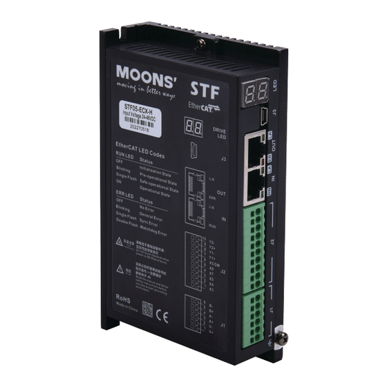
STF-ECX-H
Step Motor Drive
Hardware Manual
SHANGHAI AMP & MOONS' AUTOMATION CO.,LTD.
STF05-ECX-H
STF10-ECX-H
STF05-ECX-H-FC
STF10-ECX-H-FC
Rev.1.0
27/03/2024
Table of
Contents
Previous
Page
Next
Page
1
2
3
4
5
Advertisement
Table of Contents
Need help?
Do you have a question about the STF Series and is the answer not in the manual?
Ask a question
Questions and answers
Related Manuals for Moons' STF Series
Servo Drives MOONS’ SS03-S-A Hardware Manual
Ss series step-servo drive (44 pages)
Servo Drives MOONS’ SS-EC Series Hardware Manual
Step-servo ethercat drive (60 pages)
Servo Drives MOONS’ Applied Motion Products StepSERVO SSDC Series Hardware Manual
(52 pages)
Servo Drives MOONS’ Applied Motion Products StepSERVO SSDC06 Hardware Manual
(52 pages)
Servo Drives Moons' SSDC-D Series Hardware Manual
Step-servo system (51 pages)
Servo Drives Moons' SSDC-R Series Hardware Manual
Step-servo system (53 pages)
Servo Drives Moons' SSDC06-R Hardware Manual
Step-servo system (53 pages)
Servo Drives Moons' SSDC-A Series Hardware Manual
Step-servo system (49 pages)
Servo Drives Moons' SSDC-EC Series Hardware Manual
Step-servo system (50 pages)
Servo Drives Moons' SSDC Series Hardware Manual
Step-servo system (48 pages)
Servo Drives Moons' SSM24C User Manual
(50 pages)
Servo Drives Moons' Applied Motion Products SV7-C Quick Setup Manual
(2 pages)
Servo Drives Moons' SSM23C User Manual
Integrated step-servo motor (51 pages)
Servo Drives Moons' SSDC-4X-ECX Series Hardware Manual
Step-servo system (42 pages)
Servo Drives Moons' MBDV Series Hardware Manual
Low voltage servo system (181 pages)
Servo Drives Moons' STF05-ECX-H Hardware Manual
Step motor drive (23 pages)
This manual is also suitable for:
Stf ecx-h series
Stf05-ecx-h
Stf10-ecx-h
Stf05-ecx-h-fc
Stf10-ecx-h-fc
Table of Contents
Print
Rename the bookmark
Delete bookmark?
Delete from my manuals?
Login
Sign In
OR
Sign in with Facebook
Sign in with Google
Upload manual
Upload from disk
Upload from URL


Need help?
Do you have a question about the STF Series and is the answer not in the manual?
Questions and answers