Table of Contents
Advertisement
Advertisement
Table of Contents

Related Manuals for Ruijie RG-S2915-L Series


Summary of Contents for Ruijie RG-S2915-L Series
- Page 1 Ruijie RG-S2915-L Series Switches Hardware Installation and Reference Guide...
-
Page 2: Copyright Statement
This document is provided “as is”. The contents of this document are subject to change without any notice. Please obtain the latest information through the Ruijie Networks website. Ruijie Networks endeavors to ensure content accuracy and will not shoulder any... -
Page 3: Obtaining Technical Assistance
It is intended for the users who have some experience in installing and maintaining network hardware. At the same time, it is assumed that the users are already familiar with the related terms and concepts. Obtaining Technical Assistance Ruijie Networks Website: https://www.ruijienetworks.com/ Technical Support Website: https://ruijienetworks.com/support... -
Page 4: Product Overview
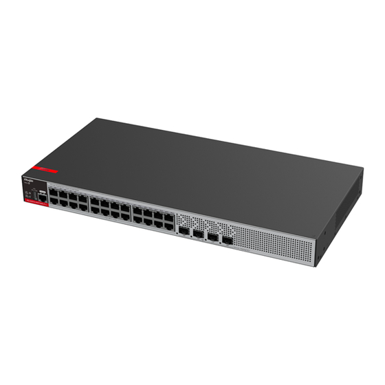
Product Overview 1 Product Overview RG-S2915-L series switches are the new-generation GE switches released by Ruijie Networks for campus access. With a brand-new hardware architecture and Ruijie RGOS11.X modular operating system, the RG-S2915-L series switches provide more resource entries, faster hardware processing performance, and better user experience. -
Page 5: Product Appearance
Hardware Installation and Reference Guide Product Overview Rated voltage range: 100 V AC to 240 V AC Maximum voltage range: 90 V AC to 264 V AC Frequency: 50 Hz/60 Hz Rated current: 0.6 A ≤ 3.5 mA Ground Leakage Current Support EEE Function Not Support... -
Page 6: Front Panel
Hardware Installation and Reference Guide Product Overview Front Panel Figure 1-2 Front Panel of RG-S2915-24GT4MS-L Switch Description: 1. System status LED 4. 10/100/1000Base-T adaptive Ethernet port 2. USB port 5. SFP port status LED 3. Console port 6. SFP port Back Panel Figure 1-3 Back Panel of RG-S2915-24GT4MS-L Switch Description:... -
Page 7: Power Supply
Hardware Installation and Reference Guide Product Overview Power Supply The RG-S2915-24GT4MS-L switch adopts an AC power supply. AC input: Rated voltage range: 100 V AC to 240 V AC; 50 Hz/60 Hz Maximum voltage range: 90 V AC to 264 V AC; 47 Hz to 63 Hz Frequency: 50 Hz/60 Hz Rated current: 0.6 A Power cord requirements: 10 A power cord... -
Page 8: Technical Specifications
BOOT ROM 64 MB Flash Memory SDRAM DDR4 512 MB Supported Modules See Appendix B The module types may be updated without prior notification. Please contact Ruijie Networks for details. 2500Base-X Capable SFP Port 1000Base-X Capable 100Base-FX Capable AC input:... - Page 9 Hardware Installation and Reference Guide Product Overview Operating Height 0 to 5000 m (3.11 miles) above the sea level Support fan speed control and fan fault alarm Temperature Alarming Support GB/T9254.1 EMC Certification GB4943 Safety Regulation Compliance 440 mm × 220 mm × 43.6 mm (17.32 in. × 8.66 in. × 1.72 in.), 1RU Dimensions (W ×...
- Page 10 Hardware Installation and Reference Guide Product Overview Figure 1-7 Back Panel of RG-S2915-48GT4MS-L Switch Description: 1. Grounding stud 3. Power plug 2. Power cord retention clip hole Power Supply The RG-S2915-48GT4MS-L switch adopts an AC power supply. AC input: Rated voltage range: 100 V AC to 240 V AC;...
- Page 11 BOOT ROM 64 MB Flash Memory DDR4 512 MB SDRAM See Appendix B Supported Modules The module types may be updated without prior notification. Please contact Ruijie Networks for details. SFP Port 2500Base-X Capable 1000Base-X Capable 100Base-FX Capable Power Supply...
- Page 12 Hardware Installation and Reference Guide Product Overview ≤ 15.6 W Overall Power Consumption Operating Temperature 0° C to 45° C (32° F to 113° F) at an altitude of 0-1800 m (1.12 miles) At an altitude of 1800 m to 5000 m (1.12 miles to 3.11 miles): The maximum temperature decreases by 1°...
- Page 13 Hardware Installation and Reference Guide Product Overview Description: 1. System status LED 4. 10/100/1000Base-T adaptive Ethernet port 2. USB port 5. SFP port status LED 3. Console port 6. SFP port Back Panel Figure 1-11 Back Panel of RG-S2915-16GT4MS-L Switch Description: 1.
- Page 14 Hardware Installation and Reference Guide Product Overview The switch should be installed at least 1 U (44.45 mm/1.75 in.) away from the neighbor device for normal heat dissipation. Panel Identification Status Description Blinking The system is being initialized. green Solid green The system is operating normally.
- Page 15 BOOT ROM Flash Memory 64 MB SDRAM DDR4 512 MB Supported Modules See Appendix B The module types may be updated without prior notification. Please contact Ruijie Networks for details. 2500Base-X Capable SFP Port 1000Base-X Capable 100Base-FX Capable Power Supply...
- Page 16 Hardware Installation and Reference Guide Product Overview Front Panel Figure 1-14 Front Panel of RG-S2915-10GT2MS-L Switch Description: 1. System status LED 4. 10/100/1000Base-T adaptive Ethernet port 2. USB port 5. SFP port status LED 3. Console port 6. SFP port Back Panel Figure 1-15 Back Panel of RG-S2915-10GT2MS-L Switch...
- Page 17 Hardware Installation and Reference Guide Product Overview Description: 1. Grounding stud 3. Power plug 2. Power cord retention clip hole Power Supply The RG-S2915-10GT2MS-L switch adopts an AC power supply. AC input: Rated voltage range: 100 V AC to 240 V AC; 50 Hz/60 Hz Maximum voltage range: 90 V AC to 264 V AC;...
- Page 18 BOOT ROM Flash Memory 64 MB SDRAM DDR4 512 MB Supported Modules See Appendix B The module types may be updated without prior notification. Please contact Ruijie Networks for details. 2500Base-X Capable SFP Port 1000Base-X Capable 100Base-FX Capable Power Supply...
- Page 19 Hardware Installation and Reference Guide Product Overview ≤ 3.5 mA Ground Leakage Current EEE Function Support PoE Function Ports 1-8 (RJ45 ports) are PoE/PoE+ capable. Maximum PoE/PoE+ output power: 125 W The maximum number of PoE devices supported by the switch is determined by the PoE output power of the switch and the actual power of the PoE devices.
- Page 20 Hardware Installation and Reference Guide Product Overview Front Panel Figure 1-18 Front Panel of RG-S2915-10GT2MS-P-L Switch Description: 1. System status LED 5. Console port 2. PoE status LED 6. 10/100/1000Base-T adaptive Ethernet port 3. PoE button 7. SFP port status LED 4.
- Page 21 Hardware Installation and Reference Guide Product Overview Description: 1. Grounding stud 3. Power plug 2. Power cord retention clip hole Power Supply The RG-S2915-10GT2MS-P-L switch adopts an AC power supply. AC input: Rated voltage range: 100 V AC to 240 V AC; 50 Hz/60 Hz Maximum voltage range: 90 V AC to 264 V AC;...
- Page 22 Hardware Installation and Reference Guide Product Overview Panel Identification Status Description Blinking The system is being initialized. green Solid green The system is operating normally. Solid yellow A system over-temperature alarm is generated. System status LED Status 1. The temperature severely exceeds the threshold, and the system will be reset and Solid red restart.
- Page 23 BOOT ROM Flash Memory 64 MB SDRAM DDR4 512 MB Supported Modules See Appendix B The module types may be updated without prior notification. Please contact Ruijie Networks for details. 2500Base-X Capable SFP Port 1000Base-X Capable 100Base-FX Capable Power Supply...
- Page 24 Hardware Installation and Reference Guide Product Overview Storage Humidity 5% to 90% RH Operating Height 0 to 5000 m (3.11 miles) above the sea level Support fan speed control and fan fault alarm Support Temperature Alarming GB/T9254.1 EMC Certification GB4943 Safety Regulation Compliance 440 mm ×...
- Page 25 Hardware Installation and Reference Guide Product Overview Description: 1. System status LED 5. Console port 2. PoE status LED 6. 10/100/1000Base-T adaptive Ethernet port 3. PoE button 7. SFP port status LED 4. USB port 8. SFP port You can press the port LED mode switching button (PoE button) to switch the port status indicator function (port PoE power supply indicator and port rate indicator).
- Page 26 Hardware Installation and Reference Guide Product Overview Panel Identification Status Description Blinking The system is being initialized. green Solid green The system is operating normally. System status LED Status Solid yellow A system over-temperature alarm is generated. 1. The temperature severely exceeds the Solid red threshold, and the system restarts.
-
Page 27: Preparing For Installation
Preparing for Installation 2 Preparing for Installation 2.1 Safety Precautions To avoid personal injury and device damage, carefully read the safety precautions before you install the RG-S2915-L series switches. The following safety precautions may not cover all possible dangers. 2.1.1 Installation Safety ... -
Page 28: Electrostatic Discharge Safety
2.1.5 Laser Safety The RG-S2915-L series switches support various types of optical modules available in the market and these optical modules are Class I laser products. Improper use of optical modules may cause damage. Therefore, pay attention to the following points when you use them: ... -
Page 29: Installation Environment Requirements
2.2 Installation Environment Requirements To ensure the normal operation and prolonged service life of the device, the installation site must meet the following requirements. You are not advised to install the RG-S2915-L series switches in a ELV box. 2.2.1 Ventilation and Cooling Requirements Maintain a minimum clearance of 10 cm (3.94 in.) on both sides of the chassis and around the back panel of the switch for normal air... -
Page 30: Anti-Interference Requirements
2.2.5 Grounding Requirements A proper grounding system is the basis for stable and reliable running of the RG-S2915-L series switches and is indispensable for preventing lightning strikes and interference. Carefully check the grounding conditions at the installation site according to the grounding specifications, and complete grounding properly based on the actual situation. -
Page 31: Emc Grounding
The resistance of the ground cable should be smaller than 1 ohm. Each of the RG-S2915-L series switches provides one grounding connector on the back panel, as shown in Figure 2-1. - Page 32 Hardware Installation and Reference Guide Preparing for Installation Electromagnetic interference (EMI) occurs due to electromagnetic radiation or conduction, depending on the transmission path. When the energy, often RF energy, from a component arrives at a sensitive component via the space, the energy is known as radiated interference.
-
Page 33: Installing The Switch
The installation environment meets the temperature and humidity requirements of the device. The power supply and required current are available in the installation site. The Ethernet cables have been deployed in the installation site. 3.3 Installing the RG-S2915-L Series Switches Precautions Pay attention to the following points during installation:... -
Page 34: Mounting The Switch To A Rack
Do not place anything on the RG-S2915-L series switches. Maintain sufficient ventilation space (more than 10 cm/3.94 in.) around the device to ensure good air circulation. Do not stack the device. -
Page 35: Mounting The Switch On A Wall
Hardware Installation and Reference Guide Installing the Switch Figure 3-3 Securing the Switch to the Rack 3.3.2 Mounting the Switch on a Wall You can also mount the RG-S2915-L switch on a wall with the provided mounting brackets. Take out the screws (delivered with the mounting bracket) from the packaging materials. Rotate the mounting brackets by 90 degrees, and secure the mounting brackets to the switch by using the screws. -
Page 36: Mounting The Switch On A Workbench
Hardware Installation and Reference Guide Installing the Switch Use expansion screws to secure the switch to a wall. Figure 3-5 Securing the Switch to the Wall If wall mount is adopted, the device can only be mounted on a concrete or non-flammable surface. 3.3.3 Mounting the Switch on a Workbench In many cases, users do not have a standard 19-inch rack. - Page 37 Hardware Installation and Reference Guide Installing the Switch Place the switch on a workbench and ensure adequate airflow around the switch. Figure 3-7 Mounting the Switch on the Workbench The location where the device is mounted and operated must be subject to movement restrictions. 3.4 Connecting a Grounding Cable Connect the PGND to the grounding lug of the cabinet and then connect the grounding lug to the grounding bar of the equipment room.
-
Page 38: Bundling The Cables
Hardware Installation and Reference Guide Installing the Switch The maintenance personnel should check whether the AC socket is reliably connected to the protection ground of the building. If not, the maintenance personnel should use a protection ground wire to connect the protection ground terminal of the AC socket to the protection ground of the building. - Page 39 Hardware Installation and Reference Guide Installing the Switch connection errors. Verify that the ground cable is connected. Verify that the cables and power input cables are correctly connected. Verify that the 100 m (328.08 ft.) Ethernet cable is routed indoors. If it is routed outdoors, verify that the AC lightning resistance socket and network interface lightning protector are connected.
-
Page 40: Setting Up The Configuration Environment
Hardware Installation and Reference Guide Verifying Operating Status 4 Verifying Operating Status 4.1 Setting up the Configuration Environment Setting up the Environment Connect a PC to the console port of the switch by using an Ethernet cable. Figure 4-1 Setting up the Environment Connecting the Cable Plug the DB-9 connector of the cable into the serial port of the PC. - Page 41 Hardware Installation and Reference Guide Verifying Operating Status Enter the name of the new connection and click OK, and a window appears as shown in Figure 4-3. Choose the serial port you want to use. Figure 4-3 After choosing the serial port, click OK to display the Serial Port Parameter Setting window as shown in Figure 4-4. Set the baud rate to 9600, data bit to 8, parity check to none, stop bit to 1 and flow control to none.
-
Page 42: Powering On The Switch
Hardware Installation and Reference Guide Verifying Operating Status After setting the parameters, click OK. 4.2 Powering on the Switch Checklist before Power-on Check that the switch is fully grounded. Check that the power cord is properly connected. Check that the power supply voltage meets the requirement of the switch. -
Page 43: General Troubleshooting Procedure
Possible Causes Solution You forget the login You forget the password after Please contact Ruijie Networks Customer Service password. manually configuring it. Department for technical support. Check whether the power socket in the equipment The status LED is off after ... - Page 44 Hardware Installation and Reference Guide Troubleshooting cooling. Change the serial port enabled on the The serial port connected to the configuration software to the serial port The serial port console switch is different from that enabled connected to the switch. has no output or outputs on the configuration software.
-
Page 45: Appendix A - Connectors And Connection Media
Hardware Installation and Reference Guide Appendix A — Connectors and Connection Media Appendix A — Connectors and Connection Media 1000BASE-T/100BASE-TX/10BASE-T Port 1000BASE-T/100BASE-TX/10BASE-T is a 10/100/1000M auto-negotiation port that supports auto MDI/MDIX Crossover. Compliant with IEEE 802.3ab, 1000BASE-T requires Category 5 or Category 5e 100-ohm UTP or STP (STP is recommended) with a maximum distance of 100 m. - Page 46 Hardware Installation and Reference Guide Appendix A — Connectors and Connection Media Please choose SMF or MMF optical fibers according to the optical module types. Figure A-4 shows the connection. Figure A-4 Optical Fiber Connection...
-
Page 47: Appendix B - Mini-Gbic Modules
Appendix B — Mini-GBIC Modules Ruijie provide supporting SFP modules (Mini-GBIC modules) based on the port types of switch modules. You can select a module to suit your specific needs. Besides, the Mini-GBIC-GT module is also supported. This document provides models and technical parameters of some 1000 M SFP modules for reference. - Page 48 Hardware Installation and Reference Guide Appendix B — Mini-GBIC Modules 50/125 550 m GE-eSFP-LX-SM1310 9/125 10 km GE-SFP-LX-SM1310 9/125 10 km MINI-GBIC-LH40-SM1310 9/125 40 km GE-SFP-SX-SM1310-BIDI 50/125 500 m GE-SFP-SX-SM1550-BIDI 50/125 500 m GE-SFP-LX20-SM1310-BIDI 9/125 20 km GE-SFP-LX20-SM1550-BIDI 9/125 20 km GE-SFP-LH40-SM1310-BIDI 9/125 40 km...
- Page 49 Hardware Installation and Reference Guide Appendix B — Mini-GBIC Modules 2.5G-SFP-LX03-SM1550-BIDI-I BIDI optical modules must be used in pairs. If GE-SFP-LX20-SM1310-BIDI is used at one end, then GE-SFP-LX20-SM1550-BIDI must be used at the other end.
-
Page 50: Appendix C - Lightning Protection
Hardware Installation and Reference Guide Appendix C — Lightning Protection Appendix C — Lightning Protection Installing AC Power Arrester (lightning protection cable row) The external lightning protection cable row shall be used on the AC power port to prevent the switch from being struck by lightning when the AC power cable is introduced from the outdoor and directly connected to the power port of the switch. - Page 51 Hardware Installation and Reference Guide Appendix C — Lightning Protection Tools: Cross or straight screwdriver, Multimeter, Diagonal pliers Installation Steps: Tear one side of the protection paper for the double-sided adhesive tape and paste the tape to the framework of the Ethernet port arrester.
- Page 52 Hardware Installation and Reference Guide Appendix C — Lightning Protection the switch grounding terminal. Use the multimeter to confirm the contact condition after the grounding. Incomplete arrester installation. If there is more than one port connected to the peer device on the switch, it needs to install the arresters on all connection ports for the purpose of the lightning protection.
-
Page 53: Appendix D - Cabling Recommendations In Installation
Appendix D — Cabling Recommendations in Installation When RG-S2915-L series switches are installed in standard 19-inch cabinets, the cables are tied in the binding rack on the cabinet by the cabling rack, and top cabling or bottom cabling is adopted according to the actual situation in the equipment room. All cable connectors should be placed at the bottom of the cabinet in an orderly manner instead of outside the cabinet easy to touch. - Page 54 Hardware Installation and Reference Guide Appendix D — Cabling Recommendations in Installation Cables of different types (such as power cords, signal cables, and grounding cables) should be separated in cabling and bundling. When they are close, crossover cabling can be adopted. In the case of parallel cabling, power cords and signal cables should maintain a space equal to or greater than 30 mm.
- Page 55 Hardware Installation and Reference Guide Appendix D — Cabling Recommendations in Installation during commissioning. The power cords cannot be bundled on the guide rails of moving parts. The power cables connecting moving parts such as door grounding wires should be reserved with some access after assembled. When the moving part reaches the installation position, the remaining part should not touch heat sources, sharp corners, or sharp edges.
- Page 56 Hardware Installation and Reference Guide Appendix D — Cabling Recommendations in Installation 80-150 10-30 150-200 200-300 No knot is allowed in cabling or bundling. For solder-less terminal blocks (such as air switches) of the cold pressing terminal type, the metal part of the cold pressing terminal should not be exposed outside the terminal block when assembled.
-
Page 57: Appendix E - Site Selection
Hardware Installation and Reference Guide Appendix E — Site Selection Appendix E — Site Selection The machine room should be at least 5 km away from the heavy pollution source such as the smelter, coal mine and thermal power plant, 3.7 km away from the medium pollution source such as the chemical industry, rubber industry and electroplating industry, and 2 km away from the light pollution source such as the food manufacturer and leather plant.
Need help?
Do you have a question about the RG-S2915-L Series and is the answer not in the manual?
Questions and answers