Table of Contents
Advertisement
Quick Links
Advertisement
Table of Contents

Related Manuals for Ruijie RG-S1920 Series


Summary of Contents for Ruijie RG-S1920 Series
- Page 1 Ruijie RG-S1920 Series Switches Hardware Installation and Reference Guide V1.11...
-
Page 2: Copyright Statement
This document is provided “as is”. The contents of this document are subject to change without any notice. Please obtain the latest information through the Ruijie Networks website. Ruijie Networks endeavors to ensure content accuracy and will not shoulder any responsibility for losses and damages caused due to content omissions, inaccuracies or errors. -
Page 3: Obtaining Technical Assistance
It is intended for the users who have some experience in installing and maintaining network hardware. At the same time, it is assumed that the users are already familiar with the related terms and concepts. Obtaining Technical Assistance Ruijie Networks Website: https://www.ruijienetworks.com/ Technical Support Website: https://ruijienetworks.com/support... -
Page 4: Product Overview
Hardware Installation and Reference Guide Product Overview 1 Product Overview Table 1-1 RG-S1920 10/100/1000 10/100 Base-T Base-T 1000Base-X SFP Model Auto-sensing Console Port Auto-sensing Port Ethernet Port Ethernet Port RG-S1920-18GT2SFP 4 (Ports 25-26 are RG-S1920-24GT4SFP/2GT Combo ports) The SPF ports are downward compatible with 100Base-FX. The application of 100Base-FX requires 100M SFP modules. -
Page 5: Product Appearance
Hardware Installation and Reference Guide Product Overview Operating Humidity 10% to 90% RH Storage Humidity 5% to 95% RH Not supported Temperature Not supported Warning Collecting Information of SFP Not supported Modules EMC Standards GB9254-2008 Security Standards GB4943-2011 Input Leakage ≤... -
Page 6: Back Panel
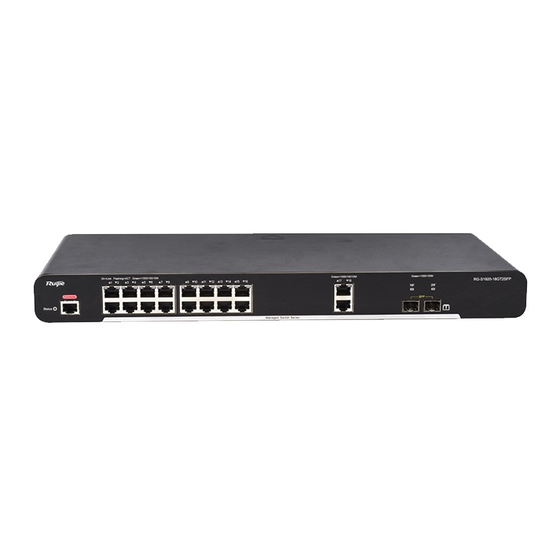
Hardware Installation and Reference Guide Product Overview Note 1. System status LED 5. Copper port status LED 2. Console port 6. 10/100/1000Base-T auto-sensing Ethernet port 3. 10/100/1000Base-T auto-sensing Ethernet port 7. SFP port status LED 4. Copper port status LED 8. - Page 7 Hardware Installation and Reference Guide Product Overview The port is receiving or transmitting traffic at Blinking green 10/100/1000 Mbps. The port is not connected. 1000Mbps SFP port Solid green The port is connected at 100/1000 Mbps. 19F-20F status LED The port is receiving or transmitting traffic at Blinking green 100/1000 Mbps.
- Page 8 Hardware Installation and Reference Guide Product Overview Information of SFP Modules EMC Standards GB9254-2008 Security Standards GB4943-2011 Input Leakage ≤ 1.5 mA Current Dimensions 440 mm x 189 mm x 43.6 mm (W x D x H) Weight 2.4 kg (with package) The RG-S1920-24GT4SFP/2GT switch is a class A product.
- Page 9 Hardware Installation and Reference Guide Product Overview Back Panel Figure 1-6 Back Panel of RG-S1920-24GT4SFP/2GT Note Grounding pole Power cord retention clip Vent AC power port Heat Dissipation The RG-S1920-24GT4SFP/2GT adopts natural heat dissipation, thereby ensuring normal function of the device in the specified environment.
-
Page 10: Preparation Before Installation
2 Preparation before Installation 2.1 Safety Suggestions To avoid personal injury and equipment damage, please carefully read the safety suggestions before you install the RG-S1920 series switch. The following safety suggestions do not cover all possible dangers. 2.1.1 Installation ... -
Page 11: Static Discharge Damage Prevention
Proper humidity conditions 2.1.5 Laser The RG-S1920 series switch supports varying models of optical modules sold on the market which are Class I laser products. Improper use of optical modules may cause damage. Therefore, pay attention to the following when you use them: ... -
Page 12: Temperature And Humidity
2.2.2 Temperature and Humidity To ensure the normal operation and prolong the service life of RG-S1920 series switch, you should keep proper temperature and humidity in the equipment room. If the equipment room has temperature and humidity that do not meet the requirements for a long time, the equipment may be damaged. -
Page 13: Safety Grounding
2.2.4 Grounding A good grounding system is the basis for the stable and reliable operation of the RG-S1920 series switch. It is the chief condition to prevent lightning stroke and resist interference. Please carefully check the grounding conditions on the installation site according to the grounding requirements, and perform grounding operations properly as required. -
Page 14: Lightning Resistance
All the above constitute the comprehensive grounding requirements. The resistance of earth wires should be less than 1 ohm. The RG-S1920 series switch back plane is reserved with one grounding pole, as shown in Figure 2-1. Figure 2-1 Grounding of RG-S1920 2.2.5 Lightning Resistance... -
Page 15: Requirements Of Installation Tools
Hardware Installation and Reference Guide Preparation before Installation Interface cables should be laid inside the equipment room. Outdoor cabling is prohibited, avoiding damages to device signal interfaces caused by over-voltage or over-current of lightning. 2.3 Requirements of Installation Tools Table 2-4 List of Installation Tools Phillips screwdriver, flathead screwdriver, related electric cables and optical cables, bolts, diagonal Common Tools... -
Page 16: Product Installation
Hardware Installation and Reference Guide Product Installation 3 Product Installation Please ensure that you have carefully read Chapter 2. Make sure that the requirements set forth in Chapter 2 have been met. 3.1 Installation Flowchart 3.2 Confirmations before Installation Before installation, please confirm the following points: ... - Page 17 3.3.1 Mounting the Switch to a Standard 19-inch Rack The RG-S1920 series switches follow the EIA standard dimensions and can be installed in 19-inch distribution cabinets. Attach the mounting brackets to the switch with the supplied screws, as shown in Figure 3-1 .
-
Page 18: Mounting The Switch On The Wall
Product Installation 3.3.2 Mounting the Switch on the Wall The RG-S1920 series switch can be mounted on the wall, as shown in the following figures. Attach the mounting brackets to the switch with the supplied screws, as shown in Figure 3-4. -
Page 19: Checking After Installation
Hardware Installation and Reference Guide Product Installation Place the switch on the table, as shown in Figure 3-7. Figure 3-7 Mounting the Switch on the Table The device must be installed and operated in the place that can restrict its movement. 3.4 Checking after Installation Before checking the installation, switch off the power supply so as to avoid any personal injury or damage to the component due to connection errors. -
Page 20: System Debugging
Hardware Installation and Reference Guide System Debugging 4 System Debugging 4.1 Establishing the Debugging Environment Establishing the Debugging Environment Connect the PC to the console port of the switch through the console cable, as shown in Figure 4-1. Figure 4-1 Schematic Diagram of the Configuration Environment Connecting the Console Cable ... - Page 21 Hardware Installation and Reference Guide System Debugging Enter the name of the new connection and click OK, the interface as shown in Figure 4-3 is displayed. Choose the serial port used currently in the column [use when connecting]. Figure 4-3 After choosing the serial port, click OK to display the serial port parameter setting interface, set the baud rate to 9600, data bit to 8, parity check to none, stop bit to 1 and flow control to none.
-
Page 22: Startup Check
Hardware Installation and Reference Guide System Debugging After setting the parameters, click OK to enter the hyper terminal interface. 4.2 Startup Check 4.2.1 Checking before the Device is Powered on The switch is fully grounded. The power cable is correctly connected. ... - Page 23 Hardware Installation and Reference Guide System Debugging Check whether the service interface forwards data normally.
-
Page 24: Maintenance And Troubleshooting
5.2 Troubleshooting Common Faults Symptom Possible Causes Solution Forgetting the A password is manually configured but Please contact Ruijie Networks Customer Service management interface it is forgotten. Department for technical support. login password The status indicator is The power supply module does not... - Page 25 Hardware Installation and Reference Guide Maintenance and Troubleshooting receiving/transmitting The port has special configuration that frames. has no common working mode with the connected switch. The Rx and Tx ends are connected Switch the Rx and Tx ends of the optical fiber. reversely.
-
Page 26: Appendix A: Connectors And Connection Media
Hardware Installation and Reference Guide Appendix A: Connectors and Connection Media Appendix A: Connectors and Connection Media 1000BASE-T/100BASE-TX/10BASE-T Ports The 1000BASE-T/100BASE-TX/10BASE-T is a port that supports adaptation of three rates, and automatic MDI/MDIX Crossover at these three rates. The 1000BASE-T complies with IEEE 802.3ab, and uses the cable of 100-ohm Category-5 or Supper Category-5 UTP or STP, which can be up to 100 m. -
Page 27: Optical Fiber Connection
Hardware Installation and Reference Guide Appendix B: Mini-GBIC Module Optical Fiber Connection For the optical fiber ports, select single-mode or multiple-mode optical fibers for connection according to the fiber module connected. The connection schematic diagram is shown in Figure A-4: Figure A-4 Optical Fiber Connections... -
Page 28: Appendix B: Mini-Gbic Module
You can select the Mini-GBIC module to suit your specific needs. The models and technical specifications of some Mini-GBIC modules are listed below. For details, see Ruijie Transceiver Installation and Reference Guide. Table B-1 Models and Technical Specifications of the 1000M Mini-GBIC(SFP) Module... - Page 29 Hardware Installation and Reference Guide Appendix B: Mini-GBIC Module Mini-GBIC-ZX100 1550 SDH155-SFP-SX-MM850 SDH155-SFP-SX-MM1310 1310 SDH155-SFP-LH15-SM1310 1310 SDH155-SFP-LH40-SM1310 1310 SDH155-SFP-LH80-SM1550 1550 GE-SFP-SX -9.5 GE-SFP-LX 1310 -9.5 Table B-2 Models of 1000M SFP Copper Module Standard Model DDM (Yes/No) 1000Base-T Mini-GBIC-GT Table B-3 Module Cabling Specification Model Connector Type Fiber Type...
- Page 30 Hardware Installation and Reference Guide Appendix C: Lightning Protection For the optical module with transmission distance exceeding 40 km and more, one on-line optical attenuator should be added on the link to avoid the overload of the optical receiver when short single-mode optical fibers are used. Optical modules generate laser.
-
Page 31: Appendix C: Lightning Protection
Hardware Installation and Reference Guide Appendix C: Lightning Protection Appendix C: Lightning Protection Installing AC Power Arrester (lightning protection cable row) The external lightning protection cable row shall be used on the AC power port to prevent the switch from being struck by lightning when the AC power cable is introduced from the outdoor and directly connected to the power port of the switch. - Page 32 Hardware Installation and Reference Guide Appendix C: Lightning Protection During the switch usage, the Ethernet port arrester shall be connected to the switch to prevent the switch damage by lightning before the outdoor network cable connects to the switch. Tools: Cross or straight screwdriver, Multimeter, Diagonal pliers Installation Steps: Tear one side of the protection paper for the double-sided adhesive tape and paste the tape to the framework of the Ethernet port arrester.
- Page 33 Hardware Installation and Reference Guide Appendix D: Cabling Recommendations in Installation Reversed direction of the arrester installation. You shall connect the external network cable to the “IN” end and connect the switch Ethernet port to the “OUT” end. Poor arrester grounding.
-
Page 34: Appendix D: Cabling Recommendations In Installation
Appendix D: Cabling Recommendations in Installation When RG-S1920 series switches are installed in standard 19-inch cabinets, the cables are tied in the binding rack on the cabinet by the cabling rack, and top cabling or bottom cabling is adopted according to the actual situation in the equipment room. - Page 35 Hardware Installation and Reference Guide Appendix D: Cabling Recommendations in Installation Cables of different types (such as power cords, signal cables, and grounding cables) should be separated in cabling and bundling. When they are close, crossover cabling can be adopted. In the case of parallel cabling, power cords and signal cables should maintain a space equal to or greater than 30 mm.
- Page 36 Hardware Installation and Reference Guide Appendix D: Cabling Recommendations in Installation Figure D-3 Bundling Up Cables (3) Cables not to be assembled or remaining parts of cables should be folded and placed in a proper position of the cabinet or cabling slot. The proper position indicates a position that will not affect device running or cause device damage or cable damage during commissioning.
- Page 37 Hardware Installation and Reference Guide Appendix D: Cabling Recommendations in Installation The hard power cable should be fastened by the terminal connection area to prevent stress. Do not use self-tapping screws to fasten terminals. Power cables of the same type and in the same cabling direction should be bundled up into cable bunches, with cables in cable bunches clean and straight.
-
Page 38: Appendix E: Site Selection
Hardware Installation and Reference Guide Appendix E: Site Selection Appendix E: Site Selection The machine room should be at least 5km away from the heavy pollution source such as the smelter, coal mine and thermal power plant, 3.7km away from the medium pollution source such as the chemical industry, rubber industry and electroplating industry, and 2km away from the light pollution source such as the food manufacturer and leather plant.
Need help?
Do you have a question about the RG-S1920 Series and is the answer not in the manual?
Questions and answers