
Related Manuals for Ruijie RG-S2900 Series


Summary of Contents for Ruijie RG-S2900 Series
- Page 1 Installation Manual RG-S2900 Series Full Gigabit Security Intelligent Access Switch...
- Page 2 The information contained in this manual may be modified without notification. Ruijie Networks has tried its best to maintain the accuracy and reliability of this manual on the website.Ruijie Networks takes no responsibility for the miss, inaccuracy or error and the resulting damage and loss in this manual.
-
Page 3: Table Of Contents
Contents Product Overview ..........................1-1 Major Usage and Applications ....................1-1 Key Features ..........................1-1 Appearance ..........................1-2 Technical Specifications ........................2-1 Product Installation..........................3-1 Installation Procedure ......................3-1 Confirmation Before Installation .................... 3-2 Installing the RG-S2924G/S2927XG/S2951XG Series ............3-2 3.3.1 Precautions ........................ - Page 5 Switch Software Manual——covering CLI commands, software configuration guide, and version release notes. Obtaining Documentation You can obtain the documentation you need through the following channels: Internet: You can obtain the latest on-line documentation of Ruijie Networks at: http://www.ruijie.com.cn Documentation CD-ROM:...
- Page 6 The documentation of Ruijie Networks switches is stored in the CD-ROM package, which is provided to you together with the product you purchase. The CD-ROM is updated frequently, and may be more current than the printed documents. Obtaining Technical Assistance Ruijie Networks provides excellent technical support services for all our products.
-
Page 7: Product Overview
Hardware Manual Chapter 1 Product Overview Product Overview Major Usage and Applications Ruijie's full gigabit security intelligent access switch is your optimal choice in the following cases: Access and convergence layer of small/middle-sized networks, such as university, educational institute, enterprise, government, finance, hospital and broadband IP premises network. -
Page 8: Appearance
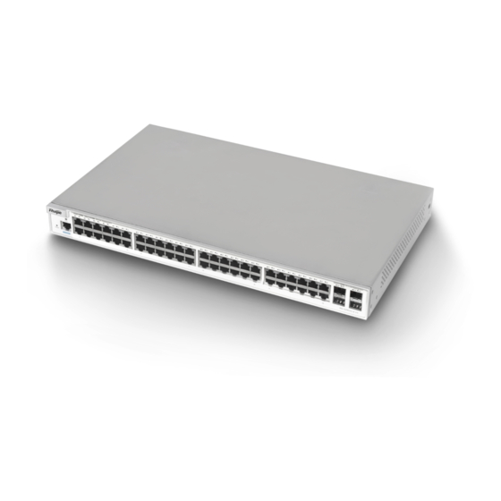
Chapter 1 Product Overview Hardware Manual The S2951XG switch provides a switching capacity up to 156G. Its L2 packet forwarding rate as much as 116.07Mpps (64 bytes) allows nonblocked switching for the users. The RJ45 port supports the MDI/MDIX auto-recognizing function. The SFP port supports many kinds of SFP modules and the SFP hot-plugging function. - Page 9 Hardware Manual Chapter 1 Product Overview Figure 1-1 Appearance of the S2924G Table 1-1 Identification of the front panel of the S2924G Identification Description Detailed Information OFF: The switch has not been powered on Power Power LED Solid green: The switch is working normally. Connected with the terminal or PC via the Console Management port...
- Page 10 Chapter 1 Product Overview Hardware Manual Table 1-3 Ports on the front panel of the S2927XG Identification Description Detailed Information OFF: Switch is not powered on Power Power LED Solid green: The switch is working normally. Connected with the terminal or PC via the Console Management port configuration cable to configure the switch...
- Page 11 Hardware Manual Chapter 1 Product Overview Identification Description Detailed Information Connected with the terminal or PC via the Console Management port configuration cable to configure the switch Green: Port is up 1000M network port Link/ACT Flashing: indicating data transmission Off: No module Orange: Module detected M1,M2,M3 10G port LED...
-
Page 13: Technical Specifications
Hardware Manual Chapter 2 Technical Specifications Technical Specifications Description Specifications IEEE802.3, IEEE802.1x, IEEE802.1p, IEEE802.3ae Protocol supported IEEE802.1Q, IEEEE802.1d, IEEE802.1W IEEEE802.1S, IGMPv1/v2/v3 Snooping SNMPv1/v2c/v3, Telnet, Web-based , Console, CLI, RMON Management mode S2924G: 20 10/100/1000 M RJ45 ports and 4 SFP 1000M combo ports (supports 1000BASE-SX/LX,1000BASE-TX,1000BASE-LH) S2927XG: 20 10/100/1000 M RJ45 ports and 4 SFP 1000M combo ports (supports 1000BASE-SX/LX,1000BASE-TX,1000BASE-LH);... - Page 14 Chapter 2 Technical Specifications Hardware Manual Description Specifications S2924G: Power, Link/ACT LED indicators S2927XG: Power, Link/ACT, Model S2951XG: Power, Link/ACT, Model S2924G :440 mm × 260 mm ×44 mm Dimensions S2927XG:440 mm × 350 mm ×44 mm ( W x D x H) S2951XG:440 mm ×...
-
Page 15: Product Installation
Hardware Manual Chapter 3 Product Installation Product Installation Please ensure that you have carefully read Chapter 2. Make sure that the requirements set forth in Chapter 2 have been met Note Installation Procedure Install the RG-S29 to the rack Connect the system Grounding Install various modules (if required) Connect the power supply... -
Page 16: Confirmation Before Installation
Chapter 3 Product Installation Hardware Manual Confirmation Before Installation Before installation, please confirm the following points: Whether sufficient airflow is available for the switch Whether the requirements of the switch for temperature and humidity are met Whether power cables are already laid out and whether the current requirements are ... - Page 17 Hardware Manual Chapter 3 Product Installation During the installation, place the front panel of the switch to the rack. For the satefy purposes, screw up the distributed screws as shown in the Figure3-1. Figure3-1 With handles contained: First, fasten the accessory provided in the carton for rack mounting to both sides of the switch.
-
Page 18: Mounting The Switch To The Wall
Chapter 3 Product Installation Hardware Manual Figure 3-3 Fastening the switch onto the rack Mounting the Switch to the Wall 3.3.3 If the supplemented hangers of the switch has four installation holes, then this switch supports the installation on walls, as shown in the following figure. Figure 3-4 Mounting the Switch to the Desktop 3.3.4... -
Page 19: Checking After Installtion
Hardware Manual Chapter 3 Product Installation Figure 3-5 Installing hangers There are screw holes on the hanger, during the installation, press the hanger onto the side wall of the switch. Checking After Installtion Before checking the installation, switch off the power supply so as to avoid any personal injury or damage to the component due to connection errors. - Page 20 Chapter 3 Product Installation Hardware Manual Before cleaning the switch, the power plug shall be pulled out. Use the dampened cloth to wipe. Do not place the switch besides the water area or in the humid area, and prevent the water any moisture from entering the switch enclosure.
-
Page 21: Troubleshooting
The system login password of the switch is forgotten or lost, and so it is not possible to configure the data. [Troubleshooting] Please contact Customer Service Department of Ruijie Networks for technical support. Fault 2: The AC power module does not work. [Fault Description] The Power indicator is not on and the fan does not run. - Page 22 Chapter 4 Troubleshooting Hardware Manual Fault 3: Link indicator is not on after the connection. [Fault Description] The LINK indicator is not lit for the port after the network cable or optical fiber is inserted. [Troubleshooting] Check whether the switch and the connecting devices are powered on. Verify the network cable is connected properly to the switch and related devices at both ends.
- Page 23 RG-S2900 Software Configuration Guide. If not, modify the serial port configuration parameters. If there is still no serial port printed information, please contact Customer Service Department of Ruijie Networks for technical support.
-
Page 25: Connectors And Connection Media
Hardware Manual Appendix A Connectors and Connection Media Connectors and Connection Media 1000BASE-T/100BASE-TX/10B ASE-T Port The 1000BASE-T/100BASE-TX/10BASE-T is a port that supports adaptation of three rates, and automatic MDI/MDIX Crossover at these three rates. The 1000BASE-T complies with IEEE 802.3ab, and uses the cable of 100-ohm Category-5 or Supper Category-5 UTP or STP, which can be up to 100m. -
Page 26: Optical Fiber Connection
Appendix A Connectors and Connection Media Hardware Manual Figure A-2 Pinouts of the 100BASE-TX/10BASE-T Figure A-3 shows the connections of the straight-through and crossover twisted pairs of the 100BASE-TX/10BASE-T. Figure A-3 Connections of the twisted pairs of the 100BASE-TX/10BASE-T Crossover Straight-Through Optical Fiber Connection For the optical fiber ports, select single-mode or multiple-mode optical fibers for connection... -
Page 27: Sfp (Mini-Gbic) Modules
Hardware Manual Appendix B SFP (Mini-GBIC) Modules SFP (Mini-GBIC) Modules We provide the appropriate 1000M SFP module (Mini-GBIC module) in according to the types of interfaces of the switch modules. You can select the SFP module to suit your specific needs. Below the models and technical specifications of some 1000M SFP modules are listed for your reference.
Need help?
Do you have a question about the RG-S2900 Series and is the answer not in the manual?
Questions and answers