Table of Contents
Advertisement
Quick Links
Advertisement
Table of Contents

Subscribe to Our Youtube Channel
Related Manuals for Ruijie RG-S2600E Series


Summary of Contents for Ruijie RG-S2600E Series
- Page 1 Installation Manual RG-S2600E Series...
- Page 2 Ruijie Networks Ltd. and are protected by law. Disclaimer The information contained in this manual may be modified without notification. Ruijie Networks has tried its best to maintain the accuracy and reliability of this manual on the website. Ruijie Networks takes no responsibility for the...
-
Page 3: Table Of Contents
1.1 Product Overview ................................7 1.2 Main Technical Specifications of RG-S2600E ......................7 1.3 RG-S2600E Series Models ............................. 9 1.3.1 RG-S2628G-E Ethernet Switch ..........................9 1.3.2 RG-S2652G-E Ethernet Switch ..........................11 1.3.3 RG-S2628G-P Ethernet Switch ........................... 13 ... - Page 4 4.1.2 Connecting the Console Cable ..........................30 4.1.3 Setting Terminal Parameters ..........................30 4.2 Power-on Startup ................................30 4.2.1 Checking before Power-on ..........................30 4.2.2 Checking after Power-on (Recommended) ....................... 31 Chapter 5 Maintenance and Troubleshooting ..................32 ...
- Page 5 Documentation CD-ROM: The documentation of Ruijie Networks switches is stored in the CD-ROM package, which is provided to you together with the product you purchase. The CD-ROM is updated frequently, and may be more current than the printed documents.
- Page 6 Customer services email: service@ruijie.com.cn Documentation Conventions The symbols used in this document are described as below: This symbol draws the attention of readers to some suggestions and references. This symbol reminds readers to be alert of wrong operations that may lead to loss of data or damage to equipment.
-
Page 7: Chapter 1 Product Overview
Chapter 1 Product Overview 1.1 Product Overview The RG-S2600E series switches of Ruijie are mostly applied at the access layers of small- and medium-sized networks to provide line-speed exchanging and complete QoS services, and ensure the undelayed transmission of key data by applying different traffic classification rules to different services. The S2600E series provide flexible medium interfaces and can meet the connection requirements of different media in network constructions. - Page 8 Ethernet 1000M: Mini-GBIC-SX Mini-GBIC-LX Mini-GBIC-LH40 Mini-GBIC-ZX50 Mini-GBIC-ZX80 Mini-GBIC-ZX100 1000Base-T: Mini-GBIC-GT Note: the supported module type may change at any time. For the detailed change information, consult the Ruijie Networks. Extended Module Type M3000E-02SFP/GT M3000E-STACK SFP Port 100Base-X 1000Base-X RPS Type...
-
Page 9: Rg-S2600E Series Models
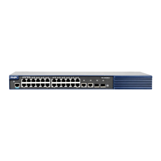
RG-S2652G-E: with extension modules 4.9 Kg and without extension modules 4.4 Kg RG-S2628G-P: with extension modules 7.5Kg and without extension modules 7.0 Kg RG-S2652G-P: with extension modules 8.1Kg and without extension modules 7.6 Kg 1.3 RG-S2600E Series Models 1.3.1 RG-S2628G-E Ethernet Switch Product Appearance The front panel of the RG-S2628G-E Ethernet switch provides twenty four 10/100Base-T Ethernet ports, two GE SFP fiber/copper combo ports and one Console port. - Page 10 Figure 1-1 Appearance of the RG-S2628G-E Ports on the Front Panel Figure 1-2 Schematic diagram of the RG-S2628G-E front panel 1. Switch status indicator 2. Extension module indicator 3. Extension port 1 status indicator 4. Extension port 2 status indicator 5.
-
Page 11: Rg-S2652G-E Ethernet Switch
Power Supply System The RG--S2628G-E adopts the AC power input. AC input: Rated pressure range: 100-240V~ Maximum pressure range: 90-264V~ Frequency: 50-60Hz Rated current: 2 A Power cable current: 10A Heat Dissipation System The RG-S2628G-E is designed with no fans. To ensure good dissipation, sufficient ventilation space(10cm distance from both sides and the backplane of the cabinet) should be reserved to avoid blocking the air inlet of the cabinet;... - Page 12 6. 10/100Base-T adaptive Ethernet port 7. 10/100Base-T adaptive Ethernet port indicator 8. 10/100/1000Base-T adaptive Ethernet port 9. 100/1000Base-X SFP port 10. 10/100Base-T adaptive Ethernet port indicator 11. 100/1000Base-X SFP port indicator Ports on the Backpanel Figure 1-6 Schematic diagram of the RG-S2652G-E backpanel 1.
-
Page 13: Rg-S2628G-P Ethernet Switch
Air outlet Figure 1-7 Flow scheme of heat dissipation 1.3.3 RG-S2628G-P Ethernet Switch Product Appearance The front panel of the RG-S2628G-P Ethernet switch provides twenty four 10/100Base-T Ethernet ports, two GE SFP fiber/copper combo ports and one Console port. The backpanel provides AC power input ports, RPS input interfaces, and an extension module slot. - Page 14 6. RPS link indicator 7. POE mode switchover button 8. Console port 9. 10/100Base-T adaptive Ethernet port 10. 10/100Base-T adaptive Ethernet port indicator 11. 10/100/1000Base-T adaptive Ethernet port 12. 100/1000Base-X SFP port 13. 10/100/1000Base-T adaptive Ethernet port indicator 14. 100/1000Base-X SFP port indicator Ports on the Backpanel Figure 1-10 Schematic diagram of the RG-S2628G-P backpanel 1.
-
Page 15: Rg-S2652G-P Ethernet Switch
At present, the redundant power supply interface can be used together with the RPS150, RPS500, and RPS1100 that are manufactured by Ruijie Networks. Unless otherwise stated, other power supply modules cannot be used for power input; otherwise, an abnormality may occur on the switch or the switch may become damaged. - Page 16 Figure 1-12 Appearance of the RG-S2652G-P Ports on the Front Panel Figure 1-13 Schematic diagram of the RG-S2652G-P front panel 1. POE mode indicator 2. Switch status indicator 3. Extension module indicator 4. Extension port 1 status indicator 5. Extension port 2 status indicator 6.
-
Page 17: Led Indicators
At present, the redundant power supply interface can be used together with the RPS150, RPS500, and RPS1100 that are manufactured by Ruijie Networks. Unless otherwise stated, other power supply modules cannot be used for power input; otherwise, an abnormality may occur on the switch or the switch may become damaged. - Page 18 Indicator Panel Status Meaning Identification Link indicator Status The switch is not powered on. Blinking green The switch is being initialized. If the blinking persists, however, indicates that abnormality occurs. Solid green Normal switching is performed by the switch. Solid yellow It indicates a warning on the switch temperature.
- Page 19 Indicator Panel Status Meaning Identification yellow) Solid yellow The POE is overloaded, and is not powered on. Solid red The port POE does not supply power. The port is not connected to a link. Solid green The 1000 M link that the port connects to is Up. 1000Mbps SFP port Blinking green Data at a rate of 1000 M are being transceived...
- Page 20 Indicator Panel Status Meaning Identification at the port. Solid yellow The 100 or 10 M link that the port connects to is Blinking yellow Data at a rate of 100 or 10 M are being transceived at the port. Extension module port The stack port is not connected to a link.
-
Page 21: Extension Modules
Data at a rate of 100 or 10 M are being transceived at the port. 1.5 Extension Modules The RG-S2600E series switch support the following modules: M3000E-02SFP/GT, M3000E-STACK. The M3000E-02SFP/GT module is used to extend 2 fiber/copper combo ports. The M3000E-STACK module is used for the RG-S2600E switch stack. -
Page 22: Chapter 2 Preparation Before Installation
Chapter 2 Preparation before Installation 2.1 Safety Suggestions To avoid personal injury and equipment damage, please carefully read the safety suggestions before you install the RG-S2600E series. The following safety suggestions do not cover all possible dangers. 2.1.1 Safety Precautions for Installing the System ... -
Page 23: Static Discharge Damage Prevention
Do not stare into any optical port under any circumstances, as this may cause permanent damage to your eyes. 2.2 Installation Site Requirements The RG-S2600E series must be used indoors. To ensure the normal working and a prolonged durable life of the equipment, the installation site must meet the following requirements. -
Page 24: Cleanness Requirements
The ambient temperature and humidity are measured at the point that is 1.5 m above the floor and 0.4 m before the equipment when there is no protective plate in front or back of the equipment rack. 2.2.3 Cleanness Requirements Dust poses a severe threat to the running of the equipment. -
Page 25: System Grounding Requirements
2.3 System Grounding Requirements A good grounding system is the basis for the stable and reliable operation of the RG-S2600E series. It is the chief condition to prevent lightning stroke and resist interference. Please carefully check the grounding conditions on the installation site according to the grounding requirements, and perform grounding operations properly as required. -
Page 26: Emi Consideration
Table 2-4 List of installation tools Common tools Cross screwdriver, straight screwdriver, related electric cables and optical cables, bolts, diagonal pliers, straps Special tools Anti-static tools Meters Multimeter The RG-S2600E series are not provided with a tool kit. Please prepare tools on your own. -
Page 27: Chapter 3 Product Installation
Chapter 3 Product Installation Please ensure that you have carefully read Chapter 2. Make sure that the requirements set forth in Chapter 2 have been met. 3.1 Installation Procedure Install the RG-S2600E to the rack Connect the system grounding Install various modules (if required) Connect the power supply... -
Page 28: Installing The S2600E Series
During the installation, place the front panel of the switch to the rack. For safety purposes, screw up the randomly distributed screws as shown in the following figure. 3.3.3 Mounting the Switch to the Wall The supplemented hangers of the RG-S2600E series support the installation on walls, as shown in the following figure. -
Page 29: Mounting The Switch To The Desktop
3.3.4 Mounting the Switch to the Desktop In several cases, users do not have the 19-inch standard cabinets. In this case, the most frequent method is to mount the switch to a clean workstation. Step 1:Attach the four adhesive rubber pads provided in the carton onto the indentations on the four corners at the bottom of the switch. -
Page 30: Chapter 4 System Debugging
Chapter 4 System Debugging 4.1 Establishing the Configuration Environment 4.1.1 Establishing the Configuration Environment Connect the PC to the console port of the switch through the console cable, as shown in Figure 4-1. Figure 4-1 Schematic diagram of the configuration environment 4.1.2 Connecting the Console Cable Step 1: Connect one end of the DB-9 jack of the console cable to the serial port of the PC. -
Page 31: Checking After Power-On (Recommended)
4.2.2 Checking after Power-on (Recommended) After power-on, you are recommended to perform the following checks to ensure the normal operation of follow-up configurations. Check that information is displayed on the terminal interface. Check that the device indicator is normal. -
Page 32: Chapter 5 Maintenance And Troubleshooting
5.2 Troubleshooting Common Faults Symptom Possible Causes Solution Forgetting the management Please contact Ruijie Networks Customer interface login password Service Department for technical support. The status indicator is not on The power supply module does not Check whether the power socket at the after the switch is started. - Page 33 The RPS power indicator is not The RPS power module in use is not Replace the RPS power supply module with of the specified type. one specified by Ruijie Networks. The RPS power supply module is Replace the RPS power supply. faulty.
- Page 34 Appendix A: Connectors and Connection Media 1. 1000BASE-T/100BASE-TX/10BASE-T Ports The 1000BASE-T/100BASE-TX/10BASE-T is a port that supports adaptation of three rates, and automatic MDI/MDIX Crossover at these three rates. 1000The 1000BASE-T complies with IEEE 802.3ab, and uses the cable of 100-ohm Category-5 or Supper Category-5 UTP or STP, which can be up to 100 m. 1000The 1000BASE-T port uses four pairs of wires for transmission, all of which must be connected.
- Page 35 2. Optical Fiber Connection For the optical fiber ports, select single-mode or multiple-mode optical fibers for connection according to the fiber module connected. The connection schematic diagram is shown in Figure A-4: Figure A-4 Schematic diagram for optical fiber connection Switch Switch...
- Page 36 Appendix B Mini-GBIC Modules We provide appropriate 1000M SFP modules (Mini-GBIC) modules according to the types of interfaces of the switch modules. You can select the SFP module to suit your specific needs. The following models and technical specifications of some 1000M SFP modules are listed for your reference. Models and Technical Specifications of the Mini-GBIC (SFP) Module Table B-1 Models and technical specifications of the SFP module...
Need help?
Do you have a question about the RG-S2600E Series and is the answer not in the manual?
Questions and answers