Advertisement
Quick Links
Advertisement

Subscribe to Our Youtube Channel
Related Manuals for Manhattan Comfort Franklin FP3


Summary of Contents for Manhattan Comfort Franklin FP3
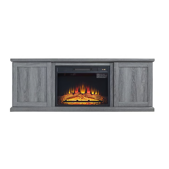
- Page 1 FIREPLACE TV STAND...
- Page 2 Table of Contents Assembly Tools Required Part Identifi cation No. 2 Phillips Screwdriver Tip Shown Actual Size Hardware Identifi cation Assembly Steps 5-19 Hammer Not actual size Page 2...
-
Page 3: Part Identification
Now you know Part Identifi cation our ABCs. ◆ While not all parts are labeled, some of the parts will have a label or an inked letter on the edge to help distinguish similar parts from each other. Use this part identification to help identify similar parts. TOP (1) ADJUSTABLE SHELF (2) BACK (2) -
Page 4: Hardware Identification
Hardware Identifi cation ◆ Screws are shown actual size. You may receive extra hardware with your unit. CAM SCREW -16 WOOD DOWEL-8 HIDDEN CAM - 16 APPLIQUE CARD- 4 METAL PIN- 12 HINGE- 4 BUMPER CARD- 1 LOWERD BLACK 2-3/8" PAN BLACK 1-3/4"... - Page 5 HOW TO USE A HIDDEN CAM & CAM SCREW OR CAM DOWEL NOTE: Various CAM SCREWS or a CAM DOWEL may be used. Turn the CAM SCREW or the surface of the part. Cam Screws Cam Dowel Push a HIDDEN CAM into the part.
- Page 6 Step 1 Assemble your unit on a carpeted floor or on the empty ◆ carton to avoid scratching your unit or the floor. Turn sixteen CAM SCREWS (1) into the TOP (A) and MOLDINGS (J and K). ◆ 16 pcs Page 6...
- Page 7 Step 2 ◆ Push sixteen HIDDEN CAMS (2) into the BACK (H), ENDS (C and D) and UPRIGHTS (E and F). ( 16pcs ) Arrow Arrow Arrow Arrow Arrow Hole The arrow in the HIDDEN CAM must point toward the Page 7...
- Page 8 Step 3 Fasten the TOP MOLDING (L) to the TOP (A). Use three BLACK 1-3/4''PAN HEAD SCREWS through ◆ the MOLDING and align to the holes in the top before you fasten. 1-3/4"BLACK PAN HEAD SCREW (3 used in this step) Page 8...
- Page 9 Step 4 Push the WOOD DOWELS (3) into the exact hole shown in ◆ the UPRIGHTS (E and F). Fasten the MOLDINGS (J and K) to the UPRIGHTS (E ◆ and F). Tighten four HIDDEN CAMS WOOD DOWEL (2 used in this step) Page 9...
- Page 10 Step 5 Fasten the UPRIGHTS (E and F) to the TOP (A). Tighten four ◆ HIDDEN CAMS. Page 10...
- Page 11 Step 6 ◆ Fasten the BACKS (H) to the TOP (A). Tighten four HIDDEN CAMS. Page 11...
- Page 12 Step 7 ◆ Fasten the ENDS (C and D) to the TOP (A). Tighten four HIDDEN CAMS. Page 12...
- Page 13 Step 8 Push the WOOD DOWELS (3) into the exact hole shown in ◆ the ENDS (C and D), BACKS (H) and UPRIGHTS (E and F). Fasten the BOTTOM (B) to the ENDS (C and D), UPRIGHTS (E and F) and the BACKS(H). ◆...
- Page 14 Step 9 Insert the METAL PINS (7) into the hole locations of your ◆ choice in the ENDS (D and C) and UPRIGHTS (F and E). Set the ADJUSTABLE SHELVES (G) onto the METAL PINS.BE is positioned as shown. ◆ Page 14...
- Page 15 Step 10 Fasten four HINGES (6) to a DOOR (N). Use eight 1/2" FLAT ◆ HEAD SCREWS (10). Repeat this step for the remaining DOOR (N). ◆ 1/2" FIAT HEAD SCREW (8 used in this step) Page 15...
- Page 16 Step 11 Before fastening the DOORS to your unit, be sure themounting screw is against the stops as shown in theright diagram. If it isn't, loosen the ◆ adjusting screw andmounting screw to slide it against the stops. Then tightenthe mounting screw. ◆...
- Page 17 Step 12 Please go to step 13 if you want to put the middle shelf (O) as show in ◆ diagram #1 or go to step 15 if you want to put the insert as show in diagram #2. Diagram #1 Diagram #2 Page 17...
- Page 18 Step 13 Insert the METAL PINS (5) into the hole locations of your ◆ choice in the UPRIGHTS (E and F). Set the ADJUSTABLE SHELF (O) onto the METAL PINS. ◆ METAL PIN (4 used in this step) Page 18...
- Page 19 Step 14 Peel APPLIQUES from the APPLIQUE CARDS (4) and stick them onto each visible HIDDEN CAM. ◆ This completes assembly. Clean with a damp cloth. Wipe dry. Apply the WARNING LABEL (11) to the TOP (A). You should be able to read the label when the TV is removed from the ◆...
- Page 20 Step 15 Fasten the BRACKETS (X and Y) to the FIREPLACE (W). Use six 3/8" FLAT HEAD ◆ SCREWS (ZZ). WARNING CAUTION!! Please read all FIREPLACE instructions prior to installing or removing it from your unit. Do not plug the FIREPLACE into the power supply until it is installed and your unit is in its 3/8"...
- Page 21 Step 16 Insert the FIREPLACE (W) in through the opening in the ◆ back of your unit. Fasten the FIREPLACE (W) to the MOLDINGS (J, K and L). Use two BLACK 3/8" PAN HEAD SCREWS (ZZ) through ◆ the BRACKETS on the FIREPLACE and into the holes in the MOLDINGS.
- Page 22 Step 17 Peel APPLIQUES from the APPLIQUE CARDS (4) and stick them onto each visible HIDDEN CAM. ◆ ◆ This completes assembly. Clean with a damp cloth. Wipe dry. Apply the WARNING LABEL (11) to the TOP (A). You should be able to read the label when the TV is removed from the ◆...
Need help?
Do you have a question about the Franklin FP3 and is the answer not in the manual?
Questions and answers