
Related Manuals for AEMC MR417


Summary of Contents for AEMC MR417
- Page 1 User Manual ENGLISH AC/DC Current Probe Models MR417 & MR527 CURRENT PROBES WITH AEMC INSTRUMENTS ®...
- Page 2 (but not limited to) physical, emotional or monetary damages due to lost revenues or lost profits that may result from the use of this documentation, whether or not the user of the documentation has been advised of the possibility of such damages. AC/DC Current Probes MR417 & MR527...
- Page 3 Serial #: Catalog #: 1200.84 / 1200.85 Model #: MR417 / MR527 Please fill in the appropriate date as indicated: Date Received: Date Calibration Due: Chauvin Arnoux , Inc. ® d.b.a AEMC Instruments ® www.aemc.com AC/DC Current Probes MR417 & MR527...
-
Page 4: Table Of Contents
4.2.2 Frequency Specifications, 1 mV/A Sensitivity ........18 4.2.3 Electrical Specifications, 10 mV/A Sensitivity........20 4.2.4 Frequency Specifications, 10 mV/A Sensitivity ........ 24 4.3 OPERATING LIMITS (MR417 AND MR527) ..........26 4.4 VARIATIONS IN THE RANGE OF USE ............ 27 4.5 POWER SUPPLY ..................28 4.6 ENVIRONMENTAL CONDITIONS ............ -
Page 5: Introduction
1. INTRODUCTION Thank you for purchasing an AEMC Instruments Current Probe Model MR417 or ® MR527. For best results from your instrument and for your safety, please read the following operating instructions carefully and comply with the precautions for use. -
Page 6: Precautions For Use
■ When handling the instrument, keep your fingers behind the physical guards. ■ Use suitable means of protection. ■ All troubleshooting and metrological checks must be performed by competent and accredited personnel. AC/DC Current Probes MR417 & MR527... -
Page 7: Receiving Your Shipment
Save the damaged packing container to substantiate your claim. 1.3 ORDERING INFORMATION AC/DC Current Probe Model MR417 ........... Cat. #1200.84 Includes 9 V battery, multi-language safety data sheet, and user manual AC/DC Current Probe Model MR527 ........... Cat. #1200.85 Includes 9 V battery, multi-language safety data sheet, and user manual 1.3.1 Replacement Parts/Accessories... -
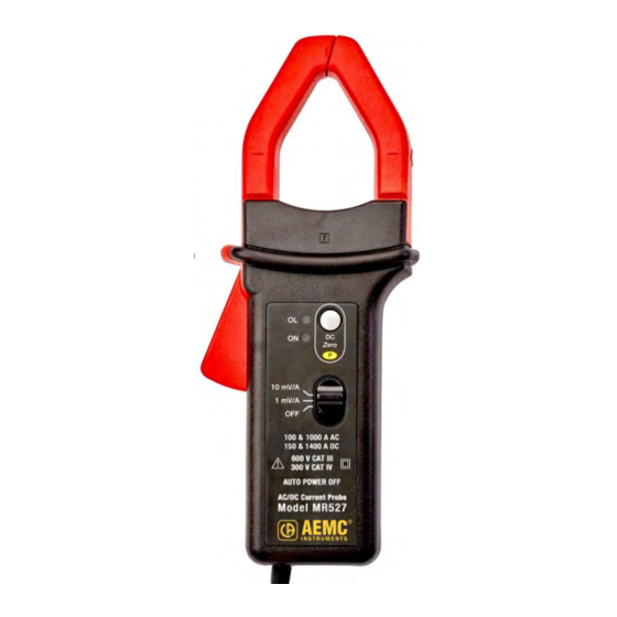
Page 8: Description
2. DESCRIPTION The Models MR417 and MR527 are clamp-on current probes that measure DC currents up to 1400 A, AC currents up to 1000 Arms (1400 A peak), and combined AC+DC currents without opening the circuit that the current is flowing through. They indicate the shape and amplitude of the current measured in the form of a voltage. -
Page 9: Interface
P (Permanent mode) indicator. Holding down the DC Zero button while turning ON the instrument enables Permanent mode. In this mode, Auto Standby is disabled (see § 3.4). 3-position slide switch USB port Trigger Hand guard Mobile jaw AC/DC Current Probes MR417 & MR527... -
Page 10: Mr527
P (Permanent mode) indicator. Holding down the DC Zero button while turning ON the instrument enables Permanent mode. In this mode, Auto Standby is disabled (see § 3.4). 3-position slide switch USB port Trigger Hand guard Mobile jaw AC/DC Current Probes MR417 & MR527... -
Page 11: Operation
When operating on external power, the Auto Standby feature is disabled. The color of the ON indicator shows whether the automatic standby is enabled (green) or disabled (yellow). AC/DC Current Probes MR417 & MR527... -
Page 12: Turning The Instrument On
■ Press the DC Zero button again. ■ In the event of failure, or if the clamp is switched off (selector set to OFF), it is the last adjustment of the DC Zero that is kept. AC/DC Current Probes MR417 & MR527... -
Page 13: Measurements
Figure 4 (MR527 shown) 3.6.2 Converting to Current The MR417 and MR527 both provide two measurement ranges. The MR417 measures current up to 600 A with 1 mV of output corresponding to 1 A and measures current up to 60 A with 10 mV corresponding to 1 A. The MR527 measures current up to 1400 A with 1 mV corresponding to 1 A and measures current up to 150 A with 10 mV corresponding to 1 A. -
Page 14: Specifications
(3 to 300) Aac (300 to 400) Aac Phase shift ≤ -2.2 ° ≤ -1.5 ° MR527 Specified Measurement Range (3 to 200) Aac (200 to 1000) Aac Phase shift ≤ -2 ° ≤ -1.5 ° AC/DC Current Probes MR417 & MR527... - Page 15 Typical amplitude error curve at 60 Hz MR417 Error (%) Current (A) MR527 Error (%) Current (A) AC/DC Current Probes MR417 & MR527...
- Page 16 Typical amplitude error curve in DC MR417 Error (%) 1000 Current (A) MR527 Error (%) 1000 10000 Current (A) AC/DC Current Probes MR417 & MR527...
- Page 17 Typical phase error curve at 60 Hz MR417 Phase shift (°) Current (A) MR527 Phase shift (°) Current (A) AC/DC Current Probes MR417 & MR527...
-
Page 18: Frequency Specifications, 1 Mv/A Sensitivity
MR417: 2.8 mΩ <0.01 mΩ impedance MR527: 0.05 mΩ MR527: 0.14 mΩ MR527: 3.4 mΩ Typical amplitude error versus frequency curve at 60 A MR417 Error (%) Frequency (Hz) MR527 Error (%) Frequency (Hz) AC/DC Current Probes MR417 & MR527... - Page 19 Typical phase versus frequency error curve at 60 A MR417 Phase shift (°) 0° -10° -20° -30° -40° -50° -60° 1000 10000 100000 Frequency (Hz) MR527 Phase shift (°) 0° -10° -20° -30° -40° -50° -60° 1000 10000 100000 Frequency (Hz) AC/DC Current Probes MR417 & MR527...
-
Page 20: Electrical Specifications, 10 Mv/A Sensitivity
Phase error (45 to 65) Hz MR417 Specified measurement range (1 to 20) Aac (20 to 40) Aac Phase shift ≤ -3 ° ≤ -2.2 ° MR527 Specified measurement range (1 to 100) Aac Phase shift ≤ -2 ° AC/DC Current Probes MR417 & MR527... - Page 21 Typical amplitude error vs current curve at 60 Hz MR417 Error (%) Current (A) MR527 Error (%) Current (A) AC/DC Current Probes MR417 & MR527...
- Page 22 Typical amplitude error vs current curve in DC MR417 Error (%) Current (A) MR527 Error (%) Current (A) AC/DC Current Probes MR417 & MR527...
- Page 23 Typical phase vs current error curve at 60 Hz MR417 Phase shift (°) Current (A) MR527 Phase shift (°) Current (A) AC/DC Current Probes MR417 & MR527...
-
Page 24: Frequency Specifications, 10 Mv/A Sensitivity
MR417: 2.8 mΩ <0.01 mΩ impedence MR527: 0.05 mΩ MR527: 0.14 mΩ MR527: 3.4 mΩ Typical amplitude error versus frequency curve at 30 A MR417 Error (%) Frequency (Hz) MR527 Error (%) Frequency (Hz) AC/DC Current Probes MR417 & MR527... - Page 25 Typical phase versus frequency error curve at 100 A MR417 Phase shift (°) 0° -10° -20° -30° -40° -50° -60° 1000 10000 100000 Frequency (Hz) MR527 Phase shift (°) 0° -10° -20° -30° -40° -50° -60° 1000 10000 100000 Frequency (Hz) AC/DC Current Probes MR417 & MR527...
-
Page 26: Operating Limits (Mr417 And Mr527)
Fall time (from 90 to 10) %: ≤ 11 μs AC noise on output: ≤ 3 mV or 0.3 A Delay time at 10 %: ≤ 10 μs Square wave response curves 4.3 OPERATING LIMITS (MR417 AND MR527) • In DC: 3000 A permanent •... -
Page 27: Variations In The Range Of Use
600 Adc: 5.5 A 800 Adc: 5.8 A Remanence MR527: 100 Adc: 2.8 A 200 Adc: 3.5 A 400 Adc: 5 A 800 Adc: 5.3 A 1200 Adc: 5.7 A 1400 Adc: 5.8 A AC/DC Current Probes MR417 & MR527... -
Page 28: Power Supply
°C °C 1 = Range of reference 2 = Operating range 3 = Storage range Indoor use Degree of pollution: 2 Altitude: < 6500 ft (2000 m) Transport altitude: ≤ 40,000 ft (12,000 m) AC/DC Current Probes MR417 & MR527... -
Page 29: Mechanical Specifications
Cables: One 1.18 in (30 mm) or two 0.94 in (24 mm) Bus Bar: One 1.97 x 0.39 in (50 x 10 mm) or two 1.23 x 0.39 in (31.5 x 10 mm) or three 0.98 x 0.31 in (25 x 8 mm) Figure 5 AC/DC Current Probes MR417 & MR527... - Page 30 Bus Bar: One 1.97 x 0.49 in (50 x 12.5 mm) or two 0.98 x 0.2 in (25 x 5 mm); 1.24 x 0.30 in (31.5 x 10 mm) or three 0.98 x 0.31 in (25 x 8 mm) Figure 6 AC/DC Current Probes MR417 & MR527...
-
Page 31: Housing Protection
Category IV and 600 V Category III. Double or reinforced insulation Type of current sensor per IEC/EN 61010-2-032 or BS EN 61010-2-032: type A Electromagnetic Compatibility: The device is in conformity with standard IEC/EN 61326-1 or BS EN 61326-1. AC/DC Current Probes MR417 & MR527... -
Page 32: Maintenance
4. Insert the replacement battery into the snap-in battery connector and place it into the battery compartment. 5. Replace the battery compartment cover. NOTE: Depleted batteries must not be treated as ordinary household waste. Take them to the appropriate collection point for recycling. AC/DC Current Probes MR417 & MR527... -
Page 33: Repair And Calibration
Chauvin Arnoux , Inc. d.b.a. AEMC Instruments ® ® Phone: (800) 343-1391 (Ext. 351) Fax: (603) 742-2346 techsupport@aemc.com E-mail: www.aemc.com AC/DC Current Probes MR417 & MR527... -
Page 34: Limited Warranty
Instruments, not by the distributor from whom it was purchased. This ® warranty is void if the unit has been tampered with, abused, or if the defect is related to service not performed by AEMC Instruments. ® Full warranty coverage and product registration is available on our web- site at www.aemc.com/warranty.html... - Page 35 NOTES:...
- Page 36 03/23 99-MAN 100522 v07 AEMC Instruments ® 15 Faraday Drive • Dover, NH 03820 USA Phone: (603) 749-6434 • (800) 343-1391 • Fax: (603) 742-2346 www.aemc.com © Chauvin Arnoux , Inc. d.b.a. AEMC Instruments. All Rights Reserved. ® ®...
Need help?
Do you have a question about the MR417 and is the answer not in the manual?
Questions and answers