Table of Contents
Advertisement
Quick Links
Advertisement
Table of Contents

Related Manuals for AEMC MR417


Summary of Contents for AEMC MR417
- Page 1 MR417 ■ AC/DC CURRENT PROBE MR527 ENGLISH User Manual...
- Page 2 Serial #: 1200.84 / 1200.85 Catalog #: MR417 / MR527 Model #: Please fill in the appropriate date as indicated: Date Received: Date Calibration Due: ® Chauvin Arnoux , Inc. ® d.b.a AEMC Instruments www.aemc.com Current Probe Models MR417/MR527...
-
Page 3: Table Of Contents
CONTENTS 1 DESCRIPTION……..................7 1.1 Interface ........................8 1.1.1 MR417 ....................8 1.1.2 MR527 ....................9 2 OPERATION ....................10 2.1 Battery Installation ....................10 2.2 External Power (Optional)..................10 2.3 Turning ON the Instrument .................. 11 2.4 Auto Standby ......................11 2.5 DC Zero Adjustment .................... - Page 4 Thank you for purchasing the Current Probe Model MR417 or MR527. For best results from your instrument and for your safety, read the following operating instructions carefully and comply with the precautions for use. This instrument is compliant with the IEC 61010-2-032 safety standard for voltages of 300V with respect to earth in measurement category IV, or 600V in category III.
- Page 5 When handling the instrument, keep your fingers behind the physical guards. Use suitable means of protection. All troubleshooting and metrological checks must be performed by competent and accredited personnel. Current Probe Models MR417/MR527...
- Page 6 Save the damaged packing container to substantiate your claim. Ordering Information AC/DC Current Probe Model MR417 ........... Cat. #1200.84 Includes 9V battery, multi-language safety data sheet and user manual AC/DC Current Probe Model MR527 ........... Cat. #1200.85...
-
Page 7: Description
1 DESCRIPTION The Models MR417 and MR527 are clamp-on current probes that measure DC currents up to 1400A, AC currents up to 1000A (1400A peak), and combined AC+DC currents without opening the circuit in which the currents flow. They indicate the shape and amplitude of the current measured in the form of a voltage. -
Page 8: Interface
Arrow indicating current flow direction Male BNC connector DC Zero button OL (overload) and ON indicators. ON is green when Auto Standby is enabled, yellow when it disabled. 3-position slide switch USB port Trigger Hand guard Mobile jaw Current Probe Models MR417/MR527... -
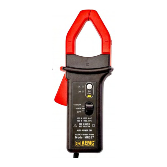
Page 9: Mr527
Arrow indicating current flow direction Male BNC connector DC Zero button OL (overload) and ON indicators. ON is green when Auto Standby is enabled, yellow when it disabled. 3-position slide switch USB port Trigger Hand guard Mobile jaw Current Probe Models MR417/MR527... -
Page 10: Operation
When operating on external power, the Auto Standby feature is disabled. The color of the ON indicator shows whether automatic standby is enabled (green) or disabled (yellow). Current Probe Models MR417/MR527... -
Page 11: Turning On The Instrument
In this case, ensure the clamp is not on a conductor and that its jaws are correctly closed. Then press DC Zero again. Alternately, turn the clamp OFF and then back ON. The previous zero adjustment will remain in effect. Current Probe Models MR417/MR527... -
Page 12: Measurements
Figure 4 (MR527 shown) 2.6.2 Converting to Current The MR417 and MR527 both provide two measurement ranges. The MR417 measures current up to 600A with 1mV of output corresponding to 1A, and current up to 60A with 10mV corresponding to 1A. The MR527 measures current up to 1400A with 1mV corresponding to 1A, and current up to 150A with 10mV corresponding to 1A. -
Page 13: Specifications
Phase error (45 to 65Hz) MR417 Specified Measurement range 3 to 300A 300 to 400A Phase shift ≤ -2.2° ≤ -1.5° MR527 Specified Measurement range 3 to 200A 200 to 1000A Phase shift ≤ -2° ≤ -1.5° Current Probe Models MR417/MR527... - Page 14 Typical amplitude error curve at 60Hz MR417 Error (%) Current (A) MR527 Error (%) Current (A) Current Probe Models MR417/MR527...
- Page 15 Typical amplitude error curve in DC MR417 Error (%) Current (A) MR527 Error (%) Current (A) Current Probe Models MR417/MR527...
- Page 16 Typical phase error curve at 60Hz MR417 Phase shift (°) Current (A) MR527 Phase shift (°) Current (A) Current Probe Models MR417/MR527...
-
Page 17: Frequency Specifications, 1Mv/A Sensitivity
400Hz 1kHz 10kHz MR417: 0.01mΩ MR417: 0.12mΩ Insertion MR417: 2.8mΩ <0.01mΩ impedance MR527: 3.4mΩ MR527: 0.05mΩ MR527: 0.14mΩ Typical amplitude error versus frequency curve at 100A MR417 Error (%) Frequency (Hz) MR527 Error (%) Frequency (Hz) Current Probe Models MR417/MR527... - Page 18 Typical phase versus frequency error curve at 100A MR417 Phase shift (°) Frequency (Hz) MR527 Phase shift (°) Frequency (Hz) Current Probe Models MR417/MR527...
-
Page 19: Electrical Specifications, 10Mv/A Sensitivity
≤±1.5% R ≤±1.5% R Phase error (45 to 65Hz) MR417 Specified Measurement range 1 to 20A 20 to 40A Phase shift ≤ -3° ≤ -2.2° MR527 Specified Measurement range 1 to 100A Phase shift ≤ -2° Current Probe Models MR417/MR527... - Page 20 Typical amplitude error vs current curve at 60Hz MR417 Error (%) Current (A) MR527 Error (%) Current (A) Current Probe Models MR417/MR527...
- Page 21 Typical amplitude error vs current curve in DC MR417 Error (%) Current (A) MR527 Error (%) Current (A) Current Probe Models MR417/MR527...
- Page 22 Typical phase vs current error curve at 60Hz MR417 P hase shift (°) Current (A) MR527 Phase shift (°) Current (A) Current Probe Models MR417/MR527...
-
Page 23: Frequency Specifications, 10Mv/A Sensitivity
400Hz 1kHz 10kHz MR417: 0.01mΩ MR417: 0.12mΩ MR417: 2.8mΩ Insertion <0.01mΩ impedance MR527: 0.05mΩ MR527: 0.14mΩ MR527: 3.4mΩ Typical amplitude error versus frequency curve at 100A MR417 Error (%) Frequency (Hz) MR527 Error (%) Frequency (Hz) Current Probe Models MR417/MR527... - Page 24 Typical phase versus frequency error curve at 100A MR417 Phase shift (°) Frequency (Hz) MR527 Phase shift (°) Frequency (Hz) Current Probe Models MR417/MR527...
-
Page 25: Operating Limits
In AC: 1000A permanent up to 1kHz from 1kHz, I = 1000/f (kHz) Conductor temperature: ≤ 194°F (90°C), 230°F (110°C) peak Temperature of the jaws: ≤ 176°F (80°C) Curve of derating versus frequency Current (A) Frequency (kHz) Current Probe Models MR417/MR527... -
Page 26: Variations In The Range Of Use
The instrument is powered by a 9V battery (type 6LR61, 6LF22, or NEDA 1604). The average battery life is 50 hours with an alkaline battery. The instrument can also be powered by an external supply (5V , 100mA) via the type B micro‑USB connector. Current Probe Models MR417/MR527... -
Page 27: Environmental Conditions
The instrument must be used in the following environmental conditions. °C 1 = Range of reference 2 = Operating range 3 = Storage range Indoor use Degree of pollution: 2 Altitude: < 6500’ (2000m) Transport altitude: ≤ 40,000’ (12,000m) Current Probe Models MR417/MR527... -
Page 28: Mechanical Specifications
Maximum Conductor Size: Cables: One 1.18” (30mm) or two 0.94” (24mm) Bus Bar: One 1.97 x 0.39” (50 x 10mm) or two 1.23 x 0.39” (31.5 x 10mm) or three 0.98” x 0.31” (25 x 8mm) Figure 5 Current Probe Models MR417/MR527... - Page 29 Cables: One 1.5” (39mm) or two 1” (25.4mm) Bus Bar: One 1.97 x 0.49” (50 x 12.5mm) or two 0.98 x 0.2” (25 x 5mm); 1.24” x 0.30” (31.5 x 10mm) or three 0.98” x 0.31” (25 x 8mm) Figure 6 Current Probe Models MR417/MR527...
-
Page 30: Housing Protection
The instrument is compliant with IEC 61010-2-032, 300V in CAT IV or 600V in CAT III. Double or reinforced insulation Type of current sensor per IEC 61010-2-032: type A 3.9 Electromagnetic Compatibility The device is in conformity with standard IEC 61326-1. Current Probe Models MR417/MR527... -
Page 31: Maintenance
4. Insert the replacement battery into the snap-in battery connector, and place it into the battery compartment. 5. Replace the battery compartment cover. Spent batteries must not be treated as ordinary household waste. Take them to the appropriate collection point for recycling. Current Probe Models MR417/MR527... -
Page 32: Repair And Calibration
® ® Chauvin Arnoux , Inc. d.b.a. AEMC Instruments 200 Foxborough Boulevard Foxborough, MA 02035, USA Phone: (800) 343-1391 (508) 698-2115 Fax: (508) 698-2118 techsupport@aemc.com www.aemc.com NOTE: Do not ship instruments to our Foxborough, MA address. Current Probe Models MR417/MR527... -
Page 33: Limited Warranty
® Instruments. related to service not performed by AEMC Full warranty coverage and product registration is available on our website at www.aemc.com/warranty.html. Please print the online Warranty Coverage Information for your records. - Page 34 NOTES Current Probe Models MR417/MR527...
- Page 35 NOTES Current Probe Models MR417/MR527...
- Page 36 03/20 99-MAN 100522 v2 Chauvin Arnoux ® , Inc. d.b.a. AEMC ® Instruments 15 Faraday Drive • Dover, NH 03820 USA Phone: (603) 749-6434 • Fax: (603) 742-2346 www.aemc.com...
Need help?
Do you have a question about the MR417 and is the answer not in the manual?
Questions and answers