Table of Contents
Advertisement
Available languages
Available languages
Quick Links
Advertisement
Chapters
Table of Contents

Related Manuals for Stahl isbus 9419/08 Series


Summary of Contents for Stahl isbus 9419/08 Series
- Page 1 Betriebsanleitung/Operating Instructions Feldbus Power Supply System Fieldbus Power Supply System > 9412/00-310 Feldbus Power Supply > 9419/08... bus-Träger > 9412/00-310 Fieldbus Power Supply > 9419/08... bus-Carrier...
- Page 3 Betriebsanleitung Feldbus Power Supply System > 9412/00-310 Feldbus Power Supply > 9419/08... bus-Träger...
-
Page 4: Table Of Contents
Inhaltsverzeichnis Inhaltsverzeichnis Inhaltsverzeichnis ....................2 Allgemeine Angaben .....................3 Hersteller .......................3 Angaben zur Betriebsanleitung ................3 Begriffsbestimmungen ...................3 Verwendete Symbole ....................4 Allgemeine Sicherheitshinweise ................4 Sicherheitshinweise für Montage- und Bedienpersonal ........4 Warnhinweise ......................5 Normenkonformität ....................5 Vorgesehener Einsatzbereich ................6 Technische Daten ....................7 Maximal zulässige Umgebungstemperaturen (ohne Zwangsbelüftung) .....10 Waagerechte Einbaulage mit Abstand ..............10 Senkrechte Einbaulage mit Abstand ..............11 Waagerechte Einbaulage ohne Abstand .............12... -
Page 5: Allgemeine Angaben
Allgemeine Angaben Allgemeine Angaben 2.1 Hersteller R. STAHL Schaltgeräte GmbH Am Bahnhof 30 74638 Waldenburg, Germany Telefon: +49 7942 943-0 Telefax: +49 7942 943-4333 Internet: www.stahl.de 2.2 Angaben zur Betriebsanleitung ID-NR.: 200744 / 941260310030 Publikationsnummer: S-BA-9412-01-de-02/09/2009 Hardwareversion: Softwareversion: 01-00 Technische Änderungen vorbehalten. -
Page 6: Verwendete Symbole
Allgemeine Sicherheitshinweise Redundanz Das Segment und der Host können redundant versorgt werden. Hierfür werden zwei Feldbus Power Supplies gemeinsam angeschlossen. 2.4 Verwendete Symbole Handlungsaufforderung: Beschreibt durch den Anwender auszuführende Tätigkeiten. Reaktionszeichen: Beschreibt Resultate bzw. Reaktionen auf Tätigkeiten. Aufzählungszeichen Hinweiszeichen: Beschreibt Hinweise und Empfehlungen. Warnzeichen: Gefahr durch explosionsfähige Atmosphäre! Allgemeine Sicherheitshinweise... -
Page 7: Warnhinweise
Allgemeine Sicherheitshinweise Bei Betrieb der Geräte: Betriebsanleitung am Einsatzort verfügbar halten. Sicherheitshinweise beachten. Nationale Sicherheits- und Unfallverhütungsvorschriften beachten. Gerät nur entsprechend der Leistungsdaten betreiben. Wartungsarbeiten bzw. Reparaturen, die nicht in der Betriebsanleitung beschrieben sind, dürfen nicht ohne vorherige Abstimmung mit dem Hersteller durchgeführt werden. -
Page 8: Vorgesehener Einsatzbereich
Vorgesehener Einsatzbereich Vorgesehener Einsatzbereich Die Feldbus Power Supply dient zur Versorgung eines FOUNDATION™ fieldbus H1 Segments. Sie versorgt die angeschlossenen Feldgeräte und den Host mit Energie. Die Versorgung des Segments kann wahlweise einfach, redundant oder parallel (Boost-Betrieb) erfolgen. Redundanz-Betrieb Bei redundanter Speisung versorgen zwei Feldbus Power Supplies ein Segment parallel. Bei Ausfall einer Feldbus Power Supply übernimmt die andere Feldbus Power Supply automatisch die Speisung und es erfolgt eine Fehlermeldung über einen Relaiskontakt. -
Page 9: Technische Daten
Technische Daten Technische Daten Ausführung 9412/00-310 Explosionsschutz Gasexplosionsschutz ATEX E II 3G Ex nAc nCc II T4 IECEx Ex nAc nCc II T4 Installation Zone 2, sicherer Bereich Bescheinigungen ATEX BVS 09 ATEX E 099 X IECEx IECEx BVS 09.0043X Hilfsenergie Nennspannung 24 V DC... - Page 10 Technische Daten Mechanische Daten Schraubklemmen Anschluss einadrig - starr 0,2 mm ... 2,5 mm - flexibel 0,2 mm ... 2,5 mm - flexibel mit Aderendhülsen 0,25 mm ... 2,5 mm (ohne / mit Kunststoffhülse) Anschluss zweiadrig - starr 0,2 mm ...
- Page 11 Technische Daten Maßzeichnung (alle Maße in mm) - Änderungen vorbehalten Maß X 17,6 Schraubklemmen 108 mm Federzugklemmen 128 mm 09685E00 Feldbus Power Supply 9412/00-3.0-11 12621E00 Feldbus Power Supply auf bus-Träger 9419/08.-XX0-..C1 12622E00 bus-Träger 9419/08.-XX0-..C1 200744 / 941260310030 Feldbus Power Supply System S-BA-9412-01-de-02/09/2009 9412/00-310, 9419/08...
-
Page 12: Maximal Zulässige Umgebungstemperaturen (Ohne Zwangsbelüftung)
Maximal zulässige Umgebungstemperaturen (ohne Zwangsbelüftung) Maximal zulässige Umgebungstemperaturen (ohne Zwangsbelüftung) In Abhängigkeit des Einbaus ergibt sich für den Ausgangsstrom einer Feldbus Power Supply I eine maximale Umgebungstemperatur T Für die unterschiedlichen Einbauvarianten muss aus dem entsprechenden Diagramm die maximale Umgebungstemperatur an den Geräten ermittelt werden. Der Strom I entspricht dem Ausgangsstrom einer Feldbus Power Supply: Beim Singlebetrieb wird ein Segment von einer Feldbus Power Supply mit Energie... -
Page 13: Senkrechte Einbaulage Mit Abstand
Maximal zulässige Umgebungstemperaturen (ohne Zwangsbelüftung) 6.2 Senkrechte Einbaulage mit Abstand 12588E00 12589E00 12582E00 200744 / 941260310030 Feldbus Power Supply System S-BA-9412-01-de-02/09/2009 9412/00-310, 9419/08... -
Page 14: Waagerechte Einbaulage Ohne Abstand
Maximal zulässige Umgebungstemperaturen (ohne Zwangsbelüftung) 6.3 Waagerechte Einbaulage ohne Abstand 12579E00 12584E00 12587E00 Feldbus Power Supply System 200744 / 941260310030 9412/00-310, 9419/08... S-BA-9412-01-de-02/09/2009... -
Page 15: Senkrechte Einbaulage Ohne Abstand
Maximal zulässige Umgebungstemperaturen (ohne Zwangsbelüftung) 6.4 Senkrechte Einbaulage ohne Abstand 12590E00 12591E00 12583E00 200744 / 941260310030 Feldbus Power Supply System S-BA-9412-01-de-02/09/2009 9412/00-310, 9419/08... -
Page 16: Hauptkomponenten
Hauptkomponenten Hauptkomponenten 7.1 Hauptkomponenten der Feldbus Power Supply 12574E00 Komponente Funktion Anschlussklemmen Anschluss für die Hilfsenergie und die Redundanzverschaltung (siehe Kapitel „Installation“) Diagnoseschnittstelle Auslesen der Diagnoseinformationen (nur bei Advanced Feldbus Power Supply) LED „PWR“, grün Anzeige für den Status der Hilfsenergie (siehe Kapitel „LEDs an der Feldbus Power Supply“) LED „ERR“, rot Anzeige für den Status des Gerätes... -
Page 17: Dip-Schalter An Der Feldbus Power Supply
Hauptkomponenten 7.2 DIP-Schalter an der Feldbus Power Supply Übersicht der DIP-Schalter an der Feldbus Power Supply siehe Kapitel „Hauptkomponenten der Feldbus Power Supply“. DIP-Schalter „TERM“ - Terminator Bei der Auslieferung ist der interne Terminator aktiviert. Beim Redundanz- oder Boost-Betrieb zweier Feldbus Power Supplies muss der Terminator bei beiden Feldbus Power Supplies die gleiche Einstellung (ON oder OFF) haben. - Page 18 Spannungsabfälle auf den Leitungen oder an den Komponenten auf. Vor Aktivierung des Boost-Betriebs, Segment mit dem Feldbus Wizard der Firma R. STAHL (siehe Kapitel „Zubehör und Ersatzteile“) prüfen. Im Boost-Betrieb kann keine redundanten Einspeisung erfolgen bzw. bei Redundanz-Betrieb kann keine Stromerhöhung erfolgen.
-
Page 19: Leds Und Fehlermeldekontakt An Der Feldbus Power Supply
Hauptkomponenten 7.3 LEDs und Fehlermeldekontakt an der Feldbus Power Supply Für eine Übersicht der LEDs an der Feldbus Power Supply siehe Kapitel „Hauptkomponenten der Feldbus Power Supply“. Farbe Zustand Beschreibung/Fehlerursache Fehlerbehebung Meldung Relaiskontakt grün externe Hilfsenergie vorhanden „PWR“ Hilfsenergie ausgefallen Hilfsenergieversorgung kontrollieren Hilfsenergieversorgung ist verpolt korrekten Anschluss der Hilfsenergie... -
Page 20: Hauptkomponenten Des Bus-Trägers
Hauptkomponenten 7.4 Hauptkomponenten des bus-Trägers 12575E00 Komponente Funktion bus-Träger Aufnahme für 8 Feldbus Power Supplies, Anschlussmöglichkeiten für die externe Hilfsenergie, die Trunks, die Hosts und die Diagnosemeldungen pac-Bus Übertragung der externe Hilfsenergie an die einzelnen Feldbus Power Supplies Feldbus Power Supply Versorgung von Host und Trunk mit Energie Anschlussklemmen (variantenabhängige Ausführung mit Anschluss für Host und Trunk... -
Page 21: Dip-Schalter Am Bus-Träger
Hauptkomponenten 7.5 DIP-Schalter am bus-Träger WARNUNG Explosionsgefahr! Tod oder schwerste Verletzungen! Ändern der DIP-Schalter in Zone 2 unter Spannung ist nicht zulässig! Übersicht der DIP-Schalter am bus-Träger siehe Kapitel „Hauptkomponenten des bus-Trägers“. DIP-Schalter „PWR“ - Redundante Hilfsenergie Bei der Auslieferung ist die redundante Hilfsenergie aktiviert. einfache redundante Hilfsenergie... -
Page 22: Montage
Montage Montage 8.1 Feldbus Power Supply auf DIN-Schiene mit und ohne pac-Bus montieren Montage des pac-Bus Die Komponenten für den pac-Bus müssen separat bestellt werden. (siehe Kapitel „Ersatzteile und Zubehör“) Bei 24 V Hilfsenergie sind maximal 8 pac-Bus Elemente möglich. 07392E00 Gewünschte Anzahl der pac-Bus-Elemente zusammenschieben. - Page 23 Montage Montage der Feldbus Power Supplies Beim Aufschwenken des Geräts auf die DIN-Schiene darauf achten, dass es nicht verkantet. 06885E00 Gerät auf DIN-Schiene korrekt aufsetzen (1). Gerät auf DIN-Schiene aufschwenken (2). Demontage der Feldbus Power Supplies 06881E00 Fußriegel (1) mit dem Schraubendreher etwas herausziehen. Gerät herausschwenken.
-
Page 24: Feldbus Power Supply Auf Bus-Träger Montieren
Montage 8.2 Feldbus Power Supply auf bus-Träger montieren Der bus-Träger kann auf einer Montageplatte oder auf einer DIN-Schiene entsprechend EN 50022 Typ NS35/7,5 oder NS35/15 montiert werden. bus-Träger auf Montageplatte montieren 08037E00 Gerät auf Montageplatte aufsetzen (Montagemaße siehe Maßzeichnungen). Gerät mit Schrauben auf Montageplatte befestigen. bus-Träger auf DIN-Schiene montieren 12623E00 Gerät auf DIN-Schiene korrekt aufsetzen. - Page 25 Montage Montage Feldbus Power Supply im bus-Träger Vor der Montage der Feldbus Power Supply müssen alle Klemmen auf der Seite des Fußriegels entfernt werden. 06883E00 Schraubendreher hinter schwarzer und grüner Klemme ansetzen (1). Alle Klemmen herausdrücken (2). 06887E00 Gerät auf bus-Träger korrekt ansetzen und vollständig einschwenken. Sicherstellen, dass der rote Rasthebel in die Aussparung der Feldbus Power Supply greift.
-
Page 26: Installation
Installation Demontage der Feldbus Power Supply aus dem bus-Träger 06884E00 Schraubendreher in den roten Rasthebel stecken (1) und Rasthebel mit einer Schwenkbewegung öffnen. Gerät wird aus dem Steckplatz geschoben (2). Gerät herausnehmen. Installation WARNUNG Nicht korrekt installierte Komponenten! Bei nicht korrekt installierten Komponenten in der Zone 2 ist der Explosionsschutz nicht mehr gewährleistet. -
Page 27: Feldbus Power Supply Im Simplex-Betrieb Auf Din-Schiene Mit Und Ohne Pac-Bus Installieren
Installation 9.2 Feldbus Power Supply im Simplex-Betrieb auf DIN-Schiene mit und ohne pac-Bus installieren pac-bus 24 V Diag 24 V DC Diag Red. 2 Host Red. 1 bus-carrier Trunk 12573E00 Typ 9412/00-310-11 Hilfsenergie ohne pac-Bus anschließen Hilfsenergie an die grünen Klemmen 7 (+) und 9 (-) der Feldbus Power Supply anschließen. -
Page 28: Feldbus Power Supply Im Redundanz-Betrieb Bzw. Boost-Betrieb Auf Din-Schiene Mit Und Ohne Pac-Bus Installieren
Installation 9.3 Feldbus Power Supply im Redundanz-Betrieb bzw. Boost-Betrieb auf DIN-Schiene mit und ohne pac-Bus installieren Die Verdrahtung der Trunk- und Hostanschlüsse im Redundanz-Betrieb kann über externe Klemmen oder durch Auflegen von zwei Leitern auf einer Klemme direkt an der Feldbus Power Supply erfolgen. Die maximalen Anschluss-querschnitte siehe Kapitel „Technische Daten“. - Page 29 Installation Hilfsenergie ohne pac-Bus anschließen Hilfsenergie an die grünen Klemmen 7 (+) und 9 (-) der Feldbus Power Supply 1 und 2 anschließen. Hilfsenergie mit pac-Bus anschließen Hilfsenergie an die Klemmen 1 (+) und 2 (-) des pac-Bus anschließen. Fehlerkontakt ohne pac-Bus anschließen Fehlerkontakt an die grünen Klemmen 8 (+) und 9 (-) der Feldbus Power Supply 1 und 2 anschließen.
-
Page 30: Feldbus Power Supply Im Simplex-Betrieb Auf Bus-Träger Installieren
Installation 9.4 Feldbus Power Supply im Simplex-Betrieb auf bus-Träger installieren Im Simplex-Betrieb versorgt jede Feldbus Power Supply ein Segment. Damit können je bus-Träger bis zu acht Segmente angeschlossen werden. 12576E00 Typ 9419/08F-XX0-..Hilfsenergie anschließen (nicht redundant) Die Hilfsenergie an die Klemmen 2 (+) und 3 (-) anschließen. DIP-Schalter „PWR“... - Page 31 Installation Anschlusskabel abisolieren Die Zugentlastung und Schirmauflage der Feldbus-Anschlusskabel wird durch das Festklemmen unter die Schirmschiene hergestellt (max. Anzugsdrehmoment: 0,7 Nm). 12578E00 Anschlusskabel (1) gemäß Zeichnung abisolieren. Freigelegten Schirm (2) gemäß Zeichnung zurückklappen. Sicherstellen, dass der Kabeldurchmesser mit dem umgeklappten Schirm die angegebenen Maße nicht überschreitet.
-
Page 32: Feldbus Power Supply Im Redundanz-Betrieb Bzw. Boost-Betrieb Auf Bus-Träger Installieren
Installation 9.5 Feldbus Power Supply im Redundanz-Betrieb bzw. Boost-Betrieb auf bus-Träger installieren Der Redundanz- und Boost-Betrieb der Feldbus Power Supplies auf dem bus-Träger ist nur mit den bus-Trägern vom Typ 9419/08R möglich. Im Redundanz-Betrieb versorgen jeweils zwei benachbarte Feldbus Power Supplies ein Segment redundant. - Page 33 Installation Anschlusskabel abisolieren Die Zugentlastung und Schirmauflage der Feldbus-Anschlusskabel wird durch das Festklemmen unter die Schirmschiene hergestellt (max. Anzugsdrehmoment: 0,7 Nm). 12578E00 Anschlusskabel (1) gemäß Zeichnung abisolieren. Freigelegten Schirm (2) gemäß Zeichnung zurückklappen. Sicherstellen, dass der Kabeldurchmesser mit dem umgeklappten Schirm die angegebenen Maße nicht überschreitet.
-
Page 34: Inbetriebnahme
WARNUNG Gefahr durch unsachgemäße Wartung/Reparatur Explosionsschutz ist nicht mehr gewährleistet. Reparaturen am Gerät dürfen nur von R. STAHL durchgeführt werden. Reparaturarbeiten dürfen nur vom Hersteller durchgeführt werden. Umbauten oder Änderungen am Betriebsmittel sind nicht gestattet. Betriebsmittel an den Hersteller zur Reparatur zurücksenden. -
Page 35: Zubehör Und Ersatzteile
Zubehör und Ersatzteile 14 Zubehör und Ersatzteile Benennung Abbildung Beschreibung Bestellnummer Gewicht Beschriftungsbogen 180 Schilder 160640 0.001 DIN A4 09900E00 Schraubklemmen grün 112817 0.001 07099E00 schwarz 112816 0.001 07093E00 Schraubklemmen mit schwarz 113005 0.001 Prüfabgriff 07108E00 Federzugklemmen grün 112825 0.005 07094E00 schwarz 112824... - Page 36 Zubehör und Ersatzteile Benennung Abbildung Beschreibung Bestellnummer Gewicht Feldbus Wizard Engineering Tool zum Projektieren von Fieldbus – – Engineering Engineering Tool Foundation oder Profibus PA Feldbus-Segmenten Tool Download unter www.fieldbus-solutions.info 07376E00 Abschlusswiderstand Feldbus Terminator "Ex m" 9418/01-201-10 0.080 06501E00 Feldbus Terminator "Ex i" 9418/02-201-10 0.080 06501E00...
-
Page 37: Eg-Baumusterprüfbescheinigung (1. Seite)
EG-Baumusterprüfbescheinigung (1. Seite) 15 EG-Baumusterprüfbescheinigung (1. Seite) 200744 / 941260310030 Feldbus Power Supply System S-BA-9412-01-de-02/09/2009 9412/00-310, 9419/08... - Page 38 EG-Baumusterprüfbescheinigung (1. Seite) Feldbus Power Supply System 200744 / 941260310030 9412/00-310, 9419/08... S-BA-9412-01-de-02/09/2009...
-
Page 39: Eg-Konformitätserklärung
EG-Konformitätserklärung 16 EG-Konformitätserklärung 200744 / 941260310030 Feldbus Power Supply System S-BA-9412-01-de-02/09/2009 9412/00-310, 9419/08... - Page 40 EG-Konformitätserklärung Feldbus Power Supply System 200744 / 941260310030 9412/00-310, 9419/08... S-BA-9412-01-de-02/09/2009...
- Page 41 Operating Instructions Fieldbus Power Supply System > 9412/00-310 Fieldbus Power Supply > 9419/08... bus-Carrier...
- Page 42 Contents Contents Contents ........................2 General Information ....................3 Manufacturer ......................3 Information regarding the Operating Instructions ..........3 Definitions of terms ....................3 Symbols Used .......................4 General Safety Information ...................4 Safety instructions for assembly and operating personnel ........4 Warnings .......................5 Conformity to Standards ..................5 Designated Use .....................6 Technical Data ......................7 Maximum allowed ambient temperatures (without mandatory ventilation) ..10...
-
Page 43: General Information
General Information General Information 2.1 Manufacturer R. STAHL Schaltgeräte GmbH Am Bahnhof 30 74638 Waldenburg, Germany Phone: +49 7942 943-0 Fax: +49 7942 943-4333 Internet: www.stahl.de 2.2 Information regarding the Operating Instructions ID NO.: 200744 / 941260310030 Publication Code: S-BA-9412-01-en-02/09/2009... -
Page 44: Symbols Used
General Safety Information Redundancy The segment and the host can be supplied in a redundant way with energy. For this, two Fieldbus Power Supplied are connected together. 2.4 Symbols Used Action request: Describes actions to be carried out by the user. Reaction sign: Describes the results or the reactions to the actions taken. -
Page 45: Warnings
General Safety Information When operating the device: Ensure the operating instructions are made available on location at all times. Observe safety instructions. Observe national safety and accident prevention regulations. Only run the device according to its performance data. Servicing/maintenance or repair work which are not described in the operating instructions must not be performed without prior agreement with the manufacturer. -
Page 46: Designated Use
Designated Use Designated Use The Fieldbus Power Supply is used for the supply of a FOUNDATION™ fieldbus H1 segment. It supplies the connected field devices and the host with energy. There are different options to supply the segment: simple, redundant or parallel (boost) operation. Redundant operation If the redundant supply is selected, two Fieldbus Power Supplies ensure a parallel supply of a segment. -
Page 47: Technical Data
Technical Data Technical Data Version 9412/00-310 Explosion protection Gas explosion protection ATEX E II 3G Ex nAc nCc II T4 IECEx Ex nAc nCc II T4 Installation Zone 2, safe area Certificates ATEX BVS 09 ATEX E 099 X IECEx IECEx BVS 09.0043X Power supply Nominal voltage... - Page 48 Technical Data Screw terminals Mechanical data Connection single-wire - rigid 0.2 mm ... 2.5 mm - flexible 0.2 mm ... 2.5 mm - flexible, terminal sleeves 0.25 mm ... 2.5 mm (without / with plastic sleeving) Connection two wires - rigid 0.2 mm ...
- Page 49 Technical Data Dimensional drawing (all dimensions in mm) - subject to alterations Dimension X 17,6 Screw terminals 108 mm Spring-cage terminal 128 mm 09685E00 Fieldbus Power Supply 9412/00-3.0-11 12621E00 Fieldbus Power Supply on bus-Carrier 9419/08.-XX0-..C1 12622E00 bus-Carrier 9419/08.-XX0-..C1 200744 / 941260310030 Fieldbus Power Supply System S-BA-9412-01-en-02/09/2009 9412/00-310, 9419/08...
-
Page 50: Maximum Allowed Ambient Temperatures (Without Mandatory Ventilation)
Maximum allowed ambient temperatures (without mandatory ventilation) Maximum allowed ambient temperatures (without mandatory ventilation) Depending on the installation position, there is a maximum ambient temperature T the output current I of a Fieldbus Power Supply. For the different installation versions, the maximum ambient temperature on the devices must be determined using the respective diagram. -
Page 51: Vertical Installation Position With Distance
Maximum allowed ambient temperatures (without mandatory ventilation) 6.2 Vertical installation position with distance 12588E00 12589E00 12582E00 200744 / 941260310030 Fieldbus Power Supply System S-BA-9412-01-en-02/09/2009 9412/00-310, 9419/08... -
Page 52: Horizontal Installation Position Without Distance
Maximum allowed ambient temperatures (without mandatory ventilation) 6.3 Horizontal installation position without distance 12579E00 12584E00 12587E00 Fieldbus Power Supply System 200744 / 941260310030 9412/00-310, 9419/08... S-BA-9412-01-en-02/09/2009... -
Page 53: Vertical Installation Position Without Distance
Maximum allowed ambient temperatures (without mandatory ventilation) 6.4 Vertical installation position without distance 12590E00 12591E00 12583E00 200744 / 941260310030 Fieldbus Power Supply System S-BA-9412-01-en-02/09/2009 9412/00-310, 9419/08... -
Page 54: Main Components
Main components Main components 7.1 Main components of the Fieldbus Power Supply 12574E00 No. Components Function Terminals Connection for the power supply and the redundancy circuit (see chapter "Installation"). Diagnosis interface To read out the diagnosis information (only for Advanced Fieldbus Power Supply) LED green "PWR"... -
Page 55: Dip Switches On The Fieldbus Power Supply
Main components 7.2 DIP switches on the Fieldbus Power Supply Overview of the DIP switches on the Fieldbus Power Supply, see chapter "Main components of the Fieldbus Power Supply". DIP switch "TERM" - Terminator The internal terminator is activated on delivery In the redundant or boost operation of two Fieldbus Power Supplies, the terminator in both Fieldbus Power Supplies must be either set to ON or OFF. - Page 56 1 A), higher voltage drops occur in the lines or in the components. Before activation of the Boost mode, check the segment using the Fieldbus Wizard of R. STAHL (see chapter "Accessories and spare parts). In the Boost mode, there will be no redundant supply and in the redundant mode, no current increase is possible.
-
Page 57: Leds And Fault-Contacts On The Fieldbus Power Supply
Main components 7.3 LEDs and fault-contacts on the Fieldbus Power Supply For an overview of the LEDs on the Fieldbus Power Supply, see chapter "Main components of the Fieldbus Power Supply". Colour Status Description/cause of fault Troubleshooting Message Relay contact green External power supply available „PWR“... -
Page 58: Main Components Of The Bus-Carrier
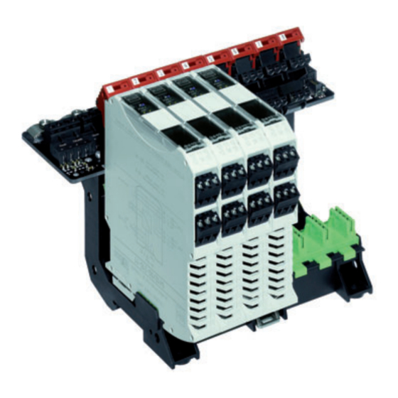
Main components 7.4 Main components of the bus-Carrier 12575E00 No. Components Function bus-Carrier Support for 8 Fieldbus Power Supplies, possibilities to connect the external power supply, the trunks, the hosts and the diagnosis messages pac bus Transmission of the external power supply to the individual Fieldbus Power Supplies Fieldbus Power Supply Supply of host and trunk with energy... -
Page 59: Dip Switch On The Bus-Carrier
Main components 7.5 DIP switch on the bus-Carrier WARNING Explosion hazard! Risk of death or severe injuries! It is not allowed to change the DIP switches in zone 2 while power is active! For an overview of the DIP switched on the bus-Carrier, see chapter "Main components of the bus-Carrier". -
Page 60: Assembly
Assembly Assembly 8.1 Assembly of the Fieldbus Power Supply on the DIN rail with and without pac-Bus. Assembly of the pac-Bus The components for the pac-Bus must be ordered separately (see chapter "Spare parts and accessories"). A maximum of 8 pac-Bus elements can be connected for a 24 V power supply. - Page 61 Assembly Assembly of the Fieldbus Power Supplies When pivoting the device onto the DIN rail, pay attention that it should not be set at an angle. 06885E00 Make sure that the position of the device on the DIN rail is correct (1). Pivot the device onto the DIN rail (2).
-
Page 62: Assembly Of The Fieldbus Power Supply On A Bus-Carrier
Assembly 8.2 Assembly of the Fieldbus Power Supply on a bus-Carrier The bus-Carrier can be installed on a mounting plate or on a DIN rail according to EN 50022 type NS35/7.5 or NS35/15. Assembly of the bus-Carrier on a mounting plate 08037E00 Place the device on the mounting plate (installation dimensions are indicated on the dimensional drawing). - Page 63 Assembly Assembly of the Fieldbus Power Supply on the bus-Carrier Before assembly of the Fieldbus Power Supply, all terminals on the base bolt side must be removed. 06883E00 Position the screwdriver behind the black and green terminal (1). Push out all terminals (2). 06887E00 Make sure that position of the device on the pac-Carrier is correct and swivel completely in.
-
Page 64: Installation
Installation Disassembly of the Fieldbus Power Supply from the bus-Carrier 06884E00 Insert the screwdriver in the red detent lever (1) and open the detent lever by swivelling the screwdriver. The device is pushed out of the slot (2). Remove the device. Installation WARNING Incorrectly installed components! -
Page 65: Assembly Of The Fieldbus Power Supply In The Simplex Mode On The Din Rail With And Without Pac-Bus
Installation 9.2 Assembly of the Fieldbus Power Supply in the Simplex mode on the DIN rail with and without pac-Bus. pac-bus 24 V Diag 24 V DC Diag Red. 2 Host Red. 1 bus-carrier Trunk 12573E00 Type 9412/00-310-11 Connecting the power supply without pac-Bus Connect the power supply to the green terminals 7 (+) and 9 (-) of the Fieldbus Power Supply. -
Page 66: Installation Of A Fieldbus Power Supply In Redundant Operation Or Boost Operation On A Din Rail With Or Without Pac-Bus
Installation 9.3 Installation of a Fieldbus Power Supply in redundant operation or Boost operation on a DIN rail with or without pac-Bus The wiring of the trunk and host connections in the redundant operation can be carried out via external terminals or by placing two conductors on a terminal near the Fieldbus Power Supply. - Page 67 Installation Power Supply connection without pac-Bus Connect the power supply to the green terminals 7 (+) and 9 (-) of the Fieldbus Power Supplies 1 and 2. Power supply connection with pac-Bus Connect the power supply to the terminals 1 (+) and 2 (-) of the pac-Bus. Connecting the error contact without pac-Bus Connect the error contact to the green terminals 8 (+) and 9 (-) of the Fieldbus Power Supplies 1 and 2.
-
Page 68: Installation Of The Fieldbus Power Supply In The Simplex Operation On The Bus-Carrier
Installation 9.4 Installation of the Fieldbus Power Supply in the Simplex operation on the bus-Carrier In the Simplex operation, each Fieldbus Power Supply supplies one segment with energy. Up to eight segments can be connected to each bus-Carrier. 12576E00 Type 9419/08F-XX0-..Connecting the power supply (not redundant) Connect the power supply to the terminals 2 (+) and 3 (-). - Page 69 Installation Removing the insulation of the connecting cable The fieldbus connecting cable is relieved and shielded by clamping it under the shield bus bar (max. tightening torque: 0.7 Nm). 12578E00 Remove the insulation of the connecting cable (1) according to the drawing. Turn down the bare shield (2) according to the drawing.
-
Page 70: Installation Of The Fieldbus Power Supply In The Redundant Operation Or Boost Operation On The Bus-Carrier
Installation 9.5 Installation of the Fieldbus Power Supply in the redundant operation or Boost operation on the bus-Carrier The redundant and Boost operation of the Fieldbus Power Supplies on the bus-Carriers is only possible if bus-Carriers of type 9419/08R are used. In the redundant operation, two neighbouring Fieldbus Power Supplies ensure the redundant supply of a segment. - Page 71 Installation Removing the insulation of the connecting cable The fieldbus connecting cable is relieved and shielded by clamping it under the shield bus bar (max. tightening torque: 0.7 Nm). 12578E00 Remove the insulation of the connecting cable (1) according to the drawing. Turn down the bare shield (2) according to the drawing.
-
Page 72: Commissioning
Danger due to improper maintenance/repair Explosion protection is not guaranteed any longer. Repair work to the device must only be performed by R. STAHL . Repair work is only to be performed by the manufacturer. No changes to the apparatus are permitted. -
Page 73: Accessories And Spare Parts
Accessories and Spare Parts 14 Accessories and Spare Parts Designation Illustration Description Order number Weight Labelling sheet 180 labels 160640 0.001 DIN A4 09900E00 Screw terminals green 112817 0.001 07099E00 black 112816 0.001 07093E00 Screw terminals with black 113005 0.001 test plug socket 07108E00 Spring-cage terminal... - Page 74 Accessories and Spare Parts Designation Illustration Description Order number Weight Feldbus Wizard Engineering tool for segment design of Fieldbus – – Engineering Engineering Tool Foundation or Profibus PA Fieldbus segments Tool Download under www.fieldbus-solutions.info 07376E00 Terminating resistor Fieldbus Terminator "Ex m" 9418/01-201-10 0.080 06501E00...
-
Page 75: Ec Type Examination Certificate
EC Type Examination Certificate (Page 1) 15 EC Type Examination Certificate (Page 1) 200744 / 941260310030 Fieldbus Power Supply System S-BA-9412-01-en-02/09/2009 9412/00-310, 9419/08... - Page 76 EC Type Examination Certificate (Page 1) Fieldbus Power Supply System 200744 / 941260310030 9412/00-310, 9419/08... S-BA-9412-01-en-02/09/2009...
-
Page 77: Ec Declaration Of Conformity
EC Declaration of Conformity 16 EC Declaration of Conformity 200744 / 941260310030 Fieldbus Power Supply System S-BA-9412-01-en-02/09/2009 9412/00-310, 9419/08... - Page 78 EC Declaration of Conformity Fieldbus Power Supply System 200744 / 941260310030 9412/00-310, 9419/08... S-BA-9412-01-en-02/09/2009...
- Page 80 200744 / 941260310030 S-BA-9412-01-de/en-02/09/2009...
Need help?
Do you have a question about the isbus 9419/08 Series and is the answer not in the manual?
Questions and answers