Chapters
Table of Contents

Related Manuals for Stahl 9470/33 Series


Summary of Contents for Stahl 9470/33 Series
- Page 1 Betriebsanleitung Additional languages r-stahl.com Digital Input Output Modul für Zone 2 Reihe 9470/33...
-
Page 2: Table Of Contents
Inhaltsverzeichnis Allgemeine Angaben ...................3 Hersteller ......................3 Angaben zur Betriebsanleitung ................3 Weitere Dokumente ....................3 Konformität zu Normen und Bestimmungen ............3 Erläuterung der Symbole ..................3 Symbole in der Betriebsanleitung ...............3 Warnhinweise .....................4 Symbole am Gerät ....................4 Sicherheitshinweise ....................5 Aufbewahrung der Betriebsanleitung ..............5 Qualifikation des Personals ................5 Sichere Verwendung ...................5 Umbauten und Änderungen ................6... -
Page 3: De De
Die Originalbetriebsanleitung ist die englische Ausgabe. Diese ist rechtsverbindlich in allen juristischen Angelegenheiten. Weitere Dokumente • Kopplungsbeschreibung IS1+ (Download unter r-stahl.com) • Anleitung "Erdung und Schirmung" (Download unter r-stahl.com) • Datenblatt Dokumente in weiteren Sprachen, siehe r-stahl.com. Konformität zu Normen und Bestimmungen Zertifikate und EU-Konformitätserklärung, siehe r-stahl.com. -
Page 4: 2.2 Warnhinweise
Erläuterung der Symbole Warnhinweise Warnhinweise unbedingt befolgen, um das konstruktive und durch den Betrieb bedingte Risiko zu minimieren. Die Warnhinweise sind wie folgt aufgebaut: • Signalwort: GEFAHR, WARNUNG, VORSICHT, HINWEIS • Art und Quelle der Gefahr/des Schadens • Folgen der Gefahr •... -
Page 5: Sicherheitshinweise
Normen und Bestimmungen umfasst. Für Tätigkeiten in explosionsgefährdeten Bereichen sind weitere Kenntnisse erforderlich! R. STAHL empfiehlt einen Kenntnisstand, der in folgenden Normen beschrieben wird: • IEC/EN 60079-14 (Projektierung, Auswahl und Errichtung elektrischer Anlagen) • IEC/EN 60079-17 (Prüfung und Instandhaltung elektrischer Anlagen) •... -
Page 6: Umbauten Und Änderungen
Sicherheitshinweise • Stromkreise der Zündschutzart "Ex i", die mit nicht-eigensicheren Stromkreisen betrieben wurden, dürfen danach nicht mehr als Stromkreise der Zündschutzart "Ex i" betrieben werden. • Gerät bei Einsatz in Zone 2 in ein schützendes Gehäuse oder einen Schrank gemäß IEC/EN 60079-0 einbauen, die jeweils eine geeignete Schutzart (mindestens IP54) aufweisen. -
Page 7: Funktion Und Geräteaufbau
Funktion und Geräteaufbau Funktion und Geräteaufbau GEFAHR Explosionsgefahr durch zweckentfremdete Verwendung! Nichtbeachten führt zu schweren oder tödlichen Verletzungen. • Gerät nur entsprechend den in dieser Betriebsanleitung festgelegten Betriebsbedingungen verwenden. • Gerät nur entsprechend dem in dieser Betriebsanleitung genannten Einsatzzweck verwenden. Funktion Einsatzbereich Das Digital Input Output Modul Typ 9470/33 ist für den Einsatz in... -
Page 8: 4.2 Geräteaufbau
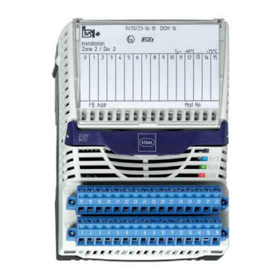
Funktion und Geräteaufbau Geräteaufbau Gerätelement Beschreibung Abdeckklappe Abdeckklappe mit Einlegeschild und Anschlussplan (geöffnet) Beschriftung Angaben zum Modul (Seriennummer, Hardware-Revisionsnummer, Software-Revisionsnummer, Herstelldatum, z.B.: 123456DE9999 Rev. A 01-01 0508) Rasthebel Rasthebel zum Entfernen des Moduls von der BusRail 15325E00 LED zur Anzeige Wartung ("M/S", blau), Betrieb ("RUN", grün) und Fehler ("ERR", rot) -
Page 9: Technische Daten
Technische Daten Technische Daten Explosionsschutz Global (IECEx) Gas und Staub IECEx DEK 12.0044X Ex ec ia [ia Ga] IIC T4 Gc [Ex ia Da] IIIC Europa (ATEX) Gas und Staub DEKRA 12ATEX0099 X E II 3 (1) G Ex ec ia [ia Ga] IIC T4 Gc E II (1) D [Ex ia Da] IIIC Bescheinigungen und Zertifikate Bescheinigungen... - Page 10 Technische Daten Explosionsschutz 2 Kanäle parallel Max. Strom I 20,8 mA Max. Leistung P 51 mW Max. innere 5 nF Kapazität C Max. anschließbare Induktivität L Kapazität C [mH] 100 50 0,02 [μF] 0,44 0,57 0,67 0,77 0,93 1,1 IIB/IIIC [mH] 270 100 50 0,01 [μF]...
- Page 11 Technische Daten Technische Daten Frequenzeingang Max. Anzahl Kanäle Max. 20 kHz (bei Frequenzen > 1 kHz verringert sich die maximale Leitungslänge, Schaltfrequenz z.B. bei 5 kHz auf ca. 75 m) Min. Pulsbreite 25 μs Messbereich 0,1 … 600 Hz 1 Hz … 3 kHz* 1 Hz …...
- Page 12 Technische Daten Technische Daten Signalübertragung Max. < 1 ms Verzögerung von Signal / interner Bus Max. Filter ohne klein mittel groß Verzögerung Frequenz- Frequenz eingang / 0,1 Hz ( f < 1 Hz 1/f + 1 ms interner Bus 1 Hz ( f < 10 Hz 1/f + 1 ms 18/f 10 Hz ( f <...
- Page 13 Technische Daten Technische Daten Hilfsenergie Ausführung Eigensicher Ex ia über BusRail Max. 120 mA Stromaufnahme Max. Leistungs- 2,5 W aufnahme Max. 2,5 W Verlustleistung Gerätespezifische Daten Einstellungen Modul Diagnose- EIN / AUS Meldung Signal Signal-Typ Eingang / Ausgang *) Impuls- 0 s / Aus;...
- Page 14 Bei Ausgängen ist Drahtbruch-/Kurzschlusserkennung nur im EIN-Zustand möglich. Montage / Installation Einbaubedingungen Einbaulage waagrecht oder senkrecht (Betriebsanleitung beachten) Montageart auf 35-mm-DIN-Schiene NS 35/15 (DIN EN 60715) Weitere technische Daten, siehe r-stahl.com. Digital Input Output Modul für Zone 2 218130 / 9470613310 Reihe 9470/33 2020-07-17·BA00·III·de·02...
-
Page 15: Projektierung
Projektierung Projektierung HINWEIS Ausfall der installierten Geräte im Schaltschrank durch zu hohe Umgebungstemperatur! Nichtbeachten kann zu Sachschäden führen. • Schaltschrank so aufbauen und einrichten, dass er immer innerhalb des zulässigen Temperaturbereichs betrieben wird. Bei der Projektierung folgende Bedingungen beachten: • Installation des Geräts zur bestimmungsgemäßen Verwendung nur auf der IS1 BusRail 9494. -
Page 16: 6.2 Betriebsmodus "Frequenz" Oder "Zähler
Projektierung Zur Erhöhung der Ausgangsleistung dürfen Kanäle parallel geschaltet werden. Daraus ergeben sich neue sicherheitstechnische Daten (siehe Kapitel "Technische Daten"). Optional können nicht verwendete Kanäle mit Widerständen (einfaches elektrisches Betriebsmittel für eigensichere Stromkreise gemäß EN 60079-11) bestückt werden, um die Störmeldungen der jeweiligen Kanäle zu unterdrücken. -
Page 17: Is1+ Kompatible Low-Power-Aktuatoren
Stellungsregler Typ 3766 Festo (Seitz) Magnetventil PV12 F73 Xio H 6,4 V R. Stahl Schaltgeräte LED Leuchtmelder 8010/C1661 Transport und Lagerung • Gerät nur in Originalverpackung transportieren und lagern. • Gerät trocken (keine Betauung) und erschütterungsfrei lagern. • Gerät nicht stürzen. -
Page 18: Montage Und Installation
Montage und Installation Montage und Installation Das Gerät ist für den Einsatz in gasexplosionsgefährdeten Bereichen der Zone 2, in staubexplosionsgefährdeten Bereichen der Zonen 21 und 22 sowie auch im sicheren Bereich zugelassen. Wenn in der Anlage starke elektromagnetische Störquellen vorhanden sind oder die Leitungen länger als 30 m sind, wird empfohlen, geschirmte Feldkabel zu verwenden, um die spezifizierte Genauigkeit zu erreichen. - Page 19 Montage und Installation 2073E00 Montage auf BusRail • Modul senkrecht auf vorgesehenen Steckplatz der BusRail aufsetzen und durch leichtes Drücken einrasten. • Um sicherzustellen, dass das Modul richtig eingerastet ist, nochmals links und rechts das Modul auf die BusRail drücken! Zwischen Modul und BusRail sollte keine Lücke sein! Modul darf sich ohne Betätigen des...
- Page 20 Montage und Installation Demontage • Schrauben der steckbaren Klemmen X1 und X2 lösen. • Steckbare Klemme X1 und X2 vom auszutauschenden Modul abziehen. • Gegebenenfalls Trennwand entfernen. • Blauen Rasthebel des Moduls nach oben ziehen, um das Modul zu entriegeln. •...
-
Page 21: Installation
Montage und Installation Austausch von Modulen Beim Austausch des Moduls durch ein baugleiches Modul werden die eingestellten Parameter übernommen. Es sind keine weiteren Einstellungen notwendig. Beim Austausch des Moduls durch ein Modul mit anderer Funktion meldet das Modul einen Konfigurationsfehler (rote LED "ERR" blinkt). -
Page 22: Inbetriebnahme
Inbetriebnahme Inbetriebnahme Vor Inbetriebnahme Folgendes sicherstellen: • Vorschriftsmäßige Installation des Gerätes. • Richtiger Anschluss der Kabel. • Keine Schäden am Gerät und an Anschlusskabeln. • Fester Sitz der Schrauben an den Klemmen. Richtiges Anzugsdrehmoment: 0,5 ... 0,6 Nm. Betrieb 10.1 Anzeigen Entsprechende LEDs am Gerät zeigen den Betriebszustand des Geräts an (siehe auch Kapitel "Funktion und Geräteaufbau"). - Page 23 Unzulässige Änderung der • Modul ersetzen Steckplatzadresse Wenn sich der Fehler mit den genannten Vorgehensweisen nicht beheben lässt: • An R. STAHL Schaltgeräte GmbH wenden. Zur schnellen Bearbeitung folgende Angaben bereithalten: • Typ und Seriennummer des Geräts • DCS/SPS • Protokoll •...
-
Page 24: Instandhaltung, Wartung, Reparatur
11.3 Reparatur GEFAHR Explosionsgefahr durch unsachgemäße Reparatur! Nichtbeachten führt zu schweren oder tödlichen Verletzungen. • Reparaturen an den Geräten ausschließlich durch R. STAHL Schaltgeräte GmbH ausführen lassen. Digital Input Output Modul für Zone 2 218130 / 9470613310 Reihe 9470/33 2020-07-17·BA00·III·de·02... -
Page 25: Rücksendung
Reinigung 11.4 Rücksendung • Rücksendung bzw. Verpackung der Geräte nur in Absprache mit R. STAHL durchführen! Dazu mit der zuständigen Vertretung von R. STAHL Kontakt aufnehmen. Für die Rücksendung im Reparatur- bzw. Servicefall steht der Kundenservice von R. STAHL zur Verfügung. - Page 27 Operating instructions Additional languages r-stahl.com Digital Input Output Module for Zone 2 Series 9470/33...
- Page 28 Contents General Information ....................3 Manufacturer .......................3 Information regarding the Operating Instructions ..........3 Further Documents .....................3 Conformity with Standards and Regulations ............3 Explanation of the Symbols ................3 Symbols in these Operating Instructions ............3 Warning Notes ....................4 Symbols on the Device ..................4 Safety Notes .......................5 Operating Instructions Storage ................5 Personnel Qualification ..................5...
-
Page 29: En En
They are legally binding in all legal affairs. Further Documents • IS1+ coupling description (download from r-stahl.com) • "Earthing and shielding" instructions (download from r-stahl.com) • Data sheet For documents in additional languages, see r-stahl.com. Conformity with Standards and Regulations See certificates and EU Declaration of Conformity: r-stahl.com. -
Page 30: 2.2 Warning Notes
Explanation of the Symbols Warning Notes Warnings must be observed under all circumstances, in order to minimize the risk due to construction and operation. The warning notes have the following structure: • Signalling word: DANGER, WARNING, CAUTION, NOTICE • Type and source of danger/damage •... -
Page 31: Safety Notes
• Use the device in accordance with its intended and approved purpose only. • Always consult with R. STAHL Schaltgeräte GmbH if using the device under operating conditions which are not covered by the technical data. • Make sure that the device is not damaged. -
Page 32: Modifications And Alterations
Safety Notes • Electrical circuits with the "Ex i" type of protection may no longer be operated as electrical circuits with this type of protection after being operated with non-intrinsically safe electrical circuits. • When used in Zone 2, the device is to be installed in a protective enclosure or in a cabinet according to IEC/EN 60079-0. -
Page 33: Function And Device Design
Function and Device Design Function and Device Design DANGER Explosion hazard due to improper use! Non-compliance results in severe or fatal injuries. • Use the device only in accordance with the operating conditions described in these operating instructions. • Use the device only for the intended purpose specified in these operating instructions. -
Page 34: 4.2 Device Design
Function and Device Design Device Design Device component Description Cover flap Cover flap with insert disc and connection diagram (open) Labelling Module data (Serial number, hardware revision number, software revision number, date of manufacture, e.g.: 123456DE9999 Rev. A 01-01 0508) Notch lever Notch lever for removing the module from the BusRail... -
Page 35: Technical Data
Technical Data Technical Data Explosion Protection Global (IECEx) Gas and dust IECEx DEK 12.0044X Ex ec ia [ia Ga] IIC T4 Gc [Ex ia Da] IIIC Europe (ATEX) Gas and dust DEKRA 12ATEX0099 X E II 3 (1) G Ex ec ia [ia Ga] IIC T4 Gc E II (1) D [Ex ia Da] IIIC Certifications and certificates Certificates... - Page 36 Technical Data Explosion Protection 2 channels in parallel Max. current I 20.8 mA Max. power P 51 mW Max. internal 5 nF capacity C Max. connectable inductance L capacity C [mH] 100 50 0.02 [μF] 0.44 0.57 0.67 0.77 0.93 1.1 IIB/IIIC [mH] 270 100 50 0.01...
- Page 37 Technical Data Technical Data Frequency input Max. number of channels Max. switching 20 kHz (at frequencies > 1 kHz the maximum conductor length is reduced, frequency e.g. at 5 kHz to approx. 75 m) Min. pulse width 25 μs Measuring range 0.1 to 600 Hz 1 Hz to 3 kHz* 1 Hz to 20 kHz Resolution...
- Page 38 Technical Data Technical Data Signal transmission Max. delay < 1 ms from signal / internal bus Max. delay Filter without small medium large from frequency input / Frequency internal bus 0.1 Hz ( f < 1 Hz 1/f + 1 ms 1 Hz ( f <...
- Page 39 Technical Data Technical Data Auxiliary power Version Intrinsically safe Ex ia via BusRail Max. current 120 mA consumption Max. power 2.5 W consumption Max. power 2.5 W dissipation Device-specific data Settings Module Diagnostics ON / OFF message Signal Signal type Input / output*) Pulse 0 s / off;...
- Page 40 Mounting horizontal or vertical (observe operating instructions) orientation Mounting type on 35 mm DIN rail NS 35/15 (DIN EN 60715) For further technical data, see r-stahl.com. Digital Input Output Module for Zone 2 218130 / 9470613310 Series 9470/33 2020-07-17·BA00·III·en·02...
-
Page 41: Engineering
Engineering Engineering NOTICE An ambient temperature that is too high may cause failure of the devices installed in the cabinet. Non-compliance can result in material damage. • Install and adjust the cabinet in such a way that it is always operated within the permissible temperature range. -
Page 42: Frequency" Or "Counter" Operating Mode
Engineering Channels may be connected in parallel to increase the power output. This results in new safety data (see "Technical data" chapter). Optionally, non-used channels with resistors (simple apparatus for intrinsically safe circuits according to EN 60079-11) can be equipped in rder to suppress the error messages of the respective channels. -
Page 43: Is1+ Compatible Low Power Actuators
Type 3766 Festo (Seitz) Solenoid valve PV12 F73 Xio H 6.4 V R. Stahl Schaltgeräte LED indicator lamp 8010/C1661 Transport and Storage • Transport and store the device only in the original packaging. • Store the device in a dry place (no condensation) and vibration-free. -
Page 44: Mounting And Installation
Mounting and Installation Mounting and Installation The device is approved for use in gas hazardous areas of Zone 2, dust hazardous areas of Zones 21 and 22, and safe areas. If the installation has strong electromagnetic sources of interference or the electrical lines are more than 30 m long, use of shielded field cables is recommended to achieve the specified data. - Page 45 Mounting and Installation 2073E00 Mounting on BusRail • Position the module vertically at the intended slot of the BusRail and press lightly to snap it into place. • Press the module down onto the BusRail on the left and right to ensure that it is properly secured! There should not be any gap between the module and BusRail! The module...
- Page 46 Mounting and Installation Removal • Loosen the screws of pluggable terminals X1 and X2. • Disconnect pluggable terminals X1 and X2 from the module to be replaced. • If necessary, remove the partition. • Pull the blue notch lever of the module upwards to unlock the module.
-
Page 47: Installation
Mounting and Installation Replacing modules When replacing the module with a module with identical design, the set parameters are maintained. No further user adjustments are necessary. When replacing the module with a module with a different function, the module reports a configuration error (red "ERR" LED flashes). The module must be either re-configured or replaced with a module of correct type. -
Page 48: Commissioning
Commissioning Commissioning Before commissioning, ensure the following: • Installation of the device according to regulations. • Correct connection of the cables. • No damage at the device and connection cables. • Tight seat of the screws at the terminals. Correct tightening torque: 0.5 to 0.6 Nm. Operation 10.1 Indications The corresponding LEDs on the device indicate the operating state of the device... - Page 49 • Replace the module If the error cannot be eliminated using the specified procedures: • Contact R. STAHL Schaltgeräte GmbH. For rapid processing, have the following information ready: • Type and serial number of the device • DCS/PLC •...
-
Page 50: Maintenance, Overhaul, Repair
Explosion hazard due to improper repair! Non-compliance results in severe or fatal injuries. • Repair work on the devices must be performed only by R. STAHL Schaltgeräte GmbH. Digital Input Output Module for Zone 2 218130 / 9470613310 Series 9470/33... -
Page 51: Returning The Device
• Only return or package the devices after consulting R. STAHL! Contact the responsible representative from R. STAHL. R. STAHL's customer service is available to handle returns if repair or service is required. • Contact customer service personally. • Go to the r-stahl.com website. - Page 53 Nonhazardous The Type 9470 Digital Input Output Module is designed to receive up Class I, II, III, Division 2, Group A-G to 16 discrete input signals from dry contacts and NAMUR proximity or Class I, Zone 2, Group IIC/IIB sensors etc. and transfer them to the IS1 CPU & Power Module. It is Hazardous (Classified) Locations also possible to drive low power valves.
Need help?
Do you have a question about the 9470/33 Series and is the answer not in the manual?
Questions and answers