Advertisement

Quick Links

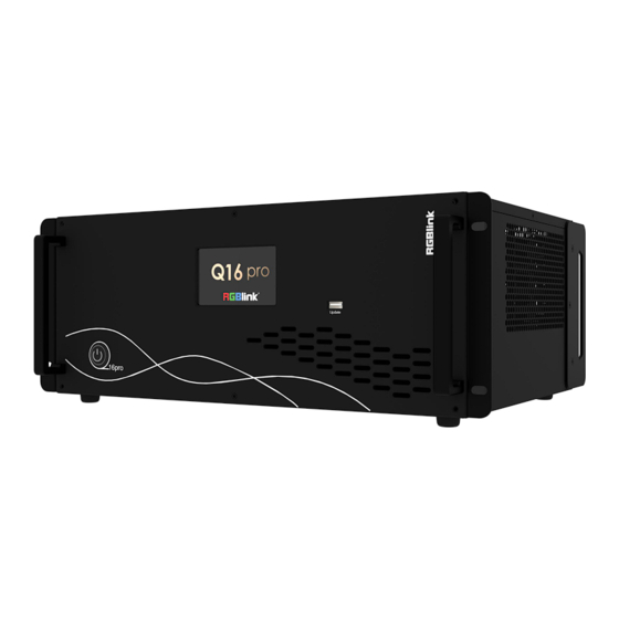
Q16pro
Quick Start
● Each module support 8 screens spanning the output port without
occupying layers
● 12 bit input and output, RGB 4:4:4 color space
● Dual independent OSD rolling subtitles
● Multi-window monitoring for inputs and outputs
● i signal output supported
● LOGO overlay
● Seamless switch between signals and scenes
● Dual power module backup

Advertisement

Table of Contents
loading
Need help?

Need help?

Do you have a question about the Q Series and is the answer not in the manual?

Questions and answers

Subscribe to Our Youtube Channel

Summary of Contents for RGBlink Q Series

  • Page 1 Q16pro Quick Start ● Each module support 8 screens spanning the output port without occupying layers ● 12 bit input and output, RGB 4:4:4 color space ● Dual independent OSD rolling subtitles ● Multi-window monitoring for inputs and outputs ● i signal output supported ●...
  • Page 2: Table Of Contents

    Content Product Overview ................................1 Hardware Orientation ..............................2 Q16pro Front Panel ..............................2 Q16pro Rear Panel ..............................3 Install Your Product .................................4 Connect Input Signal Source ..........................4 Connect Output Source ............................5 Connect Control Computer ............................ 5 Turn on Your Q16pro .............................. 6 Use Your Product ................................
  • Page 3: Product Overview

    DP 1.2, HDMI 2 .0 and other ultra-high resolution 4K/8K signal input and output, easily realize 4K multi-screen point-to-point splicing. System Connection RGBlink offers solutions to demanding technical problem. Any application questions, or required further information, please contact with our customer Support Engineers. Q16pro System Connection Diagram ©...
  • Page 4: Hardware Orientation

    Upgrade, Language and Version (Please refer to user manual for specific menu operation steps.) USB Port For device upgrade Power Switch To turn on/off device © Xiamen RGBlink Science & Technology Co., Ltd. Ph: +86 592 5771197 | support@rgblink.com | www.rgblink.com...
  • Page 5: Q16Pro Rear Panel

    IN is used to accept the sync signal; LOOP is used to loop the sync signal. 2U (to be published) supports single power supply, 4U and Power Module above supports double power supply module. © Xiamen RGBlink Science & Technology Co., Ltd. Ph: +86 592 5771197 | support@rgblink.com | www.rgblink.com...
  • Page 6: Install Your Product

    Q16pro series supports HDMI, DVI, SDI, DP1.2, HDBaseT and other optional input modules. Connect Q16pro with IP Camera, PC, DVD, laptop and other device as shown in the figure above. © Xiamen RGBlink Science & Technology Co., Ltd. Ph: +86 592 5771197 | support@rgblink.com | www.rgblink.com...
  • Page 7: Connect Output Source

    Control Computer Router/Switch Connection: Connect control computer and Q16pro with Router or Switch. It supports simultaneous online operation by multiple users. Router Control Computer © Xiamen RGBlink Science & Technology Co., Ltd. Ph: +86 592 5771197 | support@rgblink.com | www.rgblink.com...
  • Page 8: Turn On Your Q16Pro

    Turn on Your Q16pro After connection, slightly press the power button in the front panel to turn on Q16pro. © Xiamen RGBlink Science & Technology Co., Ltd. Ph: +86 592 5771197 | support@rgblink.com | www.rgblink.com...
  • Page 9: Use Your Product

    ENTER Light on if Switch Mode is triggered. Push ENTER button again to return to Matrix Mode. (more details please refer to 3.1.4.3 Switch Mode) 2.Used as confirm button under menu operation. © Xiamen RGBlink Science & Technology Co., Ltd. Ph: +86 592 5771197 | support@rgblink.com | www.rgblink.com...
  • Page 10 3. Press OUT 1-16 to load OSD 2 to selected output port under OSD Mode. 4. Used as Numeric Keys under menu control; 1-9 indicate number 1-9, 10 indicates number 0. © Xiamen RGBlink Science & Technology Co., Ltd. Ph: +86 592 5771197 | support@rgblink.com | www.rgblink.com...
  • Page 11: Cpx Rear Panel

    CPX.) User should firstly choose Q16pro as the controlled device. Please refer to following steps for device selection: 【Menu】-->>【Search】-->>【Select Device】-->>【Q16pro】 © Xiamen RGBlink Science & Technology Co., Ltd. Ph: +86 592 5771197 | support@rgblink.com | www.rgblink.com...
  • Page 12: Xpose Controls Q16Pro

    4. Click the device you need in the <All Devices> list. 5. Click in the <Chosen Device>. © Xiamen RGBlink Science & Technology Co., Ltd. Ph: +86 592 5771197 | support@rgblink.com | www.rgblink.com...
  • Page 13: Input Setting

    Communication Board with PVW When there is communication Board with PVW input module installed on Q16pro, you can click HDMI port for following operations. © Xiamen RGBlink Science & Technology Co., Ltd. Ph: +86 592 5771197 | support@rgblink.com | www.rgblink.com...
  • Page 14 Window Index: Select window to display OSD PVW: Display Mode:Preview Input ONLY Equal:Select layout you need Input Monitor: Select input signal for each window © Xiamen RGBlink Science & Technology Co., Ltd. Ph: +86 592 5771197 | support@rgblink.com | www.rgblink.com...
  • Page 15: Output Setting

    ●Quad DVI Output Module (to be published) ●Dual HDMI 2.0 Output Module (to be published) ●IP Output Module (to be published) Order Codes please refer to 4.2 Chapter. © Xiamen RGBlink Science & Technology Co., Ltd. Ph: +86 592 5771197 | support@rgblink.com | www.rgblink.com...
  • Page 16 Output Port: current port Logo ID: Load Logo ID been saved Status: Hide/Show Logo X/Y: Horizontal and vertical position of Logo Delete Logo: Clear logo set already © Xiamen RGBlink Science & Technology Co., Ltd. Ph: +86 592 5771197 | support@rgblink.com | www.rgblink.com...
  • Page 17 “..” indicates that there are no output modules,as shown in the right figure. IP:Support auto/manual setting. Show IP Address, Netmask, Gateway Fan Control: Support auto/manual setting. Fan Speed: 0-100 © Xiamen RGBlink Science & Technology Co., Ltd. Ph: +86 592 5771197 | support@rgblink.com | www.rgblink.com...
  • Page 18: Display Management

    Display System is for users to set layout of outputs. Click this icon first and then click enter the interface. Container Container here means the Display Area. © Xiamen RGBlink Science & Technology Co., Ltd. Ph: +86 592 5771197 | support@rgblink.com | www.rgblink.com...
  • Page 19 2. Click <Create>,the container will display in the interface, and shows the width and height of each Display. 3. Click<Save> to save the container. © Xiamen RGBlink Science & Technology Co., Ltd. Ph: +86 592 5771197 | support@rgblink.com | www.rgblink.com...
  • Page 20: Layer Management

    Display Area When enter Layer Management interface, the window is blank. The screen group created in Display System shall be dragged from the Display Area. © Xiamen RGBlink Science & Technology Co., Ltd. Ph: +86 592 5771197 | support@rgblink.com | www.rgblink.com...
  • Page 21 1. Use the bar under the interface Choose one layer and the bar shows its signal source, type in position and size. click Set to confirm. © Xiamen RGBlink Science & Technology Co., Ltd. Ph: +86 592 5771197 | support@rgblink.com | www.rgblink.com...
  • Page 22 3. All Monitors: set close or on 4. Layer Set: set layer layout Drag and drop the source from the Signal List. After setting,click <Set> to confirm. © Xiamen RGBlink Science & Technology Co., Ltd. Ph: +86 592 5771197 | support@rgblink.com | www.rgblink.com...
  • Page 23 Display Area but it doesn’t work when cross over display area. © Xiamen RGBlink Science & Technology Co., Ltd. Ph: +86 592 5771197 | support@rgblink.com | www.rgblink.com...
  • Page 24: Preset Management

    Click<Script>, fill in the file name and click “Save”,the file can be seen in the <Load Script> Click Load to load the file into XPOSE. Click Delete to delete saved script. © Xiamen RGBlink Science & Technology Co., Ltd. Ph: +86 592 5771197 | support@rgblink.com | www.rgblink.com...
  • Page 25 3. Choose the BANK 4. Fill in the “Duration” 5. Click “OK” Users can click to edit and to delete. After settings done, turn on Loop Switch. © Xiamen RGBlink Science & Technology Co., Ltd. Ph: +86 592 5771197 | support@rgblink.com | www.rgblink.com...
  • Page 26: System Setting

    Drag Input, Output, Layer and Preset from the list to the keys you desired as shown in the figure: Please note the keyboard area where allows to set short cut keys © Xiamen RGBlink Science & Technology Co., Ltd. Ph: +86 592 5771197 | support@rgblink.com | www.rgblink.com...
  • Page 27 Edit: Edit user name and password. Delete: Delete user name and password. Permission: functions on this XPOSE 2.0 on this computer that the users are allowed to operate. © Xiamen RGBlink Science & Technology Co., Ltd. Ph: +86 592 5771197 | support@rgblink.com | www.rgblink.com...
  • Page 28 3. click ON,the tow device are connected when the red pot turns to be green one 4. click OFF to disconnect, it could not control two device at the same time. © Xiamen RGBlink Science & Technology Co., Ltd. Ph: +86 592 5771197 | support@rgblink.com | www.rgblink.com...
  • Page 29 All video products are designed and tested to the highest quality standard and backed by full 1 years parts and labor warranty. Warranties are effective upon delivery date to customer and are non-transferable. RGBlink warranties are only valid to the original purchase/owner. Warranty related repairs include parts and labor, but do not include faults resulting from user negligence, special modification, lighting strikes, abuse(drop/crush), and/or other unusual damages.

This manual is also suitable for:

Q16pro seriesQ16pro 4u

Table of Contents