
Related Manuals for RGBlink Q16pro-2


Summary of Contents for RGBlink Q16pro-2
- Page 1 Q16pro 2022 User Manual Article NO: RGB-RD-UM-Q16pro 2022 E000 Version NO: V1.0 Q16pro User Manual...
-
Page 2: Table Of Contents
Content Content....................................2 Declarations..................................3 FCC/Warranty................................3 Operators Safety Summary............................. 4 Installation Safety Summary........................... 4 Chapter 1 Your Product...............................6 1.1 Product Overview............................6 1.2 Key Features..............................6 1.3 Front Panel..............................7 1.3.1 Main Menu.............................7 1.4 Rear Panel..............................13 1.5 Demension..............................15 Chapter 2 Install Your Product..........................17 2.1 Plug in Power............................... -
Page 3: Declarations
RGBlink. If the purchaser or a third party carries out modifications or repairs on goods delivered by RGBlink, or if the goods are handled incorrectly, in particular if the systems are commissioned operated incorrectly or if, after the transfer of risks, the goods are subject to influences not agreed upon in the contract, all guarantee claims of the purchaser will be rendered invalid. -
Page 4: Operators Safety Summary
Operators Safety Summary The general safety information in this summary is for operating personnel. Do Not Remove Covers or Panels There are no user-serviceable parts within the unit. Removal of the top cover will expose dangerous voltages. To avoid personal injury, do not remove the top cover. Do not operate the unit without the cover installed. Power Source This product is intended to operate from a power source that will not apply more than 230 volts rms between the supply conductors or between both supply conductor and ground. - Page 5 Unpacking and Inspection Before opening product shipping box, inspect it for damage. If you find any damage, notify the shipping carrier immediately for all claims adjustments. As you open the box, compare its contents against the packing slip. If you find any shortages, contact your sales representative.
-
Page 6: Chapter 1 Your Product
Chapter 1 Your Product 1.1 Product Overview Q16pro is a high-performance video image processing system and high-performance video splicing server using pure hardware and leading-edge FPGA processing architecture. Offering a range of input and output signals via a card-based structure, and supporting hot swap of modules, and options including redundant power supplies, Q16pro is a stable high-performance platform that can be deployed in varied applications including corporate and visual messaging as well in retail and digital signage applications。... -
Page 7: Front Panel
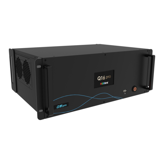
1.3 Front Panel Q16pro-4 LCD Touch Screen USB Port: for device upgrade Power Switch: to turn on/off device 1.3.1 Main Menu After powered on, the LCD touch screen will show LOGO and then enter the main menu. Main Menu include: Device, Settings,Load, Upgrade, English and Version. - Page 8 1.3.1.1 Decive Click [Device], the LCD screen will show the rear panel of Q16pro. Green indicates there is a signal for interface. Grey indicates no signal for interface. 1.3.1.2 Settings Click [Settings] to enter the page, which includes Communication Settings, Fan Control, Factory Reset. Q16pro User Manual...
- Page 9 Communication Settings Click [Communication Settings] to do settings of IP and Serial Communication. IP Settings: Display IP address of the device by default. You can turn off DHCP to manually set the IP address, subnet mask and gateway. Then click [Save] on the right corner to save parameters. Serial Communication: COM Port: default COM port.
- Page 10 If the temperature of the device exceeds 70℃, a high temperature prompt will pop up on the LCD screen as shown above. Factory Reset Click [Factory Reset] to enter the interface. In this interface, you can choose to Reset IP or Reset EDID. You can also choose to Reset both EDID and IP if necessary.
- Page 11 1.3.1.3 Load Click [Load] to enter the interface of load bank. Page: 16 pages optional Bank: 16 banks in each page. Yellow backgrond: current bank; Green background: with parameter saved; Grey background: empty bank When the user selects the desired bank, the interface will pop up "Do you want to Load Bank X", shown as below. Click [Confirm] to do the selection.
- Page 12 If the user has inserted the USB disk, the interface will pop up a prompt for device upgrade. If the user selects "Confirm", the interface will start upgrading and show the progress bar. After upgrade is completed, the interface will pop up a prompt to restart the device. Click [Confirm] to restart. 1.3.1.5 Chinese/English Click [Chinese/English] for language switching.
-
Page 13: Rear Panel
Click [Version] for overview of version info. The version of communication board, input boards and output boards will be shown in this interface. 1.4 Rear Panel Q16pro-2 Input slots 1-3, supporting HDMI, DP and other optional Purple Input 1-3 modules. - Page 14 Power Interface, support single power supply. Q16pro-4 Input slots 1-4, supporting HDMI,DVI,SDI,DP and other Purple Input 1-4 optional modules. Output slots 1-5, supporting HDMI,DVI,SDI,DP and other Blue Output 1-5 optional output modules, supporting input modules Communication board with LAN and RS232 port, to connect Yellow COMM router or computer to realize software control.
-
Page 15: Demension
1.5 Demension Q16pro-2 Dimension of Q16pro-2: 483.4mm x 377mm x 89mm Q16pro User Manual... - Page 16 Q16pro-4 Dimension of Q16pro-4: 483.4mm x 446mm x 178mm Q16pro User Manual...
-
Page 17: Chapter 2 Install Your Product
Chapter 2 Install Your Product 2.1 Plug in Power This chapter takes Q16pro-4 as the example, other models, such as Q16pro-2 is also applicable to operations in this chapter. Connect power and Q16pro-4 with standard AC Power Cord. 2.2 Connect Signal Source and Control Computer Q16pro supports HDMI、SDI、DP1.2、HDMI 2.0 and other optional input and output modules. -
Page 18: Turn On Your Product
2.3 Turn on Your Product After connection, slightly press the power button in the front panel to turn on Q16pro. Q16pro User Manual... -
Page 19: Chapter 3 Use Your Product
Chapter 3 Use Your Product 3.1 XPOSE 2.0 Installation Note:The following XPOSE operation takes Q16pro-4 as an example, and other models operate the same except for the difference of interface. Environment Requirements: Window Processor: 1 GHz or above 32 bit or 64 bit processor Memory: 4 GB or more Graphics: Support Direct X9 128M or above (open AERO effect) Hard disk space: Above 16G (primary partitions, NTFS format) - Page 20 2. Click “Next” to install 3. Click “Browse...” to select the XPOSE software install location Click “Install” 4. During installation, it will pop up the window of Install Shield Wizard for Virtual Com port Q16pro User Manual...
- Page 21 5. click “Next” 6. Then click “Install", as shown in the figure 7. Click “Finish” and complete the installation, as shown in the figure below Q16pro User Manual...
-
Page 22: Xpose Operation
Please note that the email shall be invalid and complete otherwise Registration&Activation code cannot be received. Click Activate and scan the QR code an email from ill be sent to the RGBlink Registrations w Register email address. Type in the activate code and confirm. Q16pro User Manual... - Page 23 Type in the activate code and confirm. Keep the user name as “Admin” and password blank and then click Start Now. If exact Name and Password are needed, users can set up them in Authorization Setting under System Setting. After login, users can find the management including:Topology Diagram,Search,Display System,Layer Management, Preset Management, Keyboard Settings.
-
Page 24: System Setting
3.2.2 System Setting Click to enter <System Setting>interface. Find Device : New version of XPOSE 2.0 is blank default in Find Device. Users are supposed to choose the device needed in System Setting. Software Version:check current version Language:Chinese/English/Russia Keyboard Management: click <keyboard> it will redirected to keyboard setting window. - Page 25 Please note the keyboard area where allows to set short cut keys If the setting goes wrong or no need for short cut keys any more, click to clear some keys or clear all. Clear: is to clear some keys, the keys need to selected before hand.
- Page 26 Authorization Setting Click to open up the authorization entry. New:Add new USER NAME and PASSWORD Edit: Edit user name and password already built. Delete: Delete user name and password already built. Permission: functions on this XPOSE 2.0 on this computer that the users are allowed to operate. Click the green block to remove the function not to be permitted.
-
Page 27: Output|Input|Overview
Slave Unit: Click Slave Unit Slave Unit is to control multiple devices simultaneously, which are connected to same network. (“In the same network” means that the the third section in the IP address digits are the same ) XPOSE do operation on one device, same operation synchronized to other devices. - Page 28 Device Connection 1. Click the device you need in the <All Devices> list. 2. click in the <Chosen Device>. Output Setting Click any output port, the board where the port locates is selected. Users can do settings to the port now.
- Page 29 Input Setting Click any input port, the board where the port locates is selected. Users can do settings to the port now. A red rectangle flashes around the chosen port when it is clicked. Property Setting Input Port:chosen port Scale: X/Y:the starting horizontal and vertical position Width/Height : the horizontal and vertical size of scale...
- Page 30 Overview Click Return , there are overview, IP, Fan Control, Backup, Power On, Factory Setting. Device Info: users can check current temperature and MAC information Input Module Info : users can check current input module name and MCU version “..” indicates that there are no input modules,as shown in the right figure.
- Page 31 Fan Control: Support auto/manual setting. Fan Speed: 0-100 Notice: To avoid insufficient heat dissipation, the recommended manual fan speed is not less than Backup: You can choose to turn on/off backup. Backup Mode: Input Backup, Preset Backup Power on: Set power-on time. Factory Setting Remove EDID: Clear the previous EDID parameter.
-
Page 32: Display Management
3.2.4 Display Management Display System is for users to set layout of outputs. Click this icon first and then click enter the interface. Container: Container here means the Display Area, for example it could be a formed LED screen or an array of LCDs. Template There are 16 types of basic “Display Area”... - Page 33 Mode Each mode is marked in different color and provided with fitted templates. Users can do operations like splice under Presentation Mode. Q16pro:Presentation Mode and Matric Mode optional. Presentation Mode: No container is reserved after change of resolution. Need of recreating a container. Matrix Mode: No need of recreating a container after changing resolution.
- Page 34 Customize Container Click this icon at the bottom of template list. Monitor Layout: Auto or Manual Steps of create container are as follows: 1. Fill in H Total/V Total and Row/Column,it will calculate H item and V item automatically. For example, if you would like to create a container with 2 rows and 3 columns and each display has a width of 1920 and a height of 1080, the total width will be 5760 and the total height will be 2160.
-
Page 35: Layer Management
Display Output List: White one:available Gray one:unavailable Operation Steps: Left-mouse click the output and drag it to the display of the set container. Replacement: Drag and drop the output into the corresponding Display. The output being replaced will turns from gray to white in the list. - Page 36 Display Area When enter Layer Management interface, the window is blank. The screen group created in Display System shall be dragged from the Display Area. Signal Signal list, showing all input signals and resolutions currently. Drag the signal to the display. click ,users can rename the input signal and then click...
- Page 37 Layer Adjustment: there are two ways to adjust layer. 1. Use the bar under the interface Choose one layer and the bar shows its signal source, type in position and size. click Set to confirm. 2. Layer Scale and Crop Choose one layer needed to be adjusted,and type in its position and size.
- Page 38 Layer Set :to crop the layer :lock the layer to prevent misoperations :max to cover up the monitor. : cover up all monitors in the same screen group with the one signal. Layer Copy Press Ctrl and mouse left at the same time, move the mouse the layer selected can be copied and place in any monitor in the same Display Area but it doesn’t work when cross over display area.
-
Page 39: Preset Management
Add tags if necessary. Hotkey 3.2.6 Preset Management Preset Management is designed to switch bank (scene setting done in last step). Preset Management Mode: 1. Manual Mode 2. Schedule Mode 1. Manual Mode The chosen scene will be displayed in the main interface, and the PGM screen is in the first in the Bank Column. - Page 40 Preset Name Select a bank and click Preset Name,fill in the blank after New Preset Name to rename a Preset (Bank) Click the color block after Color Selection and choose a new color for the boarder of chosen bank. Hotkey 2.
-
Page 41: Chapter 4 Order Code
Chapter 4 Order Code 4.1 Product Code 710-1004-01-0 Q16pro-2 710-1004-02-0 Q16pro-4 4.2 Module Code 790-1004-01-0 Quad HDMI 1.3 Input Module 790-1004-02-0 HDMI2.0&DP1.2 4K@60 Input Module 790-1004-03-0 Quad DVI Input Module 790-1004-04-0 Quad 3G SDI Input Module 790-1004-21-0 PVW Module 790-1004-22-0 Quad HDMI 1.3 Output Module... -
Page 42: Chapter 5 Support
Chapter 5 Support 5.1 Contact Us Q16pro User Manual... -
Page 43: Chapter 6 Appendix
Chapter 6 Appendix 6.1 Terms & Definitions ●RCA: Connector used primarily in consumer AV equipment for both audio and video. The RCA connector was developed by the Radio Corporation of America. ●BNC: Stands for Bayonet Neill-Concelman. A cable connector used extensively in television (named for its inventors). A cylindrical bayonet connector that operates with a twist-locking motion . - Page 44 definition video, up to 8 channels of audio, and control signals, over a single cable. ●HDMI 1.3: Released on June 22 2006, and increased the maximum TMDS clock to 340 MHz (10.2 Gbit/s). Support resolution 1920 × 1080 at 120 Hz or 2560 × 1440 at 60 Hz). It added support for 10 bpc, 12 bpc, and 16 bpc color depth (30, 36, and 48 bit/px), called deep color.
- Page 45 ●Optical Fiber Connector: Terminates the end of an optical fiber, and enables quicker connection and disconnection than splicing. The connectors mechanically couple and align the cores of fibers so light can pass. 4 most common types of optical fiber connectors are SC, FC, LC,ST. ●SC: (Subscriber Connector), also known as the square connector was also created by the Japanese company –...
- Page 46 ●NTSC: The colour video standard used in North America and some other parts of the world created by the National Television Standards Committee in the 1950s. NTSC utilizes an interlaced video signals. ●PAL: Phase Alternate Line. A television standard in which the phase of the colour carrier is alternated from line to line. It takes four full images (8 fields) for the colour-to-horizontalimages (8 fields) for the colour-to-horizontal phase relationship to return to the reference point.
- Page 47 sessions between end points. ●MPEG: Moving Picture Experts Group is a working group formed from ISO and IEC developing standards that allow audio/video digital compression and Transmission. ●H.264: Also known as AVC (Advanced Video Coding) or MPEG-4i is a common video compression standard. H.264 was standardized by the ITU-T Video Coding Experts Group (VCEG) together with the ISO/IEC JTC1 Moving Picture Experts Group (MPEG).
- Page 48 from white. The less white in a colour, the truer the colour or the greater its saturation. Saturation is the amount of pigment in a colour, and not the intensity. ●Gamma: The light output of a CRT is not linear with respect to the voltage input. The difference between what you should have and what is actually output is known as gamma.
-
Page 49: Revision History
All information herein is Xiamen RGBlink Science & Technology Co Ltd. excepting noted. is a regis tered trademark of Xiamen RGBlink Science & Technology Co Ltd.While all efforts are made for accuracy at time of printing, we reserve the right to alter otherwise make change without notice.
Need help?
Do you have a question about the Q16pro-2 and is the answer not in the manual?
Questions and answers