
Subscribe to Our Youtube Channel
Related Manuals for SCHUNK ROTA TP Series


Summary of Contents for SCHUNK ROTA TP Series
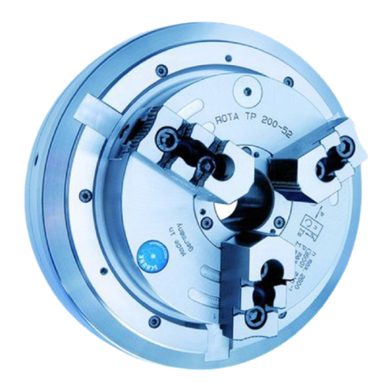
- Page 1 Pneumatic Chuck ROTA TP Assembly and operating manual Translation of the original manual...
- Page 2 Imprint Imprint Copyright: This manual is protected by copyright. The author is SCHUNK GmbH & Co. KG. All rights reserved. Technical changes: We reserve the right to make alterations for the purpose of technical improvement. Document number: 0889071 Version: 06.00 | 07/03/2023 | en...
-
Page 3: Table Of Contents
Table of contents Table of Contents 1 General ..................... 5 About this manual................1.1.1 Presentation of Warning Labels ............. 1.1.2 Applicable documents ..............1.1.3 Sizes..................1.2 Warranty ................... 1.3 Scope of delivery................. 2 Basic safety notes ................2.1 Intended use..................2.2 Not intended use ................ - Page 4 Table of contents 4.2 Functional testing ................27 4.3 Air transmission system ................ 28 4.4 Pilot controlled check valve ..............29 4.5 Clamping or jaw actuation ..............30 4.6 Power Chuck with extended and standard jaw stroke (LH)......31 5 Transport ................... 32 6 Mounting ...................
-
Page 5: General
General 1 General 1.1 About this manual This manual contains important information for a safe and appropriate use of the product. This manual is an integral part of the product and must be kept accessible for the personnel at all times. Before starting work, the personnel must have read and understood this operating manual. -
Page 6: Applicable Documents
Catalog data sheet of the purchased product * Calculation of the jaw centrifugal forces, "Technology" chapter in the lathe chuck catalog * The documents labeled with an asterisk (*) can be downloaded from schunk.com. 1.1.3 Sizes This operating manual applies to the following sizes: ROTA TP 125-26;... -
Page 7: Basic Safety Notes
By conversions, changes, and reworking, e.g. additional threads, holes, or safety devices can impair the functioning or safety of the product or damage it. Structural changes should only be made with the written approval of SCHUNK. 06.00 | ROTA TP | Pneumatic Chuck | en | 0889071... -
Page 8: Spare Parts
Use of unauthorized spare parts Using unauthorized spare parts can endanger personnel and damage the product or cause it to malfunction. Use only original spare parts or spares authorized by SCHUNK. 2.5 Chuck jaws Requirements of the chuck jaws Stored energy can make the product unsafe and poses the danger of serious injuries and considerable material damage. -
Page 9: Environmental And Operating Conditions
Basic safety notes 2.6 Environmental and operating conditions Required ambient conditions and operating conditions Incorrect ambient and operating conditions can make the product unsafe, leading to the risk of serious injuries, considerable material damage and/or a significant reduction to the product's life span. Make sure that the product is used only in the context of its defined application parameters, [/ 17]. -
Page 10: Personal Protective Equipment
Basic safety notes 2.8 Personal protective equipment Use of personal protective equipment Personal protective equipment serves to protect staff against danger which may interfere with their health or safety at work. When working on and with the product, observe the occupational health and safety regulations and wear the required personal protective equipment. -
Page 11: Transport
Basic safety notes 2.10 Transport Handling during transport Incorrect handling during transport may impair the product's safety and cause serious injuries and considerable material damage. When handling heavy weights, use lifting equipment to lift the product and transport it by appropriate means. Secure the product against falling during transportation and handling. -
Page 12: Fundamental Dangers
Basic safety notes 2.13 Fundamental dangers General Observe safety distances. Never deactivate safety devices. Before commissioning the product, take appropriate protective measures to secure the danger zone. Disconnect power sources before installation, modification, maintenance, or calibration. Ensure that no residual energy remains in the system. -
Page 13: Protection Against Dangerous Movements
Basic safety notes 2.13.3 Protection against dangerous movements Unexpected movements Residual energy in the system may cause serious injuries while working with the product. Switch off the energy supply, ensure that no residual energy remains and secure against inadvertent reactivation. Never rely solely on the response of the monitoring function to avert danger. - Page 14 Basic safety notes DANGER Risk of fatal injury to operating personnel due to the workpiece falling down or being flung out in the event of a power failure. In the event of a power failure, the lathe chuck's clamping force may fail immediately and the workpiece may be released in an uncontrolled manner.
- Page 15 Basic safety notes DANGER Possible risk of fatal injury to operating personnel from clothing or hair being caught on the lathe chuck and being dragged into the machine Loose clothing or long hair may become caught on projecting parts of the lathe chuck and be drawn into the machine. The machines and equipment must fulfill the minimum requirements of the EC Machinery Directive;...
- Page 16 Basic safety notes CAUTION Risk of burns due to workpieces with high temperatures. Wear protective gloves when removing the workpieces. Automatic loading is preferred. CAUTION Risk of damages due to incorrect choice of clamping position for chuck jaws on workpiece. If an incorrect clamping position is chosen for the chuck jaws on workpiece, the base and the top jaws may be damaged.
-
Page 17: Technical Data
Technical data 3 Technical data 3.1 Chuck data Size 125-26 160-38 200-52 250-6 315-90 315-10 315-115 LH 350-11 Chuck through bore [mm] Max. clamping force [kN] Max. rotation speed 4200 4200 3800 3500 2500 3000 2200 2200 [min-1] Stroke per jaw [mm] Serration of the jaws 1/16"x90°... -
Page 18: Clamping Force / Speed Diagrams
It is also assumed the chuck is in perfect condition and lubricated with SCHUNK LINOMAX plus special grease . If one or more of these prerequisites is altered, the diagrams will no longer be valid. - Page 19 Technical data Clamping force / speed diagram ROTA TP 160-38 Minimum required clamping force 33% Speed of rotation Clamping force / speed diagram ROTA TP 200-52 Minimum required clamping force 33% Speed of rotation Clamping force / speed diagram ROTA TP 250-68 Minimum required clamping force 33% Speed of rotation...
- Page 20 Technical data Clamping force / speed diagram ROTA TP 315-90 Minimum required clamping force 33% Speed of rotation Clamping force / speed diagram ROTA TP 315-105 Minimum required clamping force 33% Speed of rotation Clamping force / speed diagram ROTA TP 350-115 Minimum required clamping force 33% Speed of rotation...
-
Page 21: Calculations For Clamping Force And Speed
Technical data Clamping force / speed diagram ROTA TP-LH 350-115 Minimum required clamping force 33% Speed of rotation 3.3 Calculations for clamping force and speed Missing information or specifications can be requested from the manufacturer. Legend Total centrifugal force [N] Centrifugal torque of top jaws [Kgm] Effective clamping force [N] Centrifugal torque of base jaws [Kgm]... - Page 22 Technical data (–) for gripping from the outside inwards (+) for gripping from the inside outwards DANGER Risk to life and limb of the operating personnel and significant property damage when the RPM limit is exceeded! With gripping from the outside inwards, and with increasing RPM, the effective clamping force is reduced by the magnitude of the increasing centrifugal force (the forces are opposed).
- Page 23 Technical data (+) for gripping from the outside inwards (–) for gripping from the inside outwards NOTICE This calculated force must not be larger than the maximum clamping force ΣS engraved on the lathe chuck. See also "Lathe chuck data" table } 3.1 [/ 17] From the above formula it is evident that the sum of the effective clamping force F...
-
Page 24: Calculation Example: Required Initial Clamping Force For A Given Speed
Technical data 3.3.2 Calculation example: required initial clamping force for a given speed Required initial clamping force F for a given RPM n The following data is known for the machining job: Gripping from the outside in (application-specific) Machining force F = 3000 N (application-specific) max. -
Page 25: Calculation Of The Permissible Speed In Case Of A Given Initial Clamping Force
Technical data The total centrifugal force can now be calculated: Initial clamping force during shutdown that was sought: 3.3.3 Calculation of the permissible speed in case of a given initial clamping force Calculation of the permissible RPM n in case of a given initial perm clamping force F The following formula can be used to calculate the permissible... -
Page 26: Grades Of Accuracy
Technical data 3.4 Grades of Accuracy Tolerances for radial and axial run-out accuracy correspond to the Technical Supply Terms for lathe chucks as per DIN ISO 3442-3. 3.5 Permissible imbalance The ROTA TP in ungreased state without T-nuts and top jaws corresponds to the balancing quality class 6.3 (according to DIN ISO 21940-11). -
Page 27: Function
Function 4 Function The item numbers specified for the corresponding individual components relate to chapter drawings.} 9 [/ 53] 4.1 Principle of Operation The problem of air supply was solved by a stationary distributor ring with profile ring seals arranged therein. Openings in the two elastic radially deformable profile seals allow the compressed air to flow through a non-return valve to one of the two pressure chambers. -
Page 28: Air Transmission System
Function 4.3 Air transmission system Air transfer takes place only when the headstock spindle is at a standstill, via profile seals provided radially in the distributor ring. The profile seal is designed so that the outer upper section of the surface is larger than the surface of the openings. Upon pressurization the difference in surface area exerts a radial force on the profile seal in the ring-shaped chamber of the distributor ring, resulting in optimal static sealing of the profile seal at the... -
Page 29: Pilot Controlled Check Valve
Function 4.4 Pilot controlled check valve from cylinder chamber II to cylinder chamber I Locking screw from distributor ring ventilated locking to distributor ring vented locking pistons (profile seal) pistons (profile seal) The pilot-controlled check valve is an intrinsically sealed unit, and comprises a valve body plus two locking pistons. -
Page 30: Clamping Or Jaw Actuation
Function 4.5 Clamping or jaw actuation Base jaw Piston impact when clamping Force diversion Axial force Piston guide on guide bushing Wedge hook on piston Piston collar Piston bore Piston impact hole when unclamping Piston cover Central jaw drive of the front-end power chuck All three base jaws are centrically driven by a piston with a collar. -
Page 31: Power Chuck With Extended And Standard Jaw Stroke (Lh)
Function 4.6 Power Chuck with extended and standard jaw stroke (LH) Lathe chucks with dual stroke system (LH-serie) are not allowed to be used for I.D. clamping. Moreover, no workpieces are allowed to be clamped on the fast jaw stroke, since due to the long jaw strokes the resulting clamping forces are lower (1). -
Page 32: Transport
Transport 5 Transport DANGER Risk of fatal injury from suspended loads! Falling loads are sure to cause serious injuries and even death. Use suitable lifting equipment. Secure the product to prevent it from falling. Stand clear of suspended loads and do not step within their swiveling range. -
Page 33: Mounting
Mounting 6 Mounting 6.1 Installing and connecting WARNING Risk of injury due to unexpected movements! If the power supply is switched on or residual energy remains in the system, components can move unexpectedly and cause serious injuries. Before starting any work on the product: Switch off the power supply and secure against restarting. -
Page 34: Inclusion
Mounting 6.2 Inclusion For ROTA TP 125 / Z up to 350 / Z lathe chuck types, a normal intermediate flange must be placed on the spindle head. Using 6 pin screws M12 x 40 (sizes 160 - 350), the rear flange side of the front of the power chuck which has been turned free is screwed »across corners«... -
Page 35: Distributor Ring
Mounting 6.3 Distributor ring The distributor ring of the front-mounted power chuck model ROTA TP 125 – 350 and TP-LH 315 – 350 is supplied with 2 possible means of fastening as standard. 6.3.1 Distributor ring: normal fastening The distributor ring is automatically centered with the chuck body by a plastic centering sleeve (Hostaform C). - Page 36 Mounting ONLY use flexible cable connections If the plastic centering sleeve of the distributor ring becomes worn slightly at the weight-loaded upper point of contact with the chuck body over time, it can be turned further by one third by removing the three hexagon socket screws. The three hexagon socket screws hold the two parts of the distributor ring and the plastic centering sleeve together.
-
Page 37: Stationary Mounting Of The Distributor Ring
Mounting Sensor E-connection System pressure switch to evaluation units from pressure for minimum pressure switch Spindle start or tensioning not E-connection enabled in case of negative deviation from magnetic valve Clamping Air maintenance unit pressure consisting of filter, display water separator and oiler Connections: G1/8 (ROTA TP 125) -
Page 38: Mounting With Bracket
Mounting distributor ring is to be fastened but is equipped standard with the centering sleeve, the centering sleeve must be replaced with the enclosed spacer ring. 6.3.3 Mounting with bracket First, the lathe chuck is installed onto the machine spindle with the loosely attached distributor ring and the distributor ring is aligned flush with the stepped front side of the chuck. - Page 39 Mounting Mounting surface Mounting surface on distributor ring on spindle box Spacer ring 06.00 | ROTA TP | Pneumatic Chuck | en | 0889071...
-
Page 40: Mounting With 2-Part Clamping Ring (D.r.m.b.)
Mounting 6.3.4 Mounting with 2-part clamping ring (D.R.M.B.) The distributor ring can be clamped onto a rigid collar on the machine (at least 8 mm wide) using a two-piece clamping ring. The distributor ring is clamped onto this collar by two screws. The height of the clamping ring is designed according to the "Bracket Mounting"... - Page 41 Mounting Distributor ring fixing with 2-piece clamping ring 06.00 | ROTA TP | Pneumatic Chuck | en | 0889071...
- Page 42 Mounting Spacer ring Centering ring Distributor ring Spacer ring,} 6.3.3 [/ 38] Centering ring, } 6.3.2 [/ 37] 06.00 | ROTA TP | Pneumatic Chuck | en | 0889071...
-
Page 43: Commissioning And Maintenance
Facing or skimming of the front-end power chuck is not permitted. Drilling of the chuck on the front face side may be performed only in accordance with the drilling patterns on the SCHUNK dimension sheets. 06.00 | ROTA TP | Pneumatic Chuck | en | 0889071... -
Page 44: Maintenance
Commissioning and maintenance 7.2 Maintenance A type WEH maintenance unit, consisting of filter, water separator, and oiler, must be connected upstream of the power chuck. The air enriched with oil supplies all sliding parts of the cylinder chamber with an oil film. The oil level of the oil tank must be checked daily, and oil must be added if necessary. - Page 45 Commissioning and maintenance Mounted directly from front: 2 bore Required distance for removing the holes Ø L, depth C4 container Lateral mounting with 2 retaining Automatic condensate drain can be brackets (accessories) connected by means of a hose with Ø 6 inside Protective metal cage with container Pressure gauge, Ø...
- Page 46 Commissioning and maintenance Flow rate characteristic curves and pressure drops Flow rate Cleaning and lubrication of the lathe chuck The uniform clamping force, accuracy, and life span of the chuck depend greatly on regular cleaning and sufficient lubrication. Rust, scale, casting dust, and chips produce friction and reduce motion.
-
Page 47: Maintenance Intervals
Commissioning and maintenance be used before full maintenance is required depends on the level of dirt it accumulates and the clamping frequency. As such, it is not possible to specify a generally applicable rule for this. Please regularly check the lathe chuck for tightness by applying a clamping force tester over a longer period of time (>... -
Page 48: Disassembly
Commissioning and maintenance 7.5 Disassembly Unscrew both pneumatic swivelling elbow screw-fittings from the distributor ring, remove front-mounted power chuck from spindle head. After unscrewing the 3 hexagon socket head screws (item 38) in 3 pieces (item 9, 11, 12), remove the distributor ring backwards from the chuck. -
Page 49: Assembly
Commissioning and maintenance position and thus the same true running accuracy is achieved during assembly. The hardened base jaws simply have 1, 2, or 3 notches for marking the T-slots. Remove all O-rings of the chuck and the profile seals (item 66) at the distributor ring. - Page 50 Commissioning and maintenance Lubricate valve system (item 18) and valve bore hole with oil, install and close with plug-in screw and O-ring (item 3). Note: All parts of the ROTA TP-type front-end power chuck are lightweight. As such, hard hammer blows should never be used during assembly.
-
Page 51: Spare Parts
Spare parts 8 Spare parts When ordering spare parts, it is imperative to specify the type, size and above all the manufacturing no of the chuck. Seals, sealing elements, screw connections, springs, bearings, screws and wiper bars plus parts coming into contact with the workpiece are not covered by the warranty. - Page 52 Spare parts Copper seal Profile seal Bracket Eye bolt 06.00 | ROTA TP | Pneumatic Chuck | en | 0889071...
-
Page 53: Assembly Drawings
Assembly drawings 9 Assembly drawings ROTA TP with standardized cover 06.00 | ROTA TP | Pneumatic Chuck | en | 0889071... -
Page 54: Translation Of The Original Declaration Of Incorporation
Directive 2006/42/EG, Annex II, Part 1.B of the European Parliament and of the Council on machinery. Hersteller/ H.-D. SCHUNK GmbH & Co. Spanntechnik KG Inverkehrbringer Lothringer Str. 23 D-88512 Mengen We hereby declare that on the date of the declaration the following partly completed machine complied with all basic safety and health regulations found in the directive 2006/42/EC of the European Parliament and of the Council on machinery. -
Page 55: Appendix On Declaration Of Incorporation, As Per 2006/42/Ec, Annex Ii, No. 1 B
Appendix on Declaration of Incorporation, as per 2006/42/EC, Annex II, No. 1 B 11 Appendix on Declaration of Incorporation, as per 2006/42/EC, Annex II, No. 1 B 1. Description of the basic safety and health protection requirements, as per 2006/42/EC, Annex I, that apply to and are fulfilled for the scope of the partly completed machinery: Product designation Type designation... - Page 56 Appendix on Declaration of Incorporation, as per 2006/42/EC, Annex II, No. 1 B Protection against mechanical hazards 1.3.6 Risks related to variations in operating conditions 1.3.7 Risks related to moving parts 1.3.8 Choice of protection against risks arising from moving parts 1.3.8.1 Moving transmission parts 1.3.8.2 Moving parts involved in the process 1.3.9...
- Page 57 Appendix on Declaration of Incorporation, as per 2006/42/EC, Annex II, No. 1 B Maintenance 1.6.5 Cleaning of internal parts Information 1.7.1 Information and warnings on the machinery 1.7.1.1 Information and information devices 1.7.1.2 Warning devices 1.7.2 Warning of residual risks 1.7.3 Marking of machinery 1.7.4...
- Page 58 06.00 | ROTA TP | Pneumatic Chuck | | 0889071...
- Page 59 06.00 | ROTA TP | Pneumatic Chuck | | 0889071...
- Page 60 H.-D. SCHUNK GmbH & Co. Spanntechnik KG Lothringer Str. 23 D-88512 Mengen Tel. +49-7572-7614-0 Fax +49-7572-7614-1099 info@de.schunk.com schunk.com Folgen Sie uns I Follow us Wir drucken nachhaltig I We print sustainable...
Need help?
Do you have a question about the ROTA TP Series and is the answer not in the manual?
Questions and answers