
Subscribe to Our Youtube Channel
Related Manuals for SCHUNK ROTA NCX


Summary of Contents for SCHUNK ROTA NCX
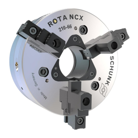
- Page 1 Translation of Original Operating Manual Power chucks ROTA NCX Assembly and Operating Manual Superior Clamping and Gripping...
- Page 2 Imprint Copyright: This manual is protected by copyright. The author is SCHUNK GmbH & Co. KG. All rights reserved. Any reproduction, processing, distribution (making available to third parties), translation or other usage - even excerpts - of the manual is especially prohibited and requires our written approval.
-
Page 3: Table Of Contents
Table of contents Table of contents 1 General ........................5 1.1 About this manual ....................5 1.1.1 Presentation of Warning Labels ..............5 1.1.2 Applicable documents ................... 6 1.1.3 Sizes ....................... 6 1.2 Warranty ........................6 1.3 Scope of delivery ...................... 6 2 Basic safety notes .................... - Page 4 Table of contents 5 Assembly ......................... 29 5.1 Installing and connecting ..................29 5.2 Finish turning the center sleeve blank ..............29 5.3 Checking the chuck mounting ................30 5.4 Mounting the lathe chuck onto the machine spindle ..........30 6 Function and handling .....................
-
Page 5: General
General General About this manual This manual contains important information for a safe and appropriate use of the product. This manual is an integral part of the product and must be kept accessible for the personnel at all times. Before starting work, the personnel must have read and understood this operating manual. -
Page 6: Applicable Documents
The documents marked with an asterisk (*) can be downloaded on our homepage schunk.com 1.1.3 Sizes This operating manual applies to the following sizes: • ROTA NCX 165-53 • ROTA NCX 210-66 • ROTA NCX 260-81 • ROTA NCX 315-106 Warranty... -
Page 7: Basic Safety Notes
Basic safety notes Basic safety notes Intended use This product is intended for clamping workpieces on machine tools and other suitable technical devices. • The product may only be used within the scope of its technical data, ( 3, Page 19). -
Page 8: Constructional Changes
Use of unauthorized spare parts Using unauthorized spare parts can endanger personnel and damage the product or cause it to malfunction. • Use only original spare parts or spares authorized by SCHUNK. Chuck jaws Requirements of the chuck jaws Stored energy can make the product unsafe and risk the danger of serious injuries and considerable material damage. -
Page 9: Environmental And Operating Conditions
Basic safety notes • Screw the jaw mounting screws into the bore holes furthest apart. • The jaw fastening screws must be replaced if they show any signs of wear or damage. Only use screws with a quality of 12.9. Environmental and operating conditions Required ambient conditions and operating conditions Incorrect ambient and operating conditions can make the product... -
Page 10: Personnel Qualification
Basic safety notes Personnel qualification Inadequate qualifications of the personnel If the personnel working with the product is not sufficiently qualified, the result may be serious injuries and significant property damage. • All work may only be performed by qualified personnel. •... -
Page 11: Personal Protective Equipment
Basic safety notes Personal protective equipment Use of personal protective equipment Personal protective equipment serves to protect staff against danger which may interfere with their health or safety at work. • When working on and with the product, observe the occupational health and safety regulations and wear the required personal protective equipment. -
Page 12: Transport
Basic safety notes 2.10 Transport Handling during transport Incorrect handling during transport may impair the product's safety and cause serious injuries and considerable material damage. • When handling heavy weights, use lifting equipment to lift the product and transport it by appropriate means. •... -
Page 13: Fundamental Dangers
Basic safety notes 2.13 Fundamental dangers General • Observe safety distances. • Never deactivate safety devices. • Before commissioning the product, take appropriate protective measures to secure the danger zone. • Disconnect power sources before installation, modification, maintenance, or calibration. Ensure that no residual energy remains in the system. -
Page 14: Protection During Commissioning And Operation
Basic safety notes 2.13.2 Protection during commissioning and operation Falling or violently ejected components Falling and violently ejected components can cause serious injuries and even death. • Take appropriate protective measures to secure the danger zone. • Never step into the danger zone during operation. 2.13.3 Protection against dangerous movements Unexpected movements... -
Page 15: Notes On Particular Risks
Basic safety notes 2.13.4 Notes on particular risks DANGER Risk of fatal injury from suspended loads! Falling loads can cause serious injuries and even death. • Stand clear of suspended loads and do not step within their swiveling range. • Never move loads without supervision. •... - Page 16 Basic safety notes DANGER Possible risk of fatal injury to operating personnel if a jaw breaks or if the lathe chuck fails because the technical data have been exceeded and a workpiece is released or parts fly off • The technical data specified by the manufacturer for using the lathe chuck must never be exceeded.
- Page 17 Basic safety notes CAUTION Danger of limbs being crushed by opening and closing of the chuck jaws during manual loading and unloading or when replacing moving parts. • Do not reach between the jaws. • Wear safety gloves. • Observe the safety and accident prevention regulations during operation of the chuck, especially in connection with machining centers and other technical equipment.
- Page 18 Basic safety notes CAUTION Hazard from vibration due to imbalanced rotating parts and noise generation. Physical and mental strains due to imbalanced workpieces and noise during the machining process on the clamped and rotating workpiece. • Ensure the chuck's axial and concentric runout. •...
-
Page 19: Technical Data
Examples of calculation can be [kgm] found in the "Technology" chapter of the SCHUNK lathe chuck catalog and in the "Chuck jaws in special design/technology" chapter of the SCHUNK chuck jaws catalog. These catalogs can be downloaded from schunk.com. -
Page 20: Clamping Force / Speed Diagrams
For this, the maximum actuating force was applied and the jaws were set flush with the outer diameter of the chuck. The chuck is in perfect condition and lubricated with SCHUNK LINOMAX plus special grease. If one or more of these prerequisites is modified, the graphs will no longer be valid. - Page 21 Technical data Clamping force/RPM graph for ROTA NCX 210-66 Clamping force/RPM graph for ROTA NCX 260-81 Clamping force/RPM graph for ROTA NCX 315-106 03.00|0889148_ROTA NCX |en...
-
Page 22: Calculations For Clamping Force And Speed
Technical data Calculations for clamping force and speed Missing information or specifications can be requested from the manufacturer. Legend Total centrifugal force [N] Centrifugal torque of top jaws [Nm] Effective clamping force [N] Centrifugal torque of base jaws [Nm] Minimum required clamping force Speed [rpm] spmin Initial clamping force [N]... - Page 23 Technical data DANGER Risk to life and limb of the operating personnel and significant property damage when the RPM limit is exceeded! With gripping from the outside inwards, and with increasing RPM, the effective clamping force is reduced by the magnitude of the increasing centrifugal force (the forces are opposed).
- Page 24 Technical data CAUTION This calculated force must not be larger than the maximum clamping force ΣS engraved on the chuck. See also "Chuck data" table ( 3.1, Page 19) From the above formula it is evident that the sum of the effective clamping force F and the total centrifugal force F is multiplied by...
-
Page 25: Calculation Example: Required Initial Clamping Force For A Given Speed
Technical data 3.3.2 Calculation example: required initial clamping force for a given speed Required initial clamping force F for a given speed n The following data is known for the machining job: • Gripping from the outside in (application-specific) • Machining force F = 3000 N (application-specific) •... -
Page 26: Calculation Of The Permissible Speed In Case Of A Given Initial Clamping Force
Technical data The chuck has 3 jaws, the total centrifugal torque is: The total centrifugal force can now be calculated: Initial clamping force during shutdown that was sought: Calculation of the permissible speed in case of a given initial 3.3.3 clamping force Calculation of the permissible speed n in case of a given initial... -
Page 27: Grades Of Accuracy
Technical Supply Terms for lathe chucks as per DIN ISO 3442-3. Permissible imbalance DIN ISO 21940-11 The ROTA NCX in ungreased state without chuck jaws corresponds to the balancing quality class 6.3 (according to DIN ISO 21940-11). Residual imbalance risks may arise due to insufficient rotation compensation being achieved (see DIN EN 1550 6.2 e). -
Page 28: Torques Per Screw
Torques per screw Torques per screw Tightening torques for mounting screws used to clamp the chuck on lathes or other suitable technical equipment (screw quality 10.9) Screw size M6 M8 M10 M12 M14 M16 M18 M20 M22 M24 M27 M30 Admissible torque 120 160 200 290 400 500 1050 1500 (Nm) -
Page 29: Assembly
(item 11) into the piston (item 3) and screw in the retainer ring (item 10). Maximum internal thread for center sleeve blanks: Chuck size ROTA NCX 165 ROTA NCX 210 ROTA NCX 260 ROTA NCX 315 Max. thread M60 x 2 M75 x 2... -
Page 30: Checking The Chuck Mounting
Assembly Checking the chuck mounting • Check the machine spindle head or the ready-machined inter- mediate flange for radial and axial run-out. The permissible limit is 0.005 mm as per DIN 6386-1. • The contact surface must be chamfered and clean at the bores. Mounting the lathe chuck onto the machine spindle •... - Page 31 Lubricating before commissioning the lathe chuck Before commissioning, move the chuck into the open position. Using a high-pressure grease press, press SCHUNK special grease LINOMAX plus into the lubricating nipple every 3 strokes. For optimum grease distribution and to achieve the maximum clamping force, close and open the chuck several times over the entire clamping stroke.
-
Page 32: Function And Handling
Function and handling Function and handling The item numbers specified for the corresponding individual components relate to chapter drawings.( 9, Page 42) Function of the chuck The quick-change power chuck is actuated using rotating solid or open-center hydraulic cylinders. The axial tensile or pressure forces are converted to the radial jaw clamping force via wedge bars positioned tangentially to the chuck body. -
Page 33: Base Jaw Position
Function and handling The jaw change key is locked so long as the chuck jaws have not been moved into the functional area! The functional area means that the base jaw is engaged by the serration of the wedge bar. CAUTION The jaw-change bolt (item 6) may only be turned when the chuck is in open position. -
Page 34: Change Or Supplement Of Jaws
Function and handling Change or supplement of jaws Jaws for highest repeatability must be bored and ground in the chuck under clamping pressure. • When boring and grinding it is important that the boring ring or the boring bolts are clamped by the top jaws – and not by the base jaws. - Page 35 Function and handling DANGER Risk of fatal injury to operating personnel if the top speed is exceeded, resulting in workpiece loss and parts flying off! • A reliable speed limiter must be installed in the machine tool or technical equipment and proof must be provided that the speed limiter is effective! 03.00|0889148_ROTA NCX |en...
-
Page 36: Maintenance
(A - see Fig. "Lubrication") using a high-pressure grease gun with two to six strokes (depending on the chuck side) of SCHUNK LINO MAX special grease at each nipple. For optimum grease distribution, the clamping piston must travel the entire clamping stroke several times after lubrication. -
Page 37: Maintenance Intervals
If a jaw is removed from the jaw guidance, turn the release key counterclockwise.The monitoring pin (item 6) must exit from the wedge bar (item 5). If this is not the case, the chuck must be disassembled and cleaned. Only original SCHUNK spare parts may be used. 03.00|0889148_ROTA NCX |en... -
Page 38: Disassembling And Assembling The Chuck
Maintenance Disassembling and assembling the chuck The lathe chuck may only be disassembled once it has been uninstalled (see chapter "Mounting the lathe chuck" ( 5, Page 29)). • Move the jaws to the outermost position permissible and leave them in the chuck, move the piston to the front end position (chuck open). - Page 39 (item 33) on the wrench and screw it in backwards. Determine the depth of engagement together with chuck body (pos. 1) and base jaws (pos. 2). Only original SCHUNK spare parts may be used. The lathe chuck is assembled in the same way but in the reverse order.
-
Page 40: Chuck Mounts And Spare Parts
Chuck mounts and Spare parts Chuck mounts and Spare parts Chuck mounts SCHUNK type Chuck mount ID No. ROTA NCX 165-53 DIN ISO 702-4-No. 5 (Z140) 0800800 DIN ISO 702-1-A5 0800801 ROTA NCX 210-66 DIN ISO 702-4-No. 6 (Z170) 0800810... - Page 41 Chuck mounts and Spare parts Item Designation Quantity Steel ball for jaw-change bolt Steel ball for wedge bar Screw Screw Screw Spring Lubrication nipple Spring-loaded pressure pieces 3 (size 315: 6) O-ring Steel ball 3 (size 315: 0) Spring 3 (size 315: 0) O-ring 3 (size 315: 0) O-ring...
-
Page 42: Drawing
Drawing Drawing 03.00|0889148_ROTA NCX |en... -
Page 43: Translation Of The Original Declaration Of Incorporation
Directive 2006/42/EG, Annex II, Part 1.B of the European Parliament and of the Council on machinery. Manufacturer/ H.-D. SCHUNK GmbH & Co. Spanntechnik KG Distributor Lothringer Str. 23 D-88512 Mengen We hereby declare that on the date of the declaration the following partly completed machine complied with all basic safety and health regulations found in the directive 2006/42/EC of the European Parliament and of the Council on machinery. -
Page 44: Appendix On Declaration Of Incorporation, As Per 2006/42/Ec, Annex Ii, No. 1 B
Appendix on Declaration of Incorporation, as per 2006/42/EC, annex II, No. 1 B Appendix on Declaration of Incorporation, as per 2006/42/EC, annex II, No. 1 B 1. Description of the basic safety and health protection requirements, as per 2006/42/EC, annex I, that apply to and are fulfilled for the scope of the partly completed machine: Product designation Power Lathe Chuck with Quick Jaw Change System... - Page 45 Appendix on Declaration of Incorporation, as per 2006/42/EC, annex II, No. 1 B Risks due to other hazards 1.5.1 Electricity supply 1.5.2 Static electricity 1.5.3 Energy supply other than electricity 1.5.4 Errors of fitting 1.5.5 Extreme temperatures 1.45.6 Fire 1.5.7 Explosion 1.5.8 Noise...
Need help?
Do you have a question about the ROTA NCX and is the answer not in the manual?
Questions and answers