Table of Contents
Advertisement
Quick Links
Note :
The PL-2 differs from the PL-1 only in that it
includes an adapter card that fits into the DR/iDR-
switch logic output connector plug. This routes the
+10V reference voltage via resistors to the open
collector '+' pins. You wire the '-' pins to the PL-2
connectors. The PL-1 does not include the adapter
card.
This
product
complies
Electromagnetic Compatibility directives 89/336/EEC &
92/31/EEC.
NOTE:
Any changes or modifications to the
equipment not approved by Allen & Heath could void
the compliance of the equipment. Whilst we believe
the information in this guide to be reliable we do not
assume responsibility for inaccuracies. We also reserve
the right to make changes in the interest of further
product development.
PL-2 User Guide AP5080 Issue 1
Copyright© 2003 Allen & Heath Ltd. All rights reserved.
PL-2 User Guide AP5080
PL-2 Wall Plate for DR/iDR-switch
USER GUIDE
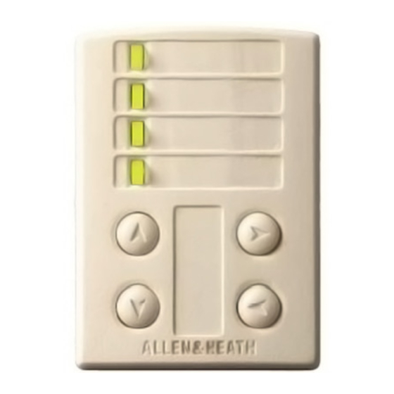
Introduction
the Allen & Heath DR-switch or iDR-switch logic expanders. It is a wall plate or
furniture mounted module comprising plastic control panel and attached circuit
assembly. It can be mounted in a single unit wall box using a standard face
plate (UK, EU or US version supplied).
(AA5029) or US (AA5030) plate is supplied.
DR/iDR-switch rear panel SWITCH INPUTS and LOGIC outputs ports. The
number of PL-2 units which may be connected is determined by the number of
remote switch and logic output lines from the DR/iDR system and how many
you wire to each PL unit. The wall plate switch and indicator functions are
programmed using the Allen & Heath WinDR (DR-switch) or iDR System
Manager (iDR-switch) software. Space is provided on the control panel for
custom labelling. The following combination of controls makes the PL-2 ideal
as a wall mounted room remote controller in installed audio systems. The
installer can program the unit so that the non-technical operator has local
control using pre-programmed switches LEDs.
4 switches For DR-switch they can be assigned for level up or down control
(input, output, or crosspoint), mute toggle or patch recall. For iDR-switch they
can be assigned for level up or down control (input, output, crosspoint or
group), mute toggle, polarity toggle, audio monitor select, or patch recall. 4
LED indicators For DR-switch they can be assigned to display input or output
channel mute status, or as patch related static indicators. For iDR-switch they
can be assigned as audio meters (choice of 8 points in the signal path), mute
status, polarity status, or as patch related static display. Each can be wired to
display either red or green. Two DR/iDR-switch outputs can be used to switch
one LED to red, green or yellow. Custom labels Recessed areas are provided
for fitting custom adhesive labels. Recommended maximum sizes are 6x26mm
and 26x9mm (h x w).
with
the
European
The PL-2 is a remote control device available for use with
A pre-cut brushed aluminium EU
IMPORTANT :
Observe the local standards which may apply
to the installation regarding the grade of cable and
installation methods.
To ensure operator safety ensure that any
exposed metal face plates are correctly bonded to
ground. Do not install the equipment where it is
subject to moisture, heat or vibration.
Connect this equipment to the Allen & Heath
DR-switch or iDR-switch only. It is very important to
test for correct wiring and installation before
switching the equipment on.
The DR/iDR-switch provides opto-isolated
contact closure switch inputs and open collector
logic outputs.
How these are wired to external
equipment is the responsibility of the installer.
Details are provided here for wiring to the PL-2 wall
plate. Allen & Heath do not assume responsibility
for any damage done to the equipment due to
incorrect or faulty installation.
The PL-2 interfaces with the
AP5080
1
Advertisement
Table of Contents

Related Manuals for ALLEN & HEATH PL-2


Summary of Contents for ALLEN & HEATH PL-2
- Page 1 The PL-2 interfaces with the DR/iDR-switch rear panel SWITCH INPUTS and LOGIC outputs ports. The number of PL-2 units which may be connected is determined by the number of remote switch and logic output lines from the DR/iDR system and how many you wire to each PL unit.
- Page 2 Connect required position. Reassemble the module. each DR/iDR-switch SWITCH INPUT pin to the required PL-2 SW terminal. Wire the DR/iDR-switch G (ground) pin to the PL-2 0V common terminal. Connect the LOGIC OUTPUT – (emitter) pins to the required R or G LED terminal as shown below, and 0V common to the G pin.
Need help?
Do you have a question about the PL-2 and is the answer not in the manual?
Questions and answers