Table of Contents
Advertisement
Quick Links
Advertisement
Table of Contents

Subscribe to Our Youtube Channel
Related Manuals for CKD GCKW Series


Summary of Contents for CKD GCKW Series
- Page 1 GCKW Series Electric Actuator Gripper 3 Finger Type INSTRUCTION MANUAL Read this Instruction Manual before using the product. In particular, read the safety notes carefully. Keep this Instruction Manual safe for use at any time. 2023-02-21 SM-A69875-A/2...
-
Page 2: Preface
PREFACE Thank you for purchasing CKD's "GCKW Series" electric actuator. The GCKW series (gripper three-finger type) can support a wide variety of workpieces because of multi-point positioning and allows the speed and pressing force to be set, thus being capable of soft handling without giving an impact to a workpiece. -
Page 3: Safety Information
SAFETY INFORMATION When designing and manufacturing any device incorporating the product, the manufacturer has an obligation to ensure that the device is safe. To that end, make sure that the safety of the machine mechanism of the device and the electric system that controls such mechanism is ensured. - Page 4 < Warning symbol type > A general purpose mark A mark that prohibits touching indicating prohibited (not equipment. allowed) actions. A general purpose mark A mark that prohibits the act of indicating the danger such as putting a finger. electric shock and burn. A mark indicating the danger A general purpose mark that occurs when an automatic...
-
Page 5: Precautions On Product Use
Precautions on Product Use DANGER Do not use this product for the following applications. Medical equipment pertaining to sustainment and management of human life and body Mechanism and mechanical device for transferring and transporting people Critical parts for securing safety in a mechanical device WARNING Never modify or implement additional processing to the product. -
Page 6: Table Of Contents
CONTENTS PREFACE ......................2 SAFETY INFORMATION ..................3 Precautions on Product Use ..................5 CONTENTS ......................6 1. PRODUCT OVERVIEW ..................7 System Structure ..................... 7 Instruction Manuals Related to This Product ............9 Part Name ......................10 Model Number Indication ..................11 2. -
Page 7: Product Overview
PRODUCT OVERVIEW System Structure Connect the GCKW series to an ECG-B series controller. System structure Supplied by the customer Surge protector Controller ECG-B series Ferrite core Ferrite core I/O cable Ferrite core For power supply USB cable (mini-B) Noise filter... - Page 8 Of the items in the system configuration, the following can be purchased from us. Component Product name/Model no. This product Actuator GCKW series Accessories Motor/encoder relay cable EA-CBLME2-□□□ Controller ECG-B Series Power supply connector DFMC1,5/3-STF-3,5 (PHOENIX CONTACT) Sold separately I/O cable EA-CBLNP2-□□...
-
Page 9: Instruction Manuals Related To This Product
SM-A27752 FLSH-G series ECG series CC-Link specifications SM-A40842 FLCR-G series SM-A40831 ECG series SM-A40845 IO-Link specifications FGRC-G series SM-A40832 SM-A69875 (this Instruction Manual) ECG series GCKW series EtherCAT specifications SM-A40833 ECG series EtherNet/IP specifications Setting software SM-A11147 S-Tools 2023-02-21 SM-A69875-A/2... -
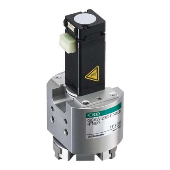
Page 10: Part Name
Part Name Motor Body Finger Pullout cable 2023-02-21 SM-A69875-A/2... -
Page 11: Model Number Indication
Model Number Indication ⚫ Connect this product to an ECG-B Series controller. It does not work when connected to other controllers such as ECG-A and ECR Series controllers. Actuator Motor/encoder Size Connector take-out relay cable direction Not included Front Applicable Fixed cable 1 Side controller... - Page 12 Motor/encoder Connector take-out Size relay cable direction Not included Front Applicable Fixed cable 1 Side controller Front For ECG Fixed cable 3 Side Screw lead Fixed cable 5 1.5 mm Fixed cable 10 Stroke length 4 mm Movable cable (2 mm for one side) Encoder Movable cable Incremental...
- Page 13 Motor/encoder Connector take-out Size relay cable direction Not included Front Applicable Fixed cable 1 Side controller For ECG Fixed cable 3 Front Screw lead Side Fixed cable 5 1.5 mm Fixed cable 10 Stroke length 6 mm Movable cable (3 mm for one side) Encoder Movable cable Connector take-out...
- Page 14 Motor/encoder relay cable (fixed/movable) ◼ Motor and encoder relay cable model number system (ECG-B series) EA-CBLME2- Cable type Cable length Fixed cable Movable cable 10 m ◼ Motor/encoder relay cable external dimensions (ECG-B series) Actuator side Controller side L (Cable length is according to the model number.) 2023-02-21 SM-A69875-A/2...
-
Page 15: Installation
INSTALLATION DANGER Do not use the product in a place where dangerous substances such as ignitable, inflammable, or explosive materials are present. A fire, ignition, or explosion may occur. Do not work with wet hands. Doing so may cause electric shock. Since the control power supply and power supply are not insulated, do not connect the + side and the −... - Page 16 WARNING Do not install the product to a combustible material. Installing it on combustible materials or near combustible materials may cause a fire. Do not place heavy objects on cables or pinch them. If the cable sheath is torn or excessive stress is applied, it may cause poor continuity or deterioration of insulation.
- Page 17 WARNING Design a safety circuit or safety device so that if the machine stops due to a system abnormality such as an emergency stop or a power failure, the equipment will not be damaged or personal injury will not occur. Check the wiring of the product with this Instruction Manual or the related instruction manual to ensure that there are no wiring errors or loose connectors.
- Page 18 CAUTION Do not use the product in an environment where a strong magnetic field occurs. A malfunction may occur. Do not perform a withstand voltage test or an insulation resistance test on a device with the product installed. Due to the circuit design, the product may be damaged if a withstand voltage test or an insulation resistance test is performed on the device with the product installed.
- Page 19 CAUTION When performing electric welding to the equipment to which the product is installed, remove all the frame ground connections of the product. If electric welding is performed with the frame ground connected, the product may be damaged due to welding current, excessive high voltage during welding, or surge voltage.
- Page 20 CAUTION Install the product in a way that it is not subjected to twisting or bending force. Before adjusting the gain, firmly fix the actuator body to the rigid equipment. When using positioning holes, make sure to use pins having the size that does not require press-fitting.
-
Page 21: Installation Environment
Installation Environment Before storing or using the product, check the ambient temperature and atmosphere specified in the product specifications. Use the product at an ambient temperature between 0°C and 40°C. Ventilate if heat can become trapped. Use the product at an ambient humidity between 35% and 80% RH. Do not use the product in a place where condensation occurs. -
Page 22: Unpacking
Unpacking CAUTION Heavy products shall not be carried by a worker alone. Never ride on the packaging. Do not place heavy items or items with concentrated loads that may deform the packaging. Do not apply excessive force to any part of the product. Pay sufficient attention to avoid an impact such as dropping during transportation and handling. -
Page 23: Installing
Installing Actuator CAUTION Do not allow excessive shock or moment to act on the actuator. A malfunction or damage may occur. The flatness of the mounting surface of the body should be 0.02 mm or less. Do not apply twisting or bending force to the product. ... - Page 24 Finger CAUTION When mounting the attachment to the finger, take into consideration the effects exerted on the hand body and perform tightening while providing support using a tool such as a spanner so to prevent the finger from being distorted. ...
-
Page 25: Usage
USAGE DANGER Do not enter the operating range while the actuator can operate. An injury may occur. Do not work with wet hands. Doing so may cause electric shock. WARNING Do not climb on the product or put things on it. ... - Page 26 CAUTION When the controller and actuator are connected with a cable, do not move the actuator moving part by external force except for manual operation. A malfunction or damage may occur due to regenerative currents. Do not apply external force to the actuator during the home position return operation.
- Page 27 CAUTION When changing the combination of the actuator and controller, be sure to check the program and parameters before operating them. An accident may occur. Use the actuator so that no impact is applied to the moving part. Since the product life varies depending on the transfer load, etc., set it with sufficient margin.
- Page 28 ⚫ Repeatability refers to the displacement of the finger stop position when clamping and unclamping are repeated under the same conditions. The same conditions include hand fixing and use of the same attachment, as described below. <Conditions> ◎ Attachment size, shape, and weight ◎...
-
Page 29: Using The Controller
Using the Controller For how to use the controller and S-Tools, refer to the instruction manual for each product. Refer to “1.2Instruction Manuals Related to This Product” for the instruction manual numbers CAUTION Do not use a controller with an old software version. ... -
Page 30: Manual Operation
Manual Operation CAUTION Do not apply excessive torque to the manual operation plate. An operation fault or damage may occur. Before performing manual operation, make sure that the servo is turned off. A malfunction or damage may occur with the product. Manual operation is mainly used during startup, maintenance, and inspection. -
Page 31: Maintenance And Inspection
MAINTENANCE AND INSPECTION WARNING Do not disassemble or modify the product not specified in this Instruction Manual. In addition to causing injuries, accidents, malfunctions, or failures, it may not meet the specifications such as this Instruction Manual. Do not attach or detach wiring or connectors while the power is turned ... -
Page 32: Periodic Inspection
Check that there are no vibrations or abnormal Noise If there is any abnormality, contact your nearest CKD sounds while the product inspection sales office or distributor. is stopped or operated. Check the power system and use the product within the... -
Page 33: Precautions On Product Disposal
Precautions on Product Disposal CAUTION When disposing of the product, comply with “laws pertaining to disposal of wastes and cleaning” and have an industrial waste disposal company dispose of the product. 2023-02-21 SM-A69875-A/2... -
Page 34: Troubleshooting
It requires repair. even when the The product is broken or power is turned Contact your nearest CKD sales office or damaged. distributor. The power supply is faulty. Repair or replace the power supply. Power capacity is insufficient. - Page 35 Problem Cause Action It is colliding with the workpiece. Check the assembly and setting status. Product does not Recheck the environment conditions and the operate as Internal resistance of product conditions of use. intended with has increased. Check the usage period (operating distance). PLC signal.
- Page 36 Check the “Acceleration” in the point data. It cannot reach Setting of acceleration or speed target takt time. is not correct. Check the “Speed” in the point data. If you have any other questions or concerns, contact your nearest CKD sales office or distributor. 2023-02-21 SM-A69875-A/2...
- Page 37 Items to check when trouble occurs Item What to check Check the light status on the controller. Communication status When the control power is OFF At servo ON Lit green At normal Blinking green (lit once operation At servo OFF per second) At occurrence of Controller...
-
Page 38: Warranty Provisions
If the product specified herein fails for reasons attributable to CKD within the warranty period specified below, CKD will promptly provide a replacement for the faulty product or a part thereof free of charge or repair the faulty product at one of CKD’s facilities free of charge. -
Page 39: Reference Information
Reference Information Specifications Item GCKW‐16 GCKW‐20 GCKW‐25 Motor type Stepping motor Encoder type Incremental encoder □20 □25 □25L Motor size Drive method Sliding screw Stroke 4 (each finger 2) 4 (each finger 2) 6 (each finger 3) Screw lead Max. gripping power Note 1 7 (each finger) 16 (each finger) -
Page 40: Index
Index F O Finger ................. 24 Opening/closing speed range ........39 G P Gripping speed range ..........39 Positioning repeatability ..........39 L R Lost motion ..............39 Repeatability ............28, 39 M S Manual operation plate ..........30 Screw lead ..............39 Max. -
Page 41: Glossary
Glossary CAT5e EDS file A standard for network cables, also called Abbreviation for Electronic Data Sheet file. It category 5e or category 5 enhanced. The contains information to help start up, operate, and communication speed has been improved from maintain EtherNet/IP-compatible devices. Since the conventional CAT5 standard. - Page 42 Input signal Alarm code It indicates the bit-wise data to be written from the When an error is detected, it is output from the host device (PLC, etc.) to the controller in controller to inform you of the error. You can check EtherCAT communication.
- Page 43 Portable mass Grease It indicates the maximum mass that the actuator It is applied to bearings, bearings, etc., to reduce can transfer. friction and smooth the operation of the machine. Because performance cannot Allowable thrust load demonstrated due to deterioration of grease or Limit value of the load that can be applied in the adhesion foreign...
- Page 44 Static allowable moment Soft limit Limit value of the load moment that can be applied It indicates the limit of the operating range set in to the slider when the actuator is stationary. How the controller. to apply each moment in the slider type is as follows.
- Page 45 Half-duplex communication Ball screw communication method which both A mechanical element that can convert rotational transmission and reception cannot be performed motion to linear motion. Unlike sliding screws, the at the same time (only one of them can be ball rolls between the screw shaft and nut, performed).
- Page 46 Remote output It indicates bit-wise data that is written from the host device (PLC, etc.) to the controller in the communication of CC-Link specification. Remote input It indicates bit-wise data that the host device (PLC, etc.) reads out from the controller in the communication of CC-Link specification.
Need help?
Do you have a question about the GCKW Series and is the answer not in the manual?
Questions and answers