Table of Contents
Advertisement
Available languages
Available languages
Quick Links
Advertisement
Chapters
Table of Contents

Related Manuals for S&P CAB ECOWATT PLUS


Summary of Contents for S&P CAB ECOWATT PLUS
- Page 1 CAB ECOWATT PLUS EN FR...
-
Page 3: Table Of Contents
ESPAÑOL ÍNDICE 1. GENERALIDADES ..................................4 2. NORMAS DE SEGURIDAD Y MARCADO CE ..........................4 3. NORMAS GENERALES .................................4 4. DESCRIPCIÓN ....................................5 4.1. Ubicaciones ...................................5 4.2. Conexionado eléctrico y detalle placa interna ........................6 5. FUNCIONAMIENTO SIN CONSOLA PROSYS ECOWATT .......................7 6. FUNCIONAMIENTO CON ACCESORIO CONSOLA PROSYS ECOWATT ..................7 6.1. -
Page 4: Generalidades
1. GENERALIDADES Le agradecemos la confi anza depositada en S&P mediante la compra de este producto, que ha sido fabricado según reglas técnicas de seguridad, conforme a las normas de la CE. Antes de instalar y poner en funcionamiento este producto, lea atentamente el presente libro de instrucciones pues contiene indicaciones importantes para su seguridad y la de los usuarios durante la instalación, uso y mantenimiento de este producto. -
Page 5: Descripción
4. DESCRIPCIÓN 4.1. UBICACIONES IMPORTANTE En el espacio donde se encuentra la placa interna se pueden observar tres tubos marcados como “V”, “P-” y “P+” proceden- tes del interior de la caja de ventilación. De fábrica se sirven con el tubo marcado como “P-” conectado. Mantener de esta forma salvo haber leído previamente el apartado 6.6.3. -
Page 6: Conexionado Eléctrico Y Detalle Placa Interna
4.2. CONEXIONADO ELÉCTRICO Y DETALLE PLACA INTERNA Entradas Descripción L, N, GND (J1) Alimentación eléctrica. 220-230 V AC 50 Hz Toma presión 1 Toma para conectar conducto presión según modo funcionamiento Toma presión 2 Conector (J4) Entrada para conexión con accesorio programador horario TIMER RTC ECOWATT 0V, IN, +24V (J5) Entrada Analógica IN1 4-20 mA ó... -
Page 7: Funcionamiento Sin Consola Prosys Ecowatt
Micro interruptores Descripción Resistencia final de línea. Uso exclusivo en redes de comunicación Modbus SW2-2: habilitar cambio canal 5. FUNCIONAMIENTO SIN CONSOLA PROSYS ECOWATT La caja de ventilación CAB-ECOWATT PLUS está preparada para que el ventilador trabaje en modo presión constante (PI PRESION/COP) respecto a una lectura de diferencia de presión realizada sobre la aspiración y una consigna preseleccionada de fábrica. -
Page 8: Descripción
6.1. DESCRIPCIÓN La consola PROSYS ECOWATT se utiliza como complemento de visualización y control. Permite realizar las siguientes funcio- nes: • Visualizar los parámetros y las variables del equipo • Guardar confi guraciones • Visualizar confi guraciones • Confi gurar el equipo y modos de funcionamiento •... -
Page 9: Instalación
6.3. INSTALACIÓN Es posible instalar una sola consola PROSYS ECOWATT a un CAB ECOWATT PLUS, o bien realizar una red de comunicación Modbus uniendo varias cajas de ventilación a una única consola PROSYS. Esquema de conexión control individual Esquema de conexión control múltiple Es posible conectar hasta 32 ventiladores entre ellos para crear una red que pueda ser ajustada y controlada con una sola consola PROSYS ECOWATT. - Page 10 Para realizar el cambio de asignación de canal al ventilador se deberán seguir los pasos siguientes: • Comprobar que el interruptor paro/marcha esté en posición “0” • Acceder a la placa interna y posicionar el micro interruptor SW2-2 en “ON” •...
- Page 11 SALIDA-MAX Presionar sobre “OK” < 100% PARAM.NIVEL 2? Presionar sobre “NO” < PROGRAMAR C:1? Presionar sobre “SI” para guardar cambios < SI SI Programacion OK Apretar cualquier tecla para volver a la pantalla inicial > <Pulsar tecla • Apagar el equipo mediante el interruptor paro/marca posición “0”. •...
-
Page 12: Parámetros Generales
6.4. PARÁMETROS GENERALES Una vez realizado el conexionado, alimentar el sistema mediante el interruptor paro/marcha. Al conectar el equipo aparecerá la siguiente pantalla: L L anguage: Idioma: Langue: Sprache: E E NGLISH H CASTELLANO FRANCAISE DEUTSCH Una vez elegido el idioma, aparece una pantalla con la siguiente información: S S i:xxxPa a S S c:100Pa a Si: xxx... -
Page 13: Configuración De Los Equipos A Través De La Consola
6.6. CONFIGURACIÓN DE LOS EQUIPOS A TRAVÉS DE LA CONSOLA 6.6.1. Modifi cación consigna Una vez elegido el idioma, aparece una pantalla con la siguiente información: Si: xxx Valor medido (las unidades dependerán del modo de funcionamiento) Sc: xxx Consigna Velocidad ventilador en % (sobre velocidad máxima) C: 1 Núm. -
Page 14: Funcionamiento Modo Pi Presion (Cop)
Presionando sobre “SI”, se vuelve a cargar la PARAMETROS DEF? configuración de fábrica FUNC. FUNC. FUNC. FUNCIONAMIENTO PI CAUDAL PROPORC. MIN-MAX <PI PRESION OK FUNC. FUNC. PIPRSS+RTC PICAUDAL+RTC FUNC. FUNC. MIN-MAX+RTC PROP.+RTC Funcionamiento: En función del modo seleccionado, los parámetros visualizados serán los específi cos de cada modo. Modos acabados en RTC sólo en combinación con el accesorio programador horario TIMER RTC. - Page 15 Acceso a configuración de parámetros avanzados PARAM.NIVEL 2? < Introducir la contraseña de acceso específica del canal. ENTRAR PASSWORD: Por defecto: 1 1 1 Es posible asignar una nueva contraseña al equipo (canal) CAMBIAR PASSWORD TIPO MOTOR No modificar < SENSOR SENSOR SENSOR...
- Page 16 CONSIGNA CONSIGNA CONSIGNA <INTERNA <IN1 0-10V OK <CONSOLA OK CONSOLA < INTERNA OK CONSIGNA CONSIGNA <IN1 4-20mA OK <IN2 0-10V OK CONSIGNA <IN2 4-20mA OK Consigna: - INTERNA - CONSOLA: Valor ajustado mediante consola PROSYS ECOWATT. Valor defi nido de fábrica - IN1/IN2 0-10V: Valor ajustado mediante potenciómetro externo (0-10V) - IN1/IN2 4-20mA: Valor ajustado mediante potenciómetro externo (4-20mA) Pulsar...
-
Page 17: Funcionamiento Modo Pi Caudal/Cav
ENTRADA DIGITAL ENTRADA DIGITAL < (NC) < (NO) Entrada digital: - NC: Contacto normalmente cerrado. El ventilador pasa a posición noche cuando el con- tacto se abre. - NO: Contacto normalmente abierto. El ventilador pasa a posición noche cuando el con- tacto se cierra. - Page 18 Una vez cambiado el modo de funcionamiento a PI CAUDAL, aparecerán los parámetros siguientes: Pulsar para modificar manualmente el SALIDA-MIN parámetro de salida mínima a motor < SALIDA-MAX Pulsar para modificar manualmente el parámetro de salida máxima a motor < 100% Acceso a configuración de parámetros avanzados PARAM.NIVEL 2?
- Page 19 SENSOR SENSOR SENSOR <IN1 0-10V OK <IN1 4-20mA OK < INTERNO SENSOR SENSOR <IN2 4-20mA OK <IN2 0-10V OK Sensor: Tipo de sensor - INTERNO: Sonda diferencial de presión interna - IN1 0-10V: Sonda externa señal analógica 0-10V (terminal J5) - IN1 4-20mA: Sonda externa señal analógica 4-20mA (terminal J5) - IN2 0-10V: Sonda externa señal analógica 0-10V (terminal J6) - IN2 4-20mA: Sonda externa señal analógica 4-20mA (terminal J6)
- Page 20 PARAMETROS Pulsar para modificar manualmente el parámetro. Se aconseja no modificar. < Kq=133 Pulsar para modificar manualmente el PARAMETROS parámetro. Se aconseja no modificar. < Kp=100 Pulsar para modificar manualmente el PARAMETROS parámetro. Se aconseja no modificar. < Ki=20 Pulsar para modificar manualmente el SENSOR IN1 parámetro.
-
Page 21: Funcionamiento Modo Proporcional/Vav
Guardar en memoria parámetros modificados PROGRAMAR C:1? < Apretar cualquier tecla para volver a la pantalla inicial Programacion OK > <Pulsar tecla 6.6.5. Funcionamiento modo PROPORCIONAL/VAV En esta modalidad la caja de ventilación está preparada para trabajar con una o dos entradas analógicas (4-20mA o 0-10V). El control actúa en función del parámetro de máxima demanda. - Page 22 Pulsar para modificar manualmente el IN1 RANGO fondo de escala del sensor utilizado < 100%HR IN1 SET Pulsar para modificar manualmente el valor medio del rango de utilización < 50%HR IN1 (+/-) Pulsar para modificar manualmente el valor de anchura del rango de ajuste de la sonda <...
- Page 23 Introducir la contraseña de acceso específica del canal. ENTRAR PASSWORD: Por defecto: 1 1 1 CAMBIAR PASSWORD Es posible asignar una nueva contraseña al equipo (canal) TIPO MOTOR No modificar < Pulsar para modificar manualmente el S1-ALARMA parámetro. Este valor permite enviar un mensaje de alarma cuando el valor medido por la sonda IN1 alcanza <...
-
Page 24: Funcionamiento Modo Min/Max
PROGRAMAR C:1? Validación parámetros modificados < Programacion OK Validación volcado programación > <Pulsar tecla 6.6.6. Funcionamiento modo MIN/MAX En este modo, la caja de control está preparada para trabajar mediante contacto, tipo normalmente abierto (NO) o normal- mente cerrado (NC), situados en la entrada digital J11. Cuando el estado de esta entrada cambia, el ventilador pasa a velocidad mínima con un valor de ajuste en % de la velocidad máxima. - Page 25 PARAM.NIVEL 2? Acceso a configuración de parámetros avanzados < ENTRAR PASSWORD: Introducir la contraseña de acceso específica del canal. Por defecto: 1 1 1 Es posible asignar una nueva contraseña al equipo (canal) CAMBIAR PASSWORD TIPO MOTOR No modificar < ENTRADA DIGITAL ENTRADA DIGITAL <...
-
Page 26: Funcionamiento Con Accesorio Programador Horario Timer Rtc Ecowatt Mas Prosys Ecowatt
7. FUNCIONAMIENTO CON ACCESORIO PROGRAMADOR HORARIO TIMER RTC ECOWATT JUNTO CON EL ACCESORIO CONSOLA PROSYS ECOWATT Adquiriendo el programador horario TIMER RTC ECOWATT ofrecido como accesorio, se tendrá acceso a las funciones descri- tas en el apartado 6 Funciones Consola PROSYS ECOWATT , además de poder programar lo siguiente: •... -
Page 27: Programación
7.2. PROGRAMACIÓN IMPORTANTE: Antes de empezar a confi gurar el programador horario es importante seleccionar el modo apropiado. Ver punto 6.6.1. Cambio modo funcionamiento de este manual y escoger uno de los siguientes modos: PI PRESION+RTC, PI CAUDAL+RTC, PROPORCIONAL+RTC o MAX-MIN+RTC. Durante el proceso de programación se deberán defi... - Page 28 Presionando sobre SI se vuelve a pantalla inicial SALIR? CONT CONT LUNES Introducción hora inicio temporización T1 para el lunes 09:00 LUNES Introducción hora inicio temporización T2 para el lunes 11:00 LUNES Introducción hora inicio temporización T3 para el lunes 14:00 MARTES Aceptando se copia la programación del lunes...
- Page 29 Introducción porcentaje sobre la consigna del modo de CONSIGNA T1 funcionamiento seleccionado (OFF,0-100%) Seguir secuencia FECHA INICIO Introducción fecha inicio periodo vacaciones 19/12/14 HORA INICIO Introducción hora inicio periodo vacaciones 14:58 FECHA FIN Introducción fecha fin periodo vacaciones 30/12/14 HORA FIN 20:00 Introducción hora fin periodo vacaciones Introducción porcentaje sobre consigna periodo...
-
Page 30: Tabla Resumen Valores De Ajuste
7.3. TABLA RESUMEN VALORES DE AJUSTE Registro Min. Max. Comentarios 23:59 Hora inicio temporización Tiempo T1 Tiempo T2 0min 480min Duración minutos temporización Tiempo T3 Consigna T1 Consigna T2 100% Porcentaje sobre la consigna Consigna T3 Fecha Inicio 00:00 23:59 Fecha inicio periodo vacaciones Hora Inicio 00:00... -
Page 31: Mapa De Memoria Modbus
8.2. MAPA DE MEMORIA MODBUS Holding registers N°REG. Registro Min. Max. Descripción Por defecto Comentarios 0=AC TipoMotor Tipo Motor 1=DC 0=PI_Presión 1=PI_Caudal 2=Proporcional 3=Max-Min ModoFun Modo de funcionamiento 4=PI_Presión+RTC 5=PI_Caudal+RTC 6=Proporcional+RTC 7=Max-Min+RTC 0=Interno 1=IN1 0-10V Tipos de sensores para modo SensorPI 2=IN1 4-20mA PI_Presión o PI-Caudal... - Page 32 N°REG. Registro Min. Max. Descripción Por defecto Comentarios MaxOut Incrementos 5% Valor salida máxima Alarma entrada S1Alarm Incrementos 5% analógica 1 Alarma entrada S2Alarm Incrementos 5% analógica 1 Incrementos MinRPM Min RPM alarma de 100 VacMIN Incrementos de 10 Voltaje mínimo Motor AC %HR incrementos Fondo escala modo Proporcional IN1 Range...
- Page 33 N°REG. Registro Min. Max. Descripción Por defecto Comentarios VIERNES T3 0x0000 0x063b Hora/Minuto 0x0480 Inicio temporización 3 viernes SABADO T1 0x0000 0x063b Hora/Minuto 0x0200 Inicio temporización 1 sábado SABADO T2 0x0000 0x063b Hora/Minuto 0x0300 Inicio temporización 2 sábado SABADO T3 0x0000 0x063b Hora/Minuto...
-
Page 34: Mantenimiento
9. MANTENIMIENTO Antes de manipular el ventilador, asegúrese de que está desconectado de la red, aunque ya esté parado y de que nadie pueda ponerlo en marcha durante la intervención. Es necesaria una inspección regular del aparato. La frecuencia de la misma, debe ser en función de las condiciones de trabajo para evitar la acumulación de suciedad en hélices, rodetes, motores y rejillas que podría entrañar riesgos y acortaría sensi- blemente la vida del mismo. - Page 35 ENGLISH CONTENTS 1. INTRODUCTION ..................................36 2. SAFETY REGULATIONS AND “CE” MARKING ..........................36 3. GENERAL INSTRUCTIONS .................................36 4. DESCRIPTION ....................................37 4.1. Locations .....................................37 4.2. Wiring diagram and internal board ............................38 5. OPERATION WITHOUT PROSYS ECOWATT CONSOLE .......................39 6. OPERATION WITH PROSYS ECOWATT ACCESSORY CONSOLE ....................39 6.1.
-
Page 36: Introduction
1. INTRODUCTION Thank you for purchasing this appliance. It has been manufactured in full compliance with applicable safety regulations and EU standards. Please read this instruction book carefully, as it contains important information for your safety during the ins- tallation, use and maintenance if this product. Keep it at hand for future reference. -
Page 37: Description
4. DESCRIPTION 4.1. LOCATIONS IMPORTANT Inside of location for internal board, three tubes (marked as “V”, “P-” and “P+”) come from the inside part of the fan. As the fan is supplied as constant pressure mode (COP), tube “P-” is connected. To keep this confi guration unless chapter 6.6.3. is previously ridden. -
Page 38: Wiring Diagram And Internal Board
4.2. WIRING DIAGRAM AND INTERNAL BOARD Inputs Description L, N, GND (J1) Power supply. 220-230 V AC 50 Hz Pressure tap 1 Tap to connect duct pressure depending on operation mode Pressure tap 2 Connector (J4) Input to connect with programming schedule TIMER RTC ECOWATT accessory 0V, IN, +24V (J5) Analog input IN1 4-20 mA ó... -
Page 39: Operation Without Prosys Ecowatt Console
SW2-2: enable cannel change 5. OPERATION WITHOUT PROSYS ECOWATT CONSOLE Accoustic cabinet fan CAB ECOWATT PLUS is ready to work on constant pressure mode (COP/PI PRESSURE) with a differential pressure reading taken on inlet side and a predefi ned set point from factory. -
Page 40: Description
6.1. DESCRIPTION The PROSYS ECOWATT is used as a visualization and control supplement. Following functions are possible: • Display parameters and variables • Save settings • Display settings • Confi gure your device and operating modes • Search units (channels) in the network (previously each unit should be confi gured with different number of channels) The console has a LCD display of 2x16 characters, 4 buttons and 3 LED’s. -
Page 41: Installation
6.3. INSTALLATION It is possible to install a single PROSYS ECOWATT console linked with one CAB ECOWATT PLUS, or make a Modbus communi- cation network linking more than one unit with one PROSYS ECOWATT console. Individual control wiring diagram Multiple control wiring diagram It is possible to connect up to 32 fans between them to create a communication network that can be adjusted and controlled with a single PROSYS ECOWATT console. - Page 42 To change the fan-channel number should follow these steps: • Check that ON/OFF switch is in “0” position • Access to the internal board and position the micro switch SW2-2 in “ON” • Connect the PROSYS ECOWATT console to the internal board using J9 connector •...
- Page 43 MAX-OUTPUT Press on “OK” < 100% SETUP LEVEL 2? Press on “NO” < PROGRAM C:1? Press on “YES” to sabe changes < Program Press any key to return to main screen <Press any key • Turn off the device by ON/OFF switch in position “0”. •...
-
Page 44: General Parameters
6.4. GENERAL PARAMETERS Once the wiring is done, turn on the device using the ON/OFF switch. When connecting the unit it will appear some screens: L L anguage: Langue: Sprache: Idioma: E E NGLISH H CASTELLANO FRANCAISE DEUTSCH After choosing the language, a screen with the following information will appear: S S i:xxxPa a S S c:100Pa a Si: xxx... -
Page 45: Unit Configuration Via Console
6.6. UNIT CONFIGURATION VIA CONSOLE 6.6.1. Change Set Point Steps to follow to change the set point from main screen: Si: xxx Measured value (units depend on operation mode) Sc: xxx Set point Fan speed in % (on maximum speed) C: 1 Equipment number if connected to network 6.6.2. -
Page 46: Operation Pi Pressure/Cop Mode
Pressing on “YES”, it is reloaded factory settings FACTORY SETTING? MODE MODE MODE MODE PI VOLUME PROPORT. MIN-MAX <PI PRESSURE OK MODE MODE PIPRESS+RTC PIVOLUME+RTC MODE MODE MIN-MAX+RTC PROP.+RTC Operation: depending on mode selected, displayed parameters will be specifi c to each one. Ending “RTC” modes are only in combination with programming schedule TIMER RTC accessory. - Page 47 Access to advanced configuration parameters SETUP LEVEL 2? < Enter the password ENTER PASSWORD: Default: 1 1 1 It is possible to assign a new password to your device CHANGE PASSWORD (channel) MOTOR TYPE No modify < SENSOR SENSOR SENSOR <IN1 4-20mA OK <IN1 0-10V OK <...
- Page 48 SET POINT SET POINT SET POINT <INTERNAL <IN1 0-10V OK <CONSOLE OK CONSOLE < INTERNAL OK SET POINT SET POINT <IN1 4-20mA OK <IN2 0-10V OK SET POINT <IN2 4-20mA OK Set Point: - INTERNAL - CONSOLE: Value set by PROSYS ECOWATT console. Factory set value - IN1/IN2 0-10V: Value set by external potentiometer (0-10V) - IN1/IN2 4-20mA: Value set by external potentiometer (4-20mA) Press...
-
Page 49: Operation Cav/Pi Volume Mode
DIGITAL INPUT DIGITAL INPUT < (NC) < (NO) Digital input: - NC: Normally closed contact. The fan will pass to night mode when contact is opened. - NO: Normally open contact. The fan will pass to night mode when contact is closed. OUTPUT PULSES Press to manually modify parameter that... - Page 50 Once changed the operation mode to PI VOLUME/CAV, following parameters will appear: Press to manually modify the minimum MIN-OUTPUT output parameter to the motor < MAX-OUTPUT Press to manually modify the minimum output parameter to the motor < 100% Access to advanced configuration parameters SETUP LEVEL 2? <...
- Page 51 SENSOR SENSOR SENSOR <IN1 0-10V OK <IN1 4-20mA OK < INTERNAL SENSOR SENSOR <IN2 4-20mA OK <IN2 0-10V OK Sensor: Sensor type - INTERNAL: Pressure differential internal sensor - IN1 0-10V: External sensor with analog signal 0-10V (J5 terminal) - IN1 4-20mA: External sensor with analog signal 4-20mA (J5 terminal) - IN2 0-10V: External sensor with analog signal 0-10V (J6 terminal) - IN2 4-20mA: External sensor with analog signal 4-20mA (J6 terminal) RANGE...
- Page 52 Press to manually modify this parameter. PARAMETERS It is advised not to modify. < Kp=100 Press to manually modify this parameter. PARAMETERS It is advised not to modify. < Ki=20 Press to manually modify this parameter. SENSOR IN1 It is advised not to modify. <SIN SENSOR OK Press to manually modify this parameter.
-
Page 53: Operation Proportional/Vav Mode
Save parameters modified PROGRAM C:1? < Press any key to return to main screen Program OK > <Pulsar tecla 6.6.5. Operation PROPORTIONAL/VAV mode In this mode the control box is ready to work with one or two analog inputs (4-20mA or 0-10V). The control box works according to the parameter of maximum demand. - Page 54 Press to modify the scale of the external IN1 RANGE sensor used < 100%HR IN1 SET Press to modify manually the middle range of use. < 50%HR IN1 (+/-) Press to modify manually the width value of the adjustment range of the sensor <...
- Page 55 Enter the password ENTER PASSWORD: Default: 1 1 1 CHANGE PASSWORD It is possible to assign a new password to your device (channel) MOTOR TYPE No modify < Press to modify manually this parameter. S1-ALARM This value allows you to send an alarm message when <...
-
Page 56: Min/Max Operation Mode
PROGRAM C:1? Save parameters modified < Program OK Press any key to return to main screen > <Press any key 6.6.6. MIN/MAX operation mode In this mode, the control box is ready to work by contact type normally open (NO) or normally closed (NC), located at the digital input J11. - Page 57 SETUP LEVEL 2? Access to advanced configuration parameters < Enter the password ENTER PASSWORD: Default: 1 1 1 It is possible to assign a new password to your device CHANGE PASSWORD (channel) MOTOR TYPE No modify < DIGITAL INPUT DIGITAL INPUT <...
-
Page 58: Operation With Timer Rtc Ecowatt Accessory And Prosys Ecowatt Console Accessory
7. OPERATION WITH TIMER RTC ECOWATT ACCESSORY AND PROSYS ECOWATT CONSOLE ACCESSORY Acquiring the programming Schedule TIMER RTC ECOWATT offered and accessory, you will have access to functions described in section 6 Operation with PROSYS ECOWATT accessory console, in addition to program the following: •... -
Page 59: Programming
7.2. PROGRAMMING IMPORTANT: Before starting programming, it is important to select the appropriate operation mode. Check point 6.6.1. Change operation mode of this manual and choose one of these modes: PI PRESS+RTC, PI VOLUME+RTC, PROPORT.+RTC or MIN- MAX+RTC. During programming process must defi ne following parameters: •... - Page 60 Pressing on , back to main screen EXIT? Pressing on CONT , continue programming CONT CONT CONT MONDAY Start time for period frame T1 on Monday 09:00 MONDAY Start time for period frame T2 on Monday 11:00 MONDAY Start time for period frame T3 on Monday 14:00 TUESDAY Accepting, Monday scheduling is copied on Tuesday...
- Page 61 SET T1 Set point in % during period frame over operation mode previously selected (OFF, 0-100%) Forward sequence DATE START Starting date holidays period 19/12/14 HOUR START Starting time holidays period 14:58 DATE END Ending date holidays period 30/12/14 HOUR END Ending hour holidays period 20:00 % over the set point for holidays period...
-
Page 62: Summary Table Setting Values
7.3. SUMMARY TABLE SETTING VALUES Registro Min. Max. Description 23:59 Start time period frame Period T1 Period T2 0min 480min Period frame duration Period T3 Set T1 Set T2 100% Percentage over set point Set T3 Date start 00:00 23:59 Starting date holidays period Hour start 00:00... -
Page 63: Modbus Memory Map
8.2. MODBUS MEMORY MAP Holding registers N°REG. Register Min. Max. Description Default Comments 0=AC TipoMotor Motor type 1=DC 0=PI_Presión 1=PI_Caudal 2=Proporcional 3=Max-Min ModoFun Operation mode 4=PI_Presión+RTC 5=PI_Caudal+RTC 6=Proporcional+RTC 7=Max-Min+RTC 0=Interno Sensor type in PI 1=IN1 0-10V PRESSURE or PI VOLUME SensorPI 2=IN1 4-20mA mode... - Page 64 N°REG. Register Min. Max. Description Default Comments MinRPM Increases de 100 Min RPM alarm Minimum voltage AC VacMIN Increases de 10 motor %HR incrementos Background scale in IN1 Range °C incrementos proportional mode input 1 2000 PPM incrementos %HR Increases Background scale in IN2 Range °C Increases...
- Page 65 N°REG. Register Min. Max. Description Default Comments VIERNES T3 0x0000 0x063b Hour/Minute 0x0480 Starting period 3 Friday SABADO T1 0x0000 0x063b Hour/Minute 0x0200 Starting period 1 Saturday SABADO T2 0x0000 0x063b Hour/Minute 0x0300 Starting period 2 Saturday SABADO T3 0x0000 0x063b Hour/Minute 0x0480...
-
Page 66: Maintenance
9. MAINTENANCE Before manipulating the fan, make sure it is disconnected from the mains supply even if it has previously been switched off. Prevent the possibility of anyone else connecting it while it is being manipulated. Fan unit must be regularly inspected. These inspections should be carried out bearing in mind the machine’s working condi- tions, in order to avoid dirt or dust accumulating on blades, impeller, motor or grids. - Page 67 FRANÇAIS SOMMAIRE 1. GÉNÉRALITÉS ....................................68 2. NORMES DE SECURITES ET MARQUAGE “CE” .........................68 3. NORMES GENERALES ................................68 4. DESCRIPTION ....................................69 4.1. Emplacements ..................................69 4.2. Branchement électrique et détail plaque interne ......................70 5. FONCTIONNEMENT SANS CONSOLE PROSYS ECOWATT ......................71 6. FONCTIONNEMENT AVEC ACCESSOIRE CONSOLE PROSYS ECOWATT ..................71 6.1.
-
Page 68: Généralités
1. GÉNÉRALITÉS Avant d’installer et d’utiliser ce produit, lire attentivement ces instructions qui contiennent d’importantes indications pour votre sécurité et celle des utilisateurs, pendant l’installation, l’utilisation et l’entretien de ce produit. Une fois l’installation terminée, laisser ce manuel à la disposition de l’utilisateur fi nal. Dès réception, vérifi... -
Page 69: Description
4. DESCRIPTION 4.1. EMPLACEMENTS IMPORTANT À l’intérieur de l’emplacement pour le carte électronique vous pourrez voir trois tubes repérés par les lettres «V», «P-» et «P+» provenant de l’intérieur de l’extracteur de toit. L’équipement sort d’usine avec le tube marqué «P-» connecté avec le tube. -
Page 70: Branchement Électrique Et Détail Plaque Interne
4.2. BRANCHEMENT ÉLECTRIQUE ET DÉTAIL PLAQUE INTERNE Entrées Descripción L, N, GND (J1) Alimentation électrique. 220-230 V AC 50 Hz Prise pression 1 Prise pour connecter conduit de pression selon mode de fonctionnement Prise pression 2 Connecteur (J4) Entrée pour connexion à un accessoire de programmation horaire TIMER RTC ECOWATT 0V, IN, +24V (J5) Entrée Analogique IN1 4-20 mA ou 0-10V. -
Page 71: Fonctionnement Sans Console Prosys Ecowatt
5. FONCTIONNEMENT SANS CONSOLE PROSYS ECOWATT Les caissons acoustiques CAB ECOWATT PLUS sont conçus pour que le ventilateur travaille en mode pression constante (PI PRESSION/COP) par rapport à une lecture d’écart de pression prise sur l’aspiration et un consigne présélectionnée en usine. -
Page 72: Description
6.1. DESCRIPTION La console PROSYS ECOWATT est utilisée comme complément de visualisation et de contrôle. Elle permet de réaliser les fonctions suivantes: • Voir les paramètres et les variables de l’équipement • Enregistrer des confi gurations • Voir les confi gurations •... -
Page 73: Installation
6.3. INSTALLATION Il est possible d’installer une seule console sur un CAB ECOWATT PLUS, ou de réaliser un réseau de communication Modbus en unissant plusieurs boitiers de ventilation à une seule console PROSYS: Schéma de branchement contrôle individuel Schéma de branchement contrôle multiple Il est possible de connecter jusqu’à... - Page 74 Pour procéder au changement du numéro de canal-ventilateur, procédez comme suit: • Vérifi ez que l’interrupteur arrêt/marche est bien en position « 0 ». • Accédez à la plaque interne et placez le micro-interrupteur SW2-2 sur « ON ». • Connectez la console PROSYS ECOWATT sur la plaque interne par le connecteur J9 •...
- Page 75 SORTIE-MAX Appuyez sur “OK” < 100% PARAM.NIVEAU 2? Appuyez sur “NO” < PROGRAM C:1? Appuyez sur “OUI” pour enregistrer les modifi ca ons < Programmation OK Appuyez sur n’importe quelle touche pour revenir à l’écran de départ > <Appuyer Touche •...
-
Page 76: Paramètres Généraux
6.4. PARAMÈTRES GÉNÉRAUX Une fois le branchement réalisé, alimentez le système au moyen de l’interrupteur arrêt/marche. Lorsque vous branchez l’appareil, l’écran suivant s’affi che: L L anguage: Idioma: Langue: Sprache: E E NGLISH H CASTELLANO FRANCAISE DEUTSCH Lorsque vous avez choisi la langue, un écran s’affi che avec les informations suivantes: Si:xxxPa a Sc:100Pa a Si: xxx... -
Page 77: Configuration Des Équipements Par La Console
6.6. CONFIGURATION DES ÉQUIPEMENTS PAR LA CONSOLE 6.6.1. Changement de Consigne Étapes à suivre pour modifi er le point de consigne à partir de l’écran principal: Si: xxx Valeur mesurée value (les unités dépendront du mode de fonctionnement) Sc: xxx Consigne Vitesse ventilateur en % (par rapport à... -
Page 78: Fonctionnement Mode Pi Pression/Cop
Appuyez sur « SI » pour recharger la configuration PARAMETRES USINE d'usine. FONCT. FONCT. FONCT. FONCTIONNEMENT PI DEBIT PROPORT. MIN-MAX <PI PRESSION OK FONCT. FONCT. FONCT. PIPRESS+RTC PIDEBIT+RTC PROP.+RTC FONCT. MIN-MAX+RTC Fonctionnement: En fonction du mode sélectionné, les paramètres affi chés seront les paramètres spécifi ques à chaque mode. Modes terminés en RTC uniquement en combinaison avec l’accessoire programmateur horaire. - Page 79 Accès à la configuration de paramètres avancés PARAM.NIVEAU 2? < Indiquez le mot de passe d'accès spécifique du canal. Par MOT DE PASSE : défaut : 1 1 1 Il est possible d'affecter un nouveau mot de passe à MODIF. M.PASSE? l'équipement (canal) TYPE MOTEUR...
- Page 80 CONSIGNE CONSIGNE CONSIGNE <CONSOLE OK <IN1 0-10V OK <INTERNE < CONSOLE INTERNE OK CONSIGNE CONSIGNE <IN1 4-20mA OK <IN2 0-10V OK CONSIGNE <IN2 4-20mA OK Consigne: - INTERNE - CONSOLE: Valeur réglée par console PROSYS ECOWATT. Valeur défi nie en usine - IN1/IN2 0-10V: Valeur ajustée par le potentiomètre externe (0-10V) - IN1/IN2 4-20mA: Valeur ajustée par le potentiomètre externe (4-20mA) Appuyez sur...
-
Page 81: Fonctionnement Mode Pi Débit /Cav
ENTREE DIGITALE ENTREE DIGITALE < (NF) < (NO) Entrée numérique: - NF: Contact normalement fermé Le ventilateur passe en position nuit lorsque le contact est ouvert. - NO: Contact normalement ouvert Le ventilateur passe en position nuit lorsque le contact se ferme. - Page 82 Après avoir changé de mode de fonctionnement à PI DÉBIT, les paramètres suivants s’affi chent: Appuyez sur pour modifier manuellement SORTIE-MIN le paramètre de sortie minimum au moteur < SORTIE-MAX Appuyez sur pour modifier manuellement le paramètre de sortie maximum au moteur <...
- Page 83 SONDE SONDE SONDE <IN1 4-20mA OK <IN1 0-10V OK < INTERNE SONDE SONDE <IN2 4-20mA OK <IN2 0-10V OK Capteur: Type de capteur - INTERNE: Sonde différentielle de pression interne - IN1 0-10V: Sonde externe signal analogique 0-10V (borne J5) - IN1 4-20mA: Sonde externe signal analogique 4-20mA (borne J5) - IN2 0-10V: Sonde externe signal analogique 0-10V (borne J6) - IN2 4-20mA: Sonde externe signal analogique 4-20mA (borne J6)
- Page 84 Appuyez sur pour modifier manuellement PARAMETRES le paramètre. Nous vous conseillons de ne pas le < Kp=100 modifier. Appuyez sur pour modifier manuellement PARAMETRES le paramètre. Nous vous conseillons de ne pas le < Ki=20 modifier. Appuyez sur pour modifier manuellement SONDE IN1 le paramètre.
-
Page 85: Fonctionnement Mode Proportionnel / Vav
Enregistrer dans la mémoire les paramètres modifiés. PROGRAMMER C:1? < Appuyez sur n'importe quelle touche pour revenir à Programmation OK l'écran de départ > <AppuyerTouche 6.6.5. Fonctionnement mode PROPORTIONNEL / VAV Dans cette modalité, le CAB-ECOWATT est conçu pour travailler avec une ou deux entrées analogiques. (4-20 mA ou 0-10V). Le boîtier de commande agit en fonction du paramètre de demande maximale. - Page 86 Appuyez sur pour modifier manuellement IN1 PLAGE le fond d'échelle du capteur utilisé < 100%HR IN1 SET Appuyez sur pour modifier manuellement la valeur moyenne de la plage d'utilisation < 50%HR IN1 (+/-) Appuyez sur pour modifier manuellement la valeur de largeur de la plage de réglage de la sonde <...
- Page 87 Indiquez le mot de passe d'accès spécifique du canal. Par MOT DE PASSE : Il est conseillé de ne pas modifier la valeur par défaut défaut : 1 1 1 MODIF. M.PASSE? Il est possible d'affecter un nouveau mot de passe à l'équipement (canal) TYPE MOTEUR Ne pas modifier...
-
Page 88: Fonctionnement Mode Min-Max
PROGRAM C:1? Validation paramètres modifiés < Programmation Validation basculement programmation > <AppuyerTouche 6.6.6. Fonctionnement mode MIN-MAX Dans ce mode, le boîtier de commande est conçu pour travailler par contact, type normalement ouvert (NO) ou normalement fermé (NF) situés dans l’entrée numérique J11. Lorsque l’état de cette entrée change, le ventilateur passe à la vitesse mini- male avec une valeur de réglage en % de la vitesse maximale. - Page 89 PARAM.NIVEAU 2? Accès à la configuration de paramètres avancés < MOT DE PASSE : Indiquez le mot de passe d'accès spécifique du canal. Par défaut : 1 1 1 Il est possible d'affecter un nouveau mot de passe à MODIF. M.PASSE? l'équipement (canal) TYPE MOTEUR Ne pas modifier...
-
Page 90: Fonctionnement Avec Accessoire De Programmation Horaire Timer Rtc Ecowatt Avec L'accessoire Console Prosys Ecowatt
7. FONCTIONNEMENT AVEC ACCESSOIRE DE PROGRAMMATION HORAIRE TIMER RTC ECOWATT AVEC L’ACCESSOIRE CONSOLE PROSYS ECOWATT En achetant le programmateur horaire TIMER RTC ECOWATT offert comme accessoire, vous aurez accès aux fonctions décri- tes au paragraphe 6, Fonctions Console PROSYS ECOWATT et vous pourrez programmer les données suivantes: •... -
Page 91: Programmation
7.2. PROGRAMMATION IMPORTANT: Avant de commencer à confi gurer le programmateur horaire il est important de sélectionner le mode approprié. Voir pointe 6.6.1. Changement mode fonctionnement de ce manuel et choisissez l’un des modes suivants: PI PRESSION+RTC, PI DEBIT+RTC, PROPORTIONNEL+RTC o MAX-MIN+RTC. Pendant la programmation défi... - Page 92 Appuyez sur SI pour revenir à l'écran initial SORTIR? CONT CONT CONT LUNDI Saisie de l'heure de début temporisation T1 pour le lundi 09:00 LUNDI Saisie de l'heure de début temporisation T2 pour le lundi 11:00 LUNDI Saisie de l'heure de début temporisation T3 pour le lundi 14:00 MARDI Acceptez pour copier la programmation du lundi...
- Page 93 CONSIGNE T1 Saisie pourcentage sur la consigne du mode de fonctionnement sélectionné (OFF,0-100%) Suivre séquence DATE DEPART Saisie date début période vacances 19/12/2014 HEURE DEPART Saisie date début période vacances 14:58 DATE FIN Saisie date fin période vacances 30/12/2014 HEURE FIN 20:00 Saisie heure fin période vacances Saisie pourcentage sur consigne période vacances...
-
Page 94: Tableau Résumé Valeurs De Réglage
7.3. TABLEAU RÉSUMÉ VALEURS DE RÉGLAGE Registre Min. Max. Commentaires 23:59 Heure début temporisation Temps T1 Temps T2 0min 480min Durée minutes temporisation Temps T3 Consigne T1 Consigne T2 100% Pourcentage sur la consigne Consigne T3 Date départ 00:00 23:59 Date début période vacances Heure départ 00:00... -
Page 95: Plan De Mémoire Modbus
8.2. PLAN DE MÉMOIRE MODBUS Holding registers N°REG. Registre Min. Max. Description Par défaut Commentaires 0=CA TypeMoteur Type moteur 1=CC 0=PI_Pression 1=PI_Debit 2=Proportionnel 3=Max-Min ModeFun Mode de fonctionnement 4=PI_Pression+RTC 5=PI_Debit+RTC 6=Proportionnel+RTC 7=Max-Min+RTC 0=Interne 1=IN1 0-10V Types de capteurs pour mode Capteur PI 2=IN1 4-20mA PI_Pression ou PI_Débit... - Page 96 N°REG. Registre Min. Max. Description Par défaut Commentaires S1Alarme Incréments 5% Alarme entrée analogique 1 S2Alarme Incréments 5% Alarme entrée analogique 1 MiniRPM Incréments 100 Min RPM d’alarme VacMIN Incréments 10 Tension minimale Moteur CA %HR incréments Fond échelle mode IN1 Plage *C incréments Proportionnel entrée 1...
- Page 97 N°REG. Registre Min. Max. Description Par défaut Commentaires VENDREDI T1 0x0000 0x063b Heure / Minute 0x0200 Début temporisation 1 vendredi VENDREDI T2 0x0000 0x063b Heure / Minute 0x0300 Début temporisation 2 vendredi VENDREDI T3 0x0000 0x063b Heure / Minute 0x0480 Début temporisation 3 vendredi SAMEDI T1 0x0000...
-
Page 98: Maintenance
9. MAINTENANCE Avant de manipuler le ventilateur, vérifi ez qu’il est bien déconnecté du réseau même s’il est déjà arrêté et que personne ne peut le remettre en marche pendant l’intervention. Il est nécessaire d’inspecter régulièrement l’appareil. La fréquence des contrôle doit être défi nie en fonction des conditions de travail pour éviter l’accumulation de saleté... - Page 99 NEDERLANDS INHOUD 1. INLEIDING ....................................100 2. VEILIGHEIDSVOORSCHRIFTEN EN “CE”-MARKERING ......................100 3. ALGEMENE INSTRUCTIES ...............................100 4. BESCHRIJVING ..................................101 4.1. Plaats van onderdelen ..............................101 4.2. Bedradingsschema en interne printplaat ........................102 5. BEDIENING ZONDER PROSYS ECOWATT-CONSOLE ......................103 6. BEDIENING MET PROSYS ECOWATT-CONSOLE (ACCESSOIRE) ....................103 6.1.
-
Page 100: Inleiding
1. INLEIDING Hartelijk dank voor de aankoop van dit product. Dit product is gemaakt volgens alle van toepassing zijnde veiligheidsvoor- schriften en EU-normen. Lees deze handleiding zorgvuldig door. Hierin staat informatie die belangrijk is voor uw veiligheid tijdens de installatie, het gebruik en het onderhoud van dit product. Bewaar deze handleiding voor later gebruik. -
Page 101: Beschrijving
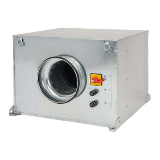
4. BESCHRIJVING 4.1. PLAATS VAN ONDERDELEN Drukslangnippels AAN/UIT- Plaats interne printplaat en drukslangnippels schakelaar Interne printplaat BELANGRIJK: In de ruimte waar de interne printplaat zit, bevinden zich drie slangetjes die gemarkeerd zijn met “V”, “P-” en “P+” en die vanuit de binnenzijde van de boxventilator steken. Als de ventilator geleverd wordt voor constante druk (COP) wordt buis “P” aangesloten. -
Page 102: Bedradingsschema En Interne Printplaat
4.2. BEDRADINGSSCHEMA EN INTERNE PRINTPLAAT Ingangsaansluitingen Beschrijving L, N, GND (J1) Voeding. 220-230 V AC 50 Hz Drukslangaansluiting 1 Aansluitnippel voor drukslang, afhankelijk van bedrijfsmodus Drukslangaansluiting 2 Stekker (J4) Ingang voor aansluiting programmatimer RTC ECOWATT (accessoire) 0V, IN, +24V (J5) Analoge ingang IN1 4-20 mA of 0-10V 0V, IN, +24V (J6) Analoge ingang IN2 4-20 mA of 0-10V... -
Page 103: Bediening Zonder Prosys Ecowatt-Console
5. BEDIENING ZONDER PROSYS ECOWATT-CONSOLE De akoestische geïsoleerde boxventilator CAB ECOWATT PLUS is voorbereid voor bedrijf onder constante druk (COP/PI DRUK) door middel van afl ezing van het drukverschil tussen de aanzuigzijde en een vooraf, in de fabriek ingestelde drukwaarde. -
Page 104: Beschrijving
6.1. BESCHRIJVING Met de PROSYS ECOWATT kunnen de instellingen gevisualiseerd en gewijzigd worden. Met deze console kunnen de volgende functies uitgevoerd worden. • Parameters en variabelen weergeven • Instellingen opslaan • Instellingen weergeven • Het apparaat en de bedrijfsmodi confi gureren •... -
Page 105: Installatie
6.3. INSTALLATIE Het is mogelijk om een enkele PROSYS ECOWATT aan één CAB ECOWATT PLUS te koppelen, of door middel van een Mod- bus-communicatienetwerk meerdere units aan één PROSYS ECOWATT-console te koppelen. Bedradingsschema individuele bediening Bedradingsschema meervoudige bediening Het is mogelijk om tot 32 boxventilatoren te koppelen aan een communicatienetwerk, om op die manier via één PROSYS ECO- WATT-console alle ventilatoren aan te sturen. - Page 106 Voer de volgende stappen uit om het kanaaladres van een ventilator te wijzigen: • Controleer dat de schakelaar AAN/UIT op “0” staat • Ga naar de interne printplaat en zet de microschakelaar SW2-2 op “AAN” (ON) • Sluit de PROSYS ECOWATT-console aan op de printplaat met de aansluiting J9 •...
- Page 107 MAX-OUTPUT Druk op “OK” < 100% SETUP LEVEL 2? Druk op “NO” < PROGRAM C:1? Druk op “YES” om veranderingen te beves gen < Program Druk op willekeurige knop om naar het hoofdscherm te gaan. <Press any key • Schakel het apparat uit ON/OFF door schakelaar in “0”. •...
-
Page 108: Algemene Parameters
6.4. ALGEMENE PARAMETERS Zet het apparaat aan met de AAN/UIT-schakelaar zodra alle kabels aangesloten zijn. Bij het inschakelen van het apparaat verschijnt het volgende scherm: L L anguage: Langue: Sprache: Idioma: E E NGLISH H CASTELLANO FRANCAISE DEUTSCH Nadat u de taal heeft ingesteld verschijnt een scherm met de volgende informatie: S S i:xxxPa a S S c:100Pa a Si: xxx... -
Page 109: Configuratie Unit Via Console
6.6. CONFIGURATIE UNIT VIA CONSOLE 6.6.1. Wijzig het instelpunt Te volgen stappen om het instelpunt vanaf het hoofdscherm te wijzigen: Si: xxx Gemeten waarde (eenheid afhankelijk van bedrijfsmodus) Sc: xxx Setpunt Ventilatorsnelheid in % (van de maximale snelheid) C: 1 Ventilatornummer, indien aangesloten op netwerk 6.6.1. -
Page 110: Bediening Pi_Druk/Cop-Modus
Pressing on “YES”, it is reloaded factory settings FACTORY SETTING? Als u “YES” kiest worden de fabrieksinstellingen hersteld MODE MODE MODE MODE PI VOLUME PROPORT. MIN-MAX <PI PRESSURE OK MODE MODE PIPRESS+RTC PIVOLUME+RTC MODE MODE MIN-MAX+RTC PROP.+RTC Werking: de getoonde parameters zijn afhankelijk van de ingestelde bedrijfsmodus. De bedrijfsmodi die eindigen op “RTC” werken uitsluitend in combinatie met de optionele programmatimer RTC. - Page 111 Access to advanced configuration parameters SETUP LEVEL 2? Toegang tot geavanceerde confi gura eparameters < Enter the password ENTER PASSWORD: Voer wachtwoord in Standaard: 1 1 1 Default: 1 1 1 It is possible to assign a new password to your device Het is mogelijk een nieuw wachtwoord aan uw CHANGE PASSWORD (channel)
- Page 112 SET POINT SET POINT SET POINT <INTERNAL <IN1 0-10V OK <CONSOLE OK CONSOLE < INTERNAL OK SET POINT SET POINT <IN1 4-20mA OK <IN2 0-10V OK SET POINT <IN2 4-20mA OK Geprogrammeerd instelpunt: - INTERN: - CONSOLE: Waarde ingesteld door PROSYS ECOWATT-console. Fabrieksinstelling - IN1/IN2 0-10V: Waarde ingesteld door externe potentiometer (0-10V) - IN1/IN2 4-20mA: Waarde ingesteld door externe potentiometer (4-20mA) Druk op...
-
Page 113: Bediening Cav/Pi_Volume-Modus
DIGITAL INPUT DIGITAL INPUT < (NC) < (NO) Digitale ingang: - NC: Normaal gesloten contact. De ventilator schakelt over op nachtstand als het contact geopend wordt. - NO: Normaal open contact. De ventilator schakelt over op nachtstand als het contact ge- sloten wordt. - Page 114 Zodra de bedrijfsmodus is gewijzigd naar PI_VOLUME/CAV verschijnen de volgende parameters: Druk op om het minimale vermogen van de motor Press to manually modify the minimum MIN-OUTPUT handma g te wijzigen output parameter to the motor < Druk op om het maximale vermogen van de mo- MAX-OUTPUT Press to manually modify the minimum...
- Page 115 SENSOR SENSOR SENSOR <IN1 0-10V OK <IN1 4-20mA OK < INTERNAL SENSOR SENSOR <IN2 4-20mA OK <IN2 0-10V OK Sensor: Sensortype - INTERN: Interne drukverschilsensor - IN1 0-10V: Externe sensor met analoog signaal 0-10V (aansluiting J5) - IN1 4-20mA:Externe sensor met analoog signaal 4-20mA (aansluiting J5) - IN2 0-10V: Externe sensor met analoog signaal 0-10V (aansluiting J6) - IN2 4-20mA:Externe sensor met analoog signaal 4-20mA (aansluiting J6) RANGE...
- Page 116 Druk op indrukken om deze parameter Press to manually modify this parameter. PARAMETERS handma g te wijzigen. It is advised not to modify. < Kp=100 Liever niet wijzigen. Druk op indrukken om deze parameter Press to manually modify this parameter. PARAMETERS handma g te wijzigen.
-
Page 117: Bediening Proportioneel/Vav-Modus
Druk op een willekeurige toets om terug te keren naar het hoofdscherm Press any key to return to main screen Program OK > <Pulsar tecla 6.6.5. Bediening PROPORTIONEEL/VAV-modus In deze stand kan de boxventilator werken met één of twee analoge ingangssignalen (4-20mA of 0-10V). De boxventilator werkt volgens de parameter met de grootste vraag. - Page 118 Druk op om het middelste gebruiksbereik IN1 SET Press to modify manually the middle range (range) handma g te wijzigen of use. < 50%HR Druk op om de breedte van het verstelbereik van IN1 (+/-) Press to modify manually the width value de sensor handma g te wijzigen of the adjustment range of the sensor <...
- Page 119 MOTOR TYPE Niet wijzigen No modify < Druk op om deze parameter handma g te wijzigen. Press to modify manually this parameter. S1-ALARM Met deze waarde kunt u een alarmbericht versturen als de waarde This value allows you to send an alarm message when die gemeten wordt door sensor IN1 een bepaald percentage van het <...
-
Page 120: Bedrijfsmodus Min/Max
6.6.6. Bedrijfsmodus MIN/MAX In deze stand werkt het bedieningskastje met het contacttype normaal open (NO) of normaal gesloten (NC). Deze bevindt zich bij de digitale ingang J11. Als de status van deze ingang gewijzigd wordt, schakelt de ventilator over naar een lagere snelheid, een bepaald percentage van de maximale snelheid. -
Page 121: Bediening Met Optionele Programmatimer Rtc Ecowatt En Prosys Ecowatt-Console (Accessoires)
Het is mogelijk een nieuw wachtwoord aan uw apparaat It is possible to assign a new password to your device CHANGE PASSWORD toe te wijzen (kanaal) (channel) MOTOR TYPE Niet wijzigen No modify < DIGITAL INPUT DIGITAL INPUT < (NO) <... -
Page 122: Installatie
7.1. INSTALLATIE Zoals in onderstaande afbeelding wordt getoond is dit accessoire een elektroni- sche component die in de boxventilator geïnstalleerd moet worden. PROGRAMMEERTIMER RTC ECOWATT Voer de volgende stappen uit om dit correct uit te voeren: 1. Schakel de stroomvoorziening uit met de AAN/UIT-schakelaar aan de voorzijde. 2. -
Page 123: Programmeren
7.2. PROGRAMMEREN BELANGRIJK: Voordat u begint met de programmering is het belangrijk de desbetreffende bedrijfsmodus te kiezen. Zie punt 6.6.1. Bedrijfsmodus wijzigen van deze handleiding, en kies één van deze modi: PI DRUK, PI VOLUME+RTC, PROPORTIO- NEEL+RTC of MIN-MAX+RTC. Tijdens het programmeren moeten de volgende parameters gedefi nieerd worden: •... - Page 124 Op YES drukken, terug naar hoofdscherm Pressing on , back to main screen EXIT? Op CONT drukken, verder programmeren Pressing on CONT , continue programming CONT CONT CONT MONDAY Start time for period frame T1 on Monday Star jd voor de periode T1 op maandag 09:00 MONDAY Start time for period frame T2 on Monday...
- Page 125 Instelpunt in % jdens jdsperiode in verhouding tot SET T1 Set point in % during period frame over operation mode eerder geselecteerde bedrijfmodus (UIT, 0-100%) previously selected (OFF, 0-100%) Verder met procedure Forward sequence DATE START Begindatum vakan eperiode Starting date holidays period 19/12/14 HOUR START Begin jd vakan eperiode...
-
Page 126: Samenvatting Tabel Instelwaarden
7.3. SAMENVATTING TABEL INSTELWAARDEN Register Min. Max. Beschrijving 23:59 Starttijd programma Period T1 Period T2 0min 480min Tijdsduur programma Period T3 Set T1 Set T2 100% Percentage in verhouding tot instelpunt Set T3 Startdatum 00:00 23:59 Startdatum vakantieperiode Begintijdstip 00:00 23:59 Starttijdstip vakantieperiode Einddatum... -
Page 127: Geheugenkaart Modbus
8.2. GEHEUGENKAART MODBUS Holding registers Reg.nr. Register Min. Max. Beschrijving Standaardinstelling Opmerkingen 0=AC (wisselstroom) TipoMotor Motortype 1=DC (gelijkstroom) 0=PI_Druk 1=PI_Volume 2=Proportioneel 3=Max-Min ModoFun Bedrijfsmodus 4=PI_Druk+RTC 5=PI_Volume+RTC 6=Proportioneel+RTC 7=Max-Min+RTC 0=Intern 1=IN1 0-10V Sensortype in PI_DRUK of SensorPI 2=IN1 4-20mA PI_VOLUME-modus 3=IN2 0-10V 4=IN2 4-20mA 0=GEEN 1=0-10V %HR... - Page 128 Reg.nr. Register Min. Max. Beschrijving Standaardinstelling Opmerkingen S2Alarm Stappen van 5% Alarm analoge ingang 2 MinRPM Stappen van 100 Min RPM alarm Minimumspanning wissel- VacMIN Stappen van 10 stroommotor Stappen van %HR Achtergrondschaal in IN1 Range Stappen van °C proportionele modus 2000 Stappen van PPM ingang 1...
- Page 129 Reg.nr. Register Min. Max. Beschrijving Standaardinstelling Opmerkingen VIERNES T2 0x0000 0x063b Uren/minuten 0x0300 Start periode 2 vrijdag VIERNES T3 0x0000 0x063b Uren/minuten 0x0480 Start periode 3 vrijdag SABADO T1 0x0000 0x063b Uren/minuten 0x0200 Start periode 1 zaterdag SABADO T2 0x0000 0x063b Uren/minuten 0x0300...
-
Page 130: Onderhoud
9. ONDERHOUD Voordat u de boxventilator opent, moet u zeker weten dat deze is losgekoppeld van de netspanning, nadat u deze eerst heeft uitgeschakeld. Voorkom dat iemand anders de boxventilator kan aansluiten terwijl hieraan gewerkt wordt. De ventilatoren moeten regelmatig geïnspecteerd worden. Deze inspecties moeten uitgevoerd worden met inachtneming van de bedrijfsomstandigheden van de machine, zodat er geen vuil en stof op de ventilatorschoepen, waaier, motor of rooster op- hoopt. - Page 132 S&P SISTEMAS DE VENTILACIÓN, S.L.U. C. Llevant, 4 Polígono Industrial Llevant 08150 Parets del Vallès Barcelona - España Tel. +34 93 571 93 00 www.solerpalau.com Ref. 9023052700-03...
Need help?
Do you have a question about the CAB ECOWATT PLUS and is the answer not in the manual?
Questions and answers