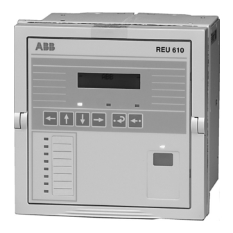
ABB REU 610 Operator's Manual
Voltage relay
Hide thumbs
Also See for REU 610:
- Technical reference manual (141 pages) ,
- Installation manual (40 pages) ,
- Operator's manual (65 pages)
Table of Contents
Advertisement
Quick Links
Advertisement
Table of Contents

Related Manuals for ABB REU 610


Summary of Contents for ABB REU 610
- Page 1 Voltage Relay REU 610 Operator's Manual - ANSI Version...
-
Page 3: Table Of Contents
1MRS755971 Voltage Relay REU 610 Issued: 31.01.2006 Operator's Manual - ANSI Version Version: A/01.02.2006 Contents 1. Introduction................. 7 1.1. This manual................7 1.2. Use of symbols..............7 1.3. Intended audience..............7 1.4. Product documentation............8 1.5. - Page 4 REU 610 Voltage Relay 1MRS755971 Operator's Manual - ANSI Version 4.2.2.4. How to acknowledge and reset targets, output contacts and memorized values........36 4.3. Protection relay targets............37 4.3.1. Target LEDs............37 4.3.1.1. Green target LED........37 4.3.1.2.
- Page 5 Copyrights The information in this document is subject to change without notice and should not be construed as a commitment by ABB Oy. ABB Oy assumes no responsibility for any errors that may appear in this document. In no event shall ABB Oy be liable for direct, indirect, special, incidental or...
-
Page 7: Introduction
Introduction 1.1. This manual This manual provides basic information on the voltage relay REU 610 and presents detailed instructions on how to use the human-machine interface (HMI) of the relay. In addition to the instructive part, a short chapter on commissioning and maintenance of the relay is included. -
Page 8: Product Documentation
1MRS755971 Operator's Manual - ANSI Version 1.4. Product documentation In addition to the relay and this manual, the delivery contains the following relay-specific documentation: Table 1.4.-1 REU 610 product documentation Name Document ID Certificate of verification 1MRS081662 Installation Manual 1MRS752265-MUM... -
Page 9: Safety Information
1MRS755971 Voltage Relay REU 610 Operator's Manual - ANSI Version Safety information Dangerous voltages can occur on the connectors, even though the auxiliary voltage has been disconnected. Non-observance can result in death, personal injury or substantial property damage. Only a competent electrician is allowed to carry out the electrical installation. -
Page 11: Product Overview
Product overview 3.1. Use of the relay The voltage relay REU 610 is a versatile multifunction protection relay mainly designed for overvoltage and undervoltage protection and for supervision of medium voltage distribution networks. The relay can also be used for protecting generators, motors and transformers. - Page 12 REU 610 Voltage Relay 1MRS755971 Operator's Manual - ANSI Version Three normally open trip contacts Two change-over (form c) non-trip contacts and three additional change- over (form c) non-trip contacts on the optional I/O module Output contact functions freely configurable for wanted operation...
-
Page 13: Operation
1MRS755971 Voltage Relay REU 610 Operator's Manual - ANSI Version Operation 4.1. HMI features 4.1.1. Front panel The front panel of the relay contains: Alphanumeric 2 × 16 characters’ LCD with backlight and automatic contrast control Three target LEDs (green, yellow, red) with fixed functionality... -
Page 14: Display
Display test at power up, display inverted 4.1.2.2. Display modes When the display is in the idle mode, the name of the feeder is displayed, which by default is - ABB -. To change the name of the feeder, use SPA parameter M20. A040217 Fig. 4.1.2.2.-1 Display in the idle mode When the display is in the view mode, you can only view the settings. -
Page 15: Display Backlight
1MRS755971 Voltage Relay REU 610 Operator's Manual - ANSI Version SETTINGS *GRP1 :1.2 1 A051575 Fig. 4.1.2.2.-3 Display in the setting mode 4.1.2.3. Display backlight Normally the backlight of the display is off. Turn the backlight on by pressing an arrow button on the HMI. If the HMI panel is not used for approximately five minutes, the backlight is turned off automatically. -
Page 16: Main Menu
REU 610 Voltage Relay 1MRS755971 Operator's Manual - ANSI Version Increase or decrease the activated digit, shift the activated decimal point, or navigate between options by using Cancel and return the display to the previous mode (view mode or idle mode), by pressing Table 4.1.3.-1... -
Page 17: Submenu
1MRS755971 Voltage Relay REU 610 Operator's Manual - ANSI Version 4.1.5. Submenu The menu structure contains several subgroups. The name of the main menu group is always shown on the first line. The second line displays either the name of the group menu, the name of the parameter and the parameter value, or just the parameter value, in which case it is also the name of the parameter. -
Page 18: Spa Password
REU 610 Voltage Relay 1MRS755971 Operator's Manual - ANSI Version 6. To store the new password and return the display to the view mode, press . The display confirms the storage by flashing “- - -” once on the display. -
Page 19: How To Select Language
1MRS755971 Voltage Relay REU 610 Operator's Manual - ANSI Version 6. To store the new SPA password and return the display to the view mode, . The display confirms the storage by flashing "- - -" once on press the display. -
Page 20: How To Set The Real-Time Clock
REU 610 Voltage Relay 1MRS755971 Operator's Manual - ANSI Version Parameter Menu Main Menu Group Menu MEASUREMENTS RECORDED DATA OPERATION SETTINGS CONFIGURATION CONFIGURATION FUNCTION TEST/DI COMMUNICATION CONFIGURATION LANGUAGE ENGLISH INFO Confirm ESPANOL MEMORY SETTINGS PORTUGESE FREQUENCY Cancel U NOMINAL PASSWORD HMI... -
Page 21: How To Reset The Trip Lockout Function
1MRS755971 Voltage Relay REU 610 Operator's Manual - ANSI Version Parameter Menu Main Menu Group Menu MEASUREMENTS RECORDED DATA OPERATION SETTINGS CONFIGURATION CONFIGURATION FUNCTION TEST/DI COMMUNICATION LANGUAGE INFO MEMORY SETTINGS FREQUENCY U NOMINAL PASSWORD HMI CONFIGURATION Confirm YY-MM-DD (00-23) TIME hh.mm;ss... -
Page 22: How To Switch Between Front And Rear Connection
REU 610 Voltage Relay 1MRS755971 Operator's Manual - ANSI Version Main Menu Group Menu Parameter Menu MEASUREMENTS RECORDED DATA OPERATION OPERATION OPERATION LOCKOUT RESET TRIP LOCKOUT Confirm SETTINGS Cancel CONFIGURATION INFO A040239 Fig. 4.1.10.-1 Resetting trip lockout function 4.1.11. How to switch between front and rear connection... -
Page 23: Target Led For Front Communication
1MRS755971 Voltage Relay REU 610 Operator's Manual - ANSI Version When the front connection has been selected and there is no communication for approximately five minutes, the rear connection is automatically activated. To keep the front connection continuously active, press simultaneously when connecting the auxiliary voltage to the relay. -
Page 24: Hmi Operation Levels
REU 610 Voltage Relay 1MRS755971 Operator's Manual - ANSI Version Select the rear communication protocol as follows: 1. Press an arrow button to access the main menu. 2. Use the arrow buttons to select CONFIGURATION\COMMUNICATION \REAR PROTOCOL and press . The cursor is at the setting currently in use (for example SPA). -
Page 25: How To Monitor Measured Values
1MRS755971 Voltage Relay REU 610 Operator's Manual - ANSI Version Stored event values from the protection functions Registered number of pickups of protection functions Continuously updated registers of actual values from protection functions OPERATION Resetting of trip lockout INFO Information on the relay, such as device type and relay serial number 4.2.1.2. - Page 26 REU 610 Voltage Relay 1MRS755971 Operator's Manual - ANSI Version Parameter Menu Main Menu Group Menu MEASUREMENTS MEASUREMENTS MEASUREMENTS VT:0.00 VTx 0.00 VT:0.00 VTx 0.00 VT:0.00 VTx 0.00 RECORDED DATA VT:0.00 VT%0.0 VTx 0.00 VTx 0.00 OPERATION MEASUREMENTS MEASUREMENTS DEMAND VALUES 1 minute VT:0.00...
-
Page 27: How To Monitor Recorded Data
1MRS755971 Voltage Relay REU 610 Operator's Manual - ANSI Version 4.2.1.3. How to monitor recorded data The contents of the event register and the information on number of pickups and trips are found under the main menu group RECORDED DATA. -
Page 28: Info Menu Group
REU 610 Voltage Relay 1MRS755971 Operator's Manual - ANSI Version 4.2.1.4. INFO menu group The main menu group INFO contains information which you may need when ordering repair service. 1. Press an arrow button to access the main menu. 2. Use the arrow buttons to select INFO and press to enter the first submenu. -
Page 29: Technical Level
1MRS755971 Voltage Relay REU 610 Operator's Manual - ANSI Version Main Menu Parameter Menus MEASUREMENTS RECORDED DATA OPERATION SETTINGS CONFIGURATION INFO INFO REU 610 xxxxxxxx Cancel YYYYMMDD INFO INFO 1MRSxxxxxx x CPU MODULE xxxxxxxx COM. MODULE INFO INFO 1MRSxxxxxx x... -
Page 30: How To Change Settings
REU 610 Voltage Relay 1MRS755971 Operator's Manual - ANSI Version The views are used for reading and setting parameters, which are divided into two main groups: SETTINGS CONFIGURATION 4.2.2.2. How to change settings The actual settings consist of the settings of group 1 or group 2, depending on which group has been selected to be active (indicated by an asterisk "*"). - Page 31 1MRS755971 Voltage Relay REU 610 Operator's Manual - ANSI Version 6. The first digit of the setting value of the parameter to be edited starts to flash. Use to move the cursor and to increase or decrease the number. 7. To store a new value and return the display to the view mode, press .
- Page 32 REU 610 Voltage Relay 1MRS755971 Operator's Manual - ANSI Version Parameter Menus Group Menu Main Menu MEASUREMENTS RECORDED DATA OPERATION SETTINGS SETTINGS Edit/Confirm SETTINGS SETTINGS * GRP 1 :0.00 PROTEC. ELEMENTS 59P-1 VTx0.00 GRP 2 :0.00 59P-1 TDLY:0.00 Cancel 59P-1...
- Page 33 1MRS755971 Voltage Relay REU 610 Operator's Manual - ANSI Version SGB1...SGB5 Digital inputs (DI1...DI5) SGR1...SGR8 Output contacts (PO1, PO2, PO3, SO1, SO2, SO3, SO4, SO5) SGL1...SGL8 Programmable LEDs To set functions via switchgroups: 1. Press an arrow button to access the main menu.
-
Page 34: Configuration
REU 610 Voltage Relay 1MRS755971 Operator's Manual - ANSI Version Parameter Menu SETTINGS SETTINGS * GRP 1 :xxx * GRP 1 :x x Confirm GRP 2 :xxx Cancel Set the bit state (0 or 1) Scroll for the desired bit A040259 Fig. - Page 35 1MRS755971 Voltage Relay REU 610 Operator's Manual - ANSI Version Main Menu Group Menu Parameter Menus MEASUREMENTS RECORDED DATA OPERATION SETTINGS CONFIGURATION CONFIGURATION CONFIGURATION CONFIGURATION DI1 STATUS FUNCTION TEST/DI FUNC.TEST COMMUNICATION DI STATUS DI2 STATUS LED TEST DI3 STATUS LANGUAGE...
-
Page 36: How To Acknowledge And Reset Targets, Output Contacts And Memorized Values
REU 610 Voltage Relay 1MRS755971 Operator's Manual - ANSI Version Main Menu Group Menu Parameter Menus MEASUREMENTS RECORDED DATA OPERATION SETTINGS CONFIGURATION CONFIGURATION FUNCTION TEST/DI COMMUNICATION LANGUAGE INFO MEMORY SETTINGS CONFIGURATION FREQUENCY FREQUENCY U NOMINAL FREQUENCY PASSWORD HMI TIME CONFIGURATION... -
Page 37: Protection Relay Targets
1MRS755971 Voltage Relay REU 610 Operator's Manual - ANSI Version 4.3. Protection relay targets The operation of the relay can be monitored by means of three different HMI targets: Three target LEDs with fixed functionality: Ready Pickup/Alarm Trip Eight programmable target LEDs Text message on the display The protection functions are not affected by fault targets. -
Page 38: Yellow Target Led
REU 610 Voltage Relay 1MRS755971 Operator's Manual - ANSI Version 4.3.1.2. Yellow target LED A040266 Fig. 4.3.1.2.-1 Yellow target LED Target off: No protection stage has picked up. Lit target: A protection element has picked up or generated an alarm. The pickup and alarm target can be selected to be either latching or non-latching with the SGF switches. -
Page 39: Programmable Target Leds
1MRS755971 Voltage Relay REU 610 Operator's Manual - ANSI Version 4.3.1.4. Programmable target LEDs In addition to the three fixed LEDs, the relay contains eight LEDs which you can program to target the status of different type of relay signals. The... -
Page 40: Disturbance Recorder Target
REU 610 Voltage Relay 1MRS755971 Operator's Manual - ANSI Version TRIP 59P-2 Uab/bc A051582 Fig. 4.3.2.1.-2 Trip target Latching and non-latching targets A latching operation target message remains on the display until manually cleared or until replaced by a message of higher priority. However, if the fault is stable and has not disappeared, the operation target message and the LED (s) are not cleared. -
Page 41: Self-Supervision
1MRS755971 Voltage Relay REU 610 Operator's Manual - ANSI Version 4.3.2.3. Self-supervision There are two types of fault targets; internal relay fault (IRF) targets and warnings. Internal relay faults prevent relay operation. Warnings are less severe faults and continued relay operation with full or reduced functionality is allowed. - Page 42 REU 610 Voltage Relay 1MRS755971 Operator's Manual - ANSI Version Table 4.3.2.3.-1 IRF codes (Continued) Fault code Type of fault Error in optional output relay SO4 Error in optional output relay SO5 Error in the enable signal for optional output relay SO3, SO4 or...
- Page 43 1MRS755971 Voltage Relay REU 610 Operator's Manual - ANSI Version If more than one type of fault occur at the same time, one single numeric code which targets all the faults is displayed. For instance, the code33 implies two faults: the battery is low and the DNP 3.0 module is faulty. The fault code is composed of the weighting factors assigned to each fault type as follows: 1 + 32;...
-
Page 44: Detachable Plug-In Unit
REU 610 Voltage Relay 1MRS755971 Operator's Manual - ANSI Version Table 4.3.2.3.-2 Warning codes (Continued) Fault Weight Description value DNP 3.0 configuration DNP 3.0 configuration error error DNP 3.0 parameters should be formatted and re-configured DNP 3.0 module faulty Faulty memory in DNP 3.0 card or communication lost between DNP 3.0 card... -
Page 45: Detaching And Installing The Plug-In Unit
1MRS755971 Voltage Relay REU 610 Operator's Manual - ANSI Version 4.4.2. Detaching and installing the plug-in unit Before detaching the plug-in unit from the case, the auxiliary voltage must be disconnected. To detach the plug-in unit: 1. Lift the lower handle until the spring-loaded locks on both sides of the handle are released and the unit is pushed about 6 mm out of the case. -
Page 46: Inserting And Changing The Battery
REU 610 Voltage Relay 1MRS755971 Operator's Manual - ANSI Version However, it is highly recommended that all characters in the order number of the substitute plug-in unit, except for those indicating a spare part, should match the ones of the case. Otherwise, it may result in loss of significant functionality in the application. - Page 47 1MRS755971 Voltage Relay REU 610 Operator's Manual - ANSI Version 1. Gently remove the battery with, for example, a flat-ended screwdriver. Be careful not to drop the battery inside the plug-in unit. 2. Insert a new battery under the battery holder and ensure that you install the battery with the correct polarity to avoid damage to the equipment.
-
Page 49: Commissioning And Maintenance
1MRS755971 Voltage Relay REU 610 Operator's Manual - ANSI Version Commissioning and maintenance The relay should be subject to regular tests and maintenance in accordance with national regulations and instructions. Prior to commissioning, the functionality of the application-specific relay configuration and settings have to be tested. -
Page 50: Commissioning Instructions
REU 610 Voltage Relay 1MRS755971 Operator's Manual - ANSI Version 5.1. Commissioning instructions Relay commissioning is carried out to confirm correct operation of the relay when it is taken into use. Polarity checking of voltage transformers should be performed to confirm that the wiring circuitry between the voltage transformers and the relay is correct, which is a prerequisite for the protection functions in the relay to operate correctly. -
Page 51: Relay Verification
1MRS755971 Voltage Relay REU 610 Operator's Manual - ANSI Version When the plug-in unit is removed from the case, internals of the case must not be touched. Relay case internals may have high voltage potential and touching these may cause personal injury. -
Page 52: Function Test
REU 610 Voltage Relay 1MRS755971 Operator's Manual - ANSI Version applied voltage × Value on LCD (VT)= energizing input rated vol l tage 5.4. Function test This section describes how the signal routing from protection functions to, and operation of, the output contacts in the relay can be tested. -
Page 53: Digital Input Test
1MRS755971 Voltage Relay REU 610 Operator's Manual - ANSI Version Table 5.4.-1 Function test (Continued) Number Function Pickup of element 59N-2 Trip of element 59N-2 External trip It is also possible to test the output contacts via serial communication by using the O parameters. -
Page 54: Testing Overvoltage Protection
REU 610 Voltage Relay 1MRS755971 Operator's Manual - ANSI Version The test is performed as a secondary test, by applying voltage to the voltage energizing inputs. To enable secondary testing without accidentally blocking other relays or tripping circuit breakers in the system, the relay has to be disconnected. -
Page 55: Spare Parts
1MRS755971 Voltage Relay REU 610 Operator's Manual - ANSI Version Spare parts 6.1. Plug-in unit The relay’s construction allows a spare part in form of a plug-in unit. The outage time can therefore be reduced to a minimum in case the relay should fail. -
Page 57: Repair
Contact the manufacturer or the nearest representative for further information on checking, service and re-calibration of the relay. When contacting ABB for ordering repair services, give a description of the fault and state the fault code, if applicable. -
Page 59: Ordering Information
1MRS755971 Voltage Relay REU 610 Operator's Manual - ANSI Version Ordering information For ordering information, refer to the Technical Reference Manual. -
Page 61: Abbreviations
1MRS755971 Voltage Relay REU 610 Operator's Manual - ANSI Version Abbreviations Abbreviation Description ASCII American Standard Code for Information Interchange Central processing unit Digital input Human-machine interface IDMT Inverse definite minimum time characteristic Internal relay fault Liquid crystal display Light-emitting diode... - Page 64 ABB Oy Distribution Automation P.O. Box 699 FI-65101 VAASA FINLAND Tel. +358 10 22 11 Fax. +358 10 224 1094 www.abb.com/substationautomation...
Need help?
Do you have a question about the REU 610 and is the answer not in the manual?
Questions and answers