BIRD TERMALINE 8920 Series Manual
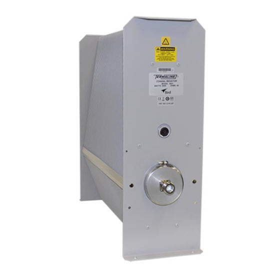
Load resistor
Hide thumbs
Also See for TERMALINE 8920 Series:
- Operation manual (33 pages) ,
- Instruction book (30 pages) ,
- Operation manual (32 pages)
Table of Contents
Advertisement
Quick Links
Advertisement
Table of Contents

Subscribe to Our Youtube Channel
Related Manuals for BIRD TERMALINE 8920 Series


Summary of Contents for BIRD TERMALINE 8920 Series
- Page 1 ® TERMALINE LOAD RESISTOR SERIES 8920 MODELS: 8921 8922 8926 8927 8928 8922D 8926D 8927D ©Copyright 2008 by Bird Electronic Corporation Instruction Book Part Number 920-8920S Rev. H Termaline® and Thruline® are Registered Trademarks of Bird Electronic Corporation...
- Page 2 I am not blank...
-
Page 3: Safety Precautions
Safety Precautions The following are general safety precautions that are not necessarily related to any specific part or procedure, and do not necessarily appear elsewhere in this publication. These precau- tions must be thoroughly understood and apply to all phases of operation and maintenance. WARNING Keep Away From Live Circuits Operating Personnel must at all times observe general safety precautions. -
Page 4: Warning Statements
This symbol indicates that a shock hazard exists if the precautions in the instruction manual are not follwed. The caution symbol appears on the equipment indicating there is impor- tant information in the instruction manual regarding that particular area. This symbol indicates that the unit radiates heat and should not be touched while hot. -
Page 5: Safety Statements
Safety Statements USAGE ANY USE OF THIS INSTRUMENT IN A MANNER NOT SPECIFIED BY THE MANUFACTURER MAY IMPAIR THE INSTRUMENT’S SAFETY PROTECTION. EL USO DE ESTE INSTRUMENTO DE MANERA NO ESPECIFICADA POR EL FABRICANTE, PUEDE ANULAR LA PROTECCIÓN DE SEGURIDAD DEL INSTRUMENTO. - Page 6 SERVICE SERVICING INSTRUCTIONS ARE FOR USE BY SERVICE - TRAINED PERSONNEL ONLY. TO AVOID DANGEROUS ELECTRIC SHOCK, DO NOT PERFORM ANY SERVICING UNLESS QUALIFIED TO DO SO. SERVICIO LAS INSTRUCCIONES DE SERVICIO SON PARA USO EXCLUSIVO DEL PERSONAL DE SERVICIO CAPACITADO. PARA EVITAR EL PELIGRO DE DESCARGAS ELÉCTRICAS, NO REALICE NINGÚN SERVICIO A MENOS QUE ESTÉ...
- Page 7 CONNECT INTERLOCK TO TRANSMITTER/GENERATOR/AMPLIFIER BEFORE OPERATING. BRANCHER LE VERROUILLAGE À L’ÉMETTEUR/GÉNÉRATEUR/ AMPLIFICATEUR AVANT EMPLOI. CONECTE EL INTERBLOQUEO AL TRANSMISOR/GENERADOR/ AMPLIFICADOR ANTES DE LA OPERACION. VOR INBETRIEBNAHME VERRIEGELUNG AM SENDER/GENERATOR/ VERSTÄRKER ANSCHLIESSEN. PRIMA DI METTERE IN FUNZIONE L’APPARECCHIO, COLLEGARE IL DISPOSITIVO DI BLOCCO AL TRASMETTITORE/GENERATORE/ AMPLIFICATORE.
-
Page 8: About This Manual
About This Manual This manual covers the operating and maintenance instructions for the following models: 8921 8922 8926 8927 8928 8922D 8926D 8927D Changes to this Manual We have made every effort to ensure this manual is accurate. If you discover any errors, or if you have suggestions for improving this manual, please send your comments to our Solon, Ohio factory. -
Page 10: Table Of Contents
Table of Contents Safety Precautions ............i Safety Symbols . -
Page 11: Chapter 1 Introduction
Bird 8920 Series Loads are portable, 50 ohm, coaxial RF transmission line terminations, designed for frequency ranges of DC – 1 GHz. Bird 8920D Series Loads are identical, except that they are designed for the UHF (470 – 860 MHz) band. They provide accurate, dependable, and low reflection line terminations. Up to 5000 watts of RF power can be dissipated. -
Page 13: Chapter 2 Theory Of Operation
Theory of Operation Load Resistor Bird 8920 series loads consist of a thin-film-on-ceramic resistor immersed in a dielectric coolant. The resistor, indi- vidually selected for its accuracy, is enclosed in a special housing. When surrounded by the coolant, this produces a uniform, practically reflectionless line termination over the specified frequencies. -
Page 15: Chapter 3 Installation
If the shipping container is not damaged, unpack the unit. Save shipping materi- als for repackaging. 3. Inspect unit for visual signs of damage. Note: If there is damage, immediately notify the shipping carrier and Bird Elec- tronic Corporation. Mounting Place the load in a dry, dust and vibration free environment. -
Page 16: Setup
2. Install the vent plug. Refer to Figure 2 and Figure 3. Installing Thermoswitch Bird 8920 series loads can be equipped with an optional interlock thermoswitch, P/N 8890-008. It is normally closed, opening at 236 °C (457 °F), with a rating of 10A @ 120 VAC and 5A @ 230 VAC. -
Page 17: Connecting Rf Power
Figure 4 Thermoswitch Assembly Connecting RF Power After installing the load, the RF transmission line can be attached using standard coaxial line coupling kits. WARNING Never attempt to connect or disconnect RF equipment from the transmission line while RF power is being applied. -
Page 18: Unflanged Coupling
Unflanged Coupling Note: To couple the unflanged connector with an unflanged RF line, use an appropriate coupling kit. Refer to Figure 6 while following the instructions below: 1. Insert the center bullet and bottom it on the midpoint nibs. 2. Position the outer sleeve, with clamping bands, over the input connector. 3. -
Page 19: Chapter 4 Operating Instructions
Normal Operation Bird 8920 series loads have no indicators or operating controls. They require no special operating procedures or surveil- lance when their performance limits are not exceeded. Follow the instructions for the specific transmitter equipment. -
Page 21: Chapter 5 Maintenance
Chapter 5 Maintenance This chapter covers cleaning, inspection, trouble-shooting, and specifications for the Bird 8920 series loads. WARNING Never attempt to connect or disconnect RF equipment from the transmission line while RF power is being applied. Leaking RF energy is a potential health hazard. -
Page 22: Maintenance
Maintenance Cleaning The outside surface of the instrument should be wiped free of dust and dirt when necessary. Excessive dust on the cooling fins will interfere with heat dissipation. Clean the RF connector, both metallic and insulating surfaces, with a dry, non-residue forming solvent. -
Page 23: Coolant Level
RF Connector The Model 8921, only, has a special Bird “QC” connector which allows easy changing of the RF connector. This does not disturb the coolant seal or affect the electrical continuity of the load. To change the connector, proceed as follows: 1. -
Page 24: Load Resistor
Load Resistor WARNING Oil is slippery. If a leak occurs, be careful not to fall. 1. Remove the vent plug. 2. Install the shipping plug. 3. Stand the unit on its back with the connector end up. Note: Support the unit to prevent damage to the interlock Note: In this position there is no danger of the coolant pouring out through the resistor hole. -
Page 25: Customer Service
Any maintenance or service procedure beyond the scope of those in this chapter should be referred to a qualified service center. If you need to return the unit for any reason, request an RMA through the Bird Technologies website (link shown below). All instruments returned must be shipped prepaid and to the attention of the RMA number. -
Page 26: Specifications
Specifications Frequency Range 8921-MM-3-150 100 - 200 MHz 8922D, 8926D, 8927D 470 – 860 MHz All other models DC – 1 GHz Power Rating 5000 W continuous duty Peak Power for Pulse Width 1 µs 150 kW 10 µs 115 kW 100 µs 80 kW 1000 µs... -
Page 27: Replacement Parts
Replacement Parts Description Part Number RF Load Resistor: 8921 8890A050 8922, 8922D 8892-015 8926 8891-050 8926D 8891-071 8927 8897-003 8927D 8897-006 8928 8898-006 Resistor O-Ring 5-230 Clamping Band Assembly 2430-055 Plug Vent 2450-094 Shipping 2450-049 Interlock Thermoswitch 8890-008 Thermoswitch Body 8890-005 Thermoswitch Jack 2450-018... -
Page 28: Available "Qc" Type Connectors
Available “QC” Type Connectors Connector Part Number BNC-Female 4240-125 BNC-Male 4240-132 C-Female 4240-100 C-Male 4240-110 HN-Female 4240-268 HN-Male 4240-278 LC-Female 4240-031 LC-Male 4240-025 Open Term. 4240-080 # 10-32 Nut LT-Female 4240-018 LT-Male 4240-012 N-Female 4240-062 N-Male 4240-063 SC-Female 4240-090 SMA-Female 4240-336 SMA-Male 4240-334... -
Page 29: Limited Warranty
Limited Warranty All products manufactured by Seller are warranted to be free from defects in material and workmanship for a period of one year, unless otherwise specified, from date of shipment and to conform to applicable specifications, draw- ings, blueprints and/or samples. Seller’s sole obligation under these warranties shall be to issue credit, repair or replace any item or part thereof which is proved to be other than as warranted;...
Need help?
Do you have a question about the TERMALINE 8920 Series and is the answer not in the manual?
Questions and answers