Table of Contents
Advertisement
Quick Links
Instructions and Parts List
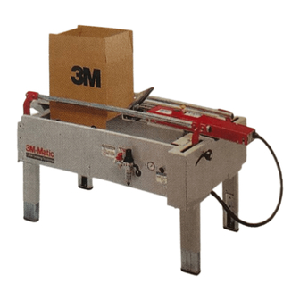
3M-Matic
300cf
Case Former
Type 29800
For Use With 3M-Matic™:
100a Type 29600, 120a Type 19700,
120a3 Type 19700, 120ab Type 19700,
200a Type 39600, 700a Type 39600,
800a Type 39600, 800a3 Type 39600,
800ab Type 39600 Case Sealers
Note: The 300cf is not compatible with the Low
Tape Sensor Kit or outboard tape roll mounting
Serial No.
For reference, record machine serial number here.
3M Packaging Systems Division
3M Center, Building 220-8W-01
St. Paul, MN 55144-1000
™
Important Safety
Information
Read "Important Safeguards",
pages 3 and 4, BEFORE
INSTALLING OR
OPERATING THIS
EQUIPMENT.
"3M-Matic" is a Trademark of 3M,
St. Paul, MN 55144-1000
Printed in U.S.A.
© 3M 1999 44-0009-1974-4(A49.0)
Advertisement
Table of Contents

Related Manuals for 3M 3M-Matic 300cf


Summary of Contents for 3M 3M-Matic 300cf
- Page 1 Note: The 300cf is not compatible with the Low Tape Sensor Kit or outboard tape roll mounting Serial No. For reference, record machine serial number here. "3M-Matic" is a Trademark of 3M, 3M Packaging Systems Division St. Paul, MN 55144-1000 3M Center, Building 220-8W-01 Printed in U.S.A.
- Page 2 Minimum billing on parts orders will be $25.00. Replacement part prices available on request. $10.00 restocking charge per invoice on returned parts. Note : Outside the U.S., contact the local 3M subsidiary for parts ordering information. "3M-Matic", "AccuGlide" and “Scotch” are trademarks 3M Packaging Systems Division of 3M, St.
- Page 3 Replacement Parts And Service Information To Our Customers: This is the 3M-Matic™/AccuGlide™/Scotch™ brand equipment you ordered. It has been set up and tested in the factory with "Scotch" brand tapes. If any problems occur when operating this equipment, and you desire a service call, or phone consultation, call, write or Fax the appropriate number listed below.
-
Page 4: Table Of Contents
Instruction Manual 300cf Case Former Type 29800 Table of Contents Page Intended Use ............................. Equipment Warranty and Limited Remedy ..................Contents ............................Important Safeguards ........................3 - 4 Specifications ..........................5 - 6 Air Power Requirements .................. Box Board ......................Box Weight and Size Capacities .............. -
Page 5: Intended Use
Intended Use The 3M-Matic 300cf Case Former has been designed and tested for use with the following 3M-Matic™ case sealers: 100a, 120a, 120a3, 120ab, 200a, 700a, 800a, 800a3 and 800ab. A regular slotted carton is placed on the center rail of the case former and the bottom side flaps are automatically closed by the machine. A pneumatic device pushes the carton into the case sealer for bottom sealing of the carton. -
Page 6: Equipment Warranty And Limited Remedy
3M is notified of the problem no later than five (5) calendar days after the warranty period. If 3M is unable to repair or replace the part within a reasonable time, then 3M, at its option, will replace the equipment or refund the purchase price. -
Page 7: Important Safeguards
Important Safeguards The "Emergency Stop" label, shown in Figure 1-2, This safety alert symbol identifies is attached to the top of the adjustable carton ejector important safety messages in this assembly around the E-Stop push-button. The label manual. READ AND UNDERSTAND THEM reminds operators and casual personnel of the BEFORE INSTALLING OR OPERATING function of this switch. - Page 8 Important Safeguards (Continued) The "Operation Mode" label, shown in Figure 1-6 is The "Safety Instructions label, shown in attached on the left side of the machine frame below Figure 1-4, is attached on the left side of the the Manual/Automatic switch. The label indicates machine frame.
-
Page 9: Specifications
Specifications Air Power Requirements 517 kPa minimum gauge pressure, 6.0 m /h @ 21°C, 101 kPa maximum at maximum cycle rate [75 PSIG minimum gauge pressure, 3.5 SCFM maximum at maximum random cycle rate]. A pressure regulator-filter is included. For best operation set pressure regulator to 90 PSIG. Box Board 125 to 275 P.S.I. -
Page 10: Machine Dimensions
Specifications (Continued) Machine Dimensions Minimum 1375 1385 [Inches] [4.81] [24.0] [27.0] [54.1] [54.6] [24.3] [30.2] Maximum 1705 1715 [Inches] [4.81] [30.5] [33.5] [67.1] [67.6] [24.3] [30.2] Casters are optional Includes the height of a plastic foot which is removed if casters are used. L1 is 300cf Case Former connected to 120a, 120a3 L2 is 300cf Case Former connected to 100a, 200a, 700a, 800a, 800a3 Add 30 mm to these dimensions when connecting to a 120ab or 800ab... -
Page 11: Installation And Set-Up
If damage is evident, file a damage minimum to 775 mm [30.5 inch] maximum. claim immediately with the transportation company and also notify your 3M Representative. Refer to Figure 2-1 and adjust the bed height as follows: Machine Set-Up (a) Block up the machine frame to allow Important –... - Page 12 Installation and Set-Up (Continued) Figure 2-2 – Mounting Bracket Installation...
- Page 13 Installation and Set-Up (Continued) 4. Pneumatic Connection The case former requires a 5.2 bar gauge pressure [75 PSIG], 6.0 m /h @ 21°C, 1.01 bar [3.5 SCFM] compressed air supply. The customer supplied air supply hose should be connected to the barbed fitting on the On/Off valve and clamped tightly with the hose clamp provided.
- Page 14 THIS PAGE IS BLANK...
-
Page 15: Operation
Operation IMPORTANT – Before operating the case former, read the "Important Safeguards", pages 3-4 and "Warnings" on page 12 as well as all of the "Operation" instructions. Refer to Figure 3-1 to acquaint yourself with the various components and controls of the case former. Figure 3-1 –... -
Page 16: Manual/Automatic Mode
Operation (Continued) WARNINGS 1. Turn air supply off before performing any adjustments or maintenance on the machine. 2. Turn air supply off when machine is not in use. 3. The case former contains flap folders and sliding components that operate in rapid succes- sion. -
Page 17: Emergency Stop Button
Operation (Continued) Emergency Stop Button The E-Stop button can be pushed at any time to stop machine operation and bleed air from the pneumatic system. Reset Button When case former is stopped with E-Stop, the Reset Button must be pushed to restore air supply to the machine. -
Page 18: Automatic Operating Procedure
Operation (Continued) Automatic Operating Procedure (Bottom Taping Only) 1. Raise case sealer upper taping head to 5. Move box forward (toward case sealer) until maximum height (if applicable). both side bottom flaps contact the bottom flap actuator plates. The two bed plates will then 2. -
Page 19: Maintenance
Maintenance WARNING – Disconnect air Note – Never attempt to remove dirt from supply to the machine before machine by blowing it off with compressed air. beginning any maintenance, Failure to This can cause dirt to be blown into critical do so could result in personnel injury machine components and cause premature wear. -
Page 20: Pneumatic Diagram
Pneumatic Diagram On/Off Valve: SMC EVHS2500 Filter-Regulator: SMC EAW2000 Shuttle Valves: SMC EVZA5220 Roller Valves: Telemecanique PXC-M52 Flow Controls 1 and 2: Legris 7665-56-11 Pressure Regulator 2: SMC EAR111 Manual-Auto Select Valve: Telemecanique PXB-B1011BA2 Flow Control Valves 3 and 4: Legris 7665-56-14 Sensor Valves: Legris PWS-P... - Page 22 THIS PAGE IS BLANK...
-
Page 23: Parts And Service Information
Parts and Service Information Labels In the event that any labels are damaged or destroyed, they must be replaced to ensure operator safety. A label kit, part number 78-8119-6942-3 is available as a stock item. It contains all the safety labels used on the 300cf Case Former or separate labels can be ordered from the parts list, page 37. - Page 24 THIS PAGE IS BLANK...
-
Page 25: Replacement Parts Illustrations And Parts List
5. Refer to first page of this instruction manual for parts ordering address and/or fax number. IMPORTANT – Not all the parts listed are normally stocked items. Some parts or assemblies shown are available only on a special order basis. Contact 3M/Tape Dispenser Parts to confirm item availability. - Page 26 THIS PAGE IS BLANK...
- Page 27 300cf Case Former Frame Assemblies...
- Page 28 300cf Case Former Figure 5420...
- Page 29 Figure 5420 Ref. No. 3M Part No. Description 5420-1 78-8119-6529-8 Conveyor – Bed, W/English Language Label 5420-2 78-8100-0914-8 Leg Assembly 5420-3 78-8100-0915-5 Leg – Outer 5420-4 78-8100-0916-3 Leg – Inner 5420-5 78-8060-8480-8 Pad – Foot 5420-6 78-8055-0867-4 Screw – Hex Hd – M8 x 30...
- Page 30 300cf Case Former Figure 5421...
- Page 31 Figure 5421 Ref. No. 3M Part No. Description 5421-1 78-8114-4983-0 Support – Valve, R/H 5421-2 78-8114-4984-8 Support – Valve, L/H 5421-3 78-8032-0375-7 Screw – Hex Hd – M6 x 16 5421-4 26-1000-0010-3 Washer – Flat, M6 5421-5 78-8094-6081-5 Hinge 5421-6 78-8100-0930-4 Support –...
- Page 32 300cf Case Former Figure 5422...
- Page 33 Figure 5422 Ref. No. 3M Part No. Description 5422-1 78-8100-0938-7 Lever – Front 5422-2 78-8055-0808-8 Sprocket 5422-3 78-8010-7165-1 Screw – Flat Hd Soc, M5 x 25 5422-4 78-8005-5741-1 Washer – Flat, M5 5422-5 78-8055-0807-0 Shoulder Bolt 5422-6 78-8055-0806-2 Spacer – D16/30 x 35...
- Page 34 300cf Case Former Figure 5423...
- Page 35 Figure 5423 Ref. No. 3M Part No. Description 5423-1 78-8100-0942-9 Lever – Rear, R/H 5423-2 78-8100-0943-7 Lever – Rear, L/H 5423-3 78-8094-6057-5 Shaft – Lever 5423-4 78-8052-6566-3 Washer – Friction 5423-5 26-1003-6918-5 Nut – Plastic Insert Hex, M10 5423-6 78-8054-8577-4 Washer –...
- Page 36 300cf Case Former Figure 5424...
- Page 37 Figure 5424 Ref. No. 3M Part No. Description 5424-1 78-8094-6089-8 Bracket 5424-2 78-8032-0375-7 Screw – Hex Hd, M6 x 16 5424-3 78-8042-2919-9 Washer – Triple, M6 5424-4 78-8114-4681-0 Box Holder 5424-5 26-1000-0010-3 Washer – Flat, M6 5424-6 78-8010-7418-4 Nut – Hex, M6...
- Page 38 300cf Case Former Figure 5425...
- Page 39 Figure 5425 Ref. No. 3M Part No. Description 5425-1 78-8100-0956-9 Filter Regulator/Assembly 5425-2 26-1014-4558-8 Filter – Regulator, W/Metal Bowl 5425-3 78-8100-0957-7 Valve – EVHS 2500-F02-X116 5425-4 78-8100-0958-5 Block 5425-5 78-8060-7900-6 Union – RA 022, 1/4 Inch - 1/4 Inch 5425-6 26-1005-6897-6 Hose Connector –...
- Page 40 120af-if Infeed Conveyor Safety and Information Labels...
- Page 41 A label kit, part number 78-8113-6932-7 is available as a stock item. It contains all the safety and information labels used on the coder conveyor, or labels can be ordered separately from the following list. Ref. No. 3M Part No. Description Qty.
Need help?
Do you have a question about the 3M-Matic 300cf and is the answer not in the manual?
Questions and answers