
Related Manuals for 3M 3MAPPM150


Summary of Contents for 3M 3MAPPM150
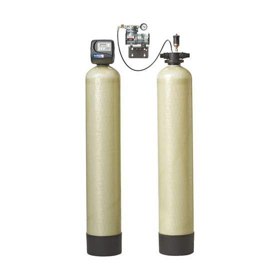
- Page 1 Installation and Operating Instructions For 3M™ Iron Reduction Filtration Systems MODELS: 3MAPPM150 3MAPPM200 Homeowner: Please retain for operation and future maintenance instructions.
- Page 3 Intended use: The 3M™ Series Iron Reduction Filtration System 3MAPPM Series is intended for use in reducing iron in water in homes and has not been evaluated for other uses. The system must be installed indoors near the point of entry of a home water line, and be installed by qualified professional installers according to these installation instructions.
-
Page 4: Table Of Contents
50 psi. The MAXIMUM PRESSURE for proper operation of the aeration tank is 50 psi. If you have a private water system, refer to page 2-1 to determine your system’s capability. If your system produces the required flow rate at 50 psi or higher, contact your Dealer/Installer or our Customer Care Team at 855-3M- WATER (855-369-2837). -
Page 5: Before Installation
10 ppm or less. If your water contains higher concentrations, contact your Dealer/Installer or our Customer Care Team at 855-3M-WATER (855-369-2837). The 3MAPPM Series Iron Reduction Filtration System is not bactericidal, i.e. it does not remove or kill “bacterial iron”. It reduces the iron and slime deposits in your plumbing line and fixtures upon which the bacteria may live, thus minimizing its effects. - Page 6 The addition of other water treatment devices (such as an acid neutralizer) may reduce the flow rate at the filter drain to an inadequate level to properly backwash the filter. If you are uncertain whether your flow rate is adequate, contact your Dealer/Installer or our Customer Care Team at 855-3M-WATER (855-369-2837) BEFORE installing the 3MAPPM Series Iron Reduction Filtration System, so that corrective action, if required, may be taken.
-
Page 7: Installation
SECTION 3: INSTALLATION Proper installation sequence of water conditioning equipment is very important. Refer to the diagram following for your particular water supply. TYPICAL INSTALLATION UNTREATED WATER FILTERED WATER FILTERED SOFT WATER PRESSURE FS1 FLOW SWITCH REGULATOR (NOT SUPPLIED) PRESSURE TANK CHECK VALVE BRINE... - Page 8 MOUNTING & SET-UP INSTRUCTIONS FOR GAST LOA-P109-AA COMPRESSOR UNIT Prior to using the system, some assembly and adjustments are required. Please locate these parts and ensure all items are present. These items are required to mount and set-up the GAST LOA-P109-AA Compressor assembly as well as to connect the tubing to the GAST LOA-P109-AA Compressor and aeration tank. •...
- Page 9 IMPORTANT NOTE It is suggested that a licensed electrician perform the wiring needs for this application to ensure the electrical connections are made in accordance with the NEC and local codes and standards. FS1 Specifications: Compressor Specifications 10 Amp Max @ 110 VAC a.
- Page 10 If any items intended for installation are missing at this time contact your Dealer/Installer or our Customer Care Team at 855-3M-WATER (855-369-2837) to notify them of this situation. Provide the model number and serial number when contacting your Dealer/Installer or our Customer Care Team.
- Page 11 Step 4 Once the filter media has been loaded, fill the media tank with water using a pail or water hose to saturate the media and expel any air out of the filtration system. Remove the centering tool from the distributor tube and the fill funnel from the opening of the mineral tank. Step 5 Use silicone lubricant to lubricate the distributor tube, control valve o-ring and pilot tube o-ring.
- Page 12 Step 8 The drain line connection can utilize either a 3/4” NPT or a 5/8” COMPRESSION connection. To utilize the 5/8” connection use the provided nut and insert sleeve with a 5/8” OD rigid or semi-rigid material. Slide the nut over the tubing or piping first, and then insert the sleeve into the piping or tubing until flush.
- Page 13 HOW TO SET TIME OF DAY STEP 1 Step 1) Press SET STEP 2 Regen Time Min. Fill Regen Days To Time Regen Step 2) Use ▲ and ▼ to adjust the current time hour. Time display will be 12 hour with PM indicator with 60 Hz line fre- quency detection on power-up.
- Page 14 TO SET TIME OF REGENERATION AND DAYS BETWEEN REGENERATION STEP 1 Follow these steps for inital set-up of or to make adjustments to the time of regeneration and/or the days between regenerations. The number of days between regenerations may need to be varied based on usage and water conditions.
- Page 15 If “E1” “E2” or “E3” appears on the display, contact your Dealer/Installer or our Customer Care Team at 855-3M-WATER (855-369-2837). These are error codes and will need to be resolved before the control valve will function. These codes indicate that the control valve did not function properly.
- Page 16 CAUTION To reduce the risk associated with property damage due to water leakage: • Read and follow Use Instructions before installation and use of this system. • Installation must comply with existing state or local plumbing codes. IMPORTANT NOTES • Failure to follow instructions may result in leakage and will void warranty. Special Service Instructions: Under normal circumstances removal of valve should never be required.
- Page 17 BYPASS VALVE OPERATION Figure 7 Figure 8 Figure 8 Figure 9 Figure 10 Figure 11 Figure 9 Figure 10 3-11...
-
Page 18: Backwashing Instructions
Number in box represents number of times, in 12 days, timer should be set to regenerate. Refer to HOW TO SET TIME CONTROL, page 3-9 to set timer. EXAMPLE: You have model 3MAPPM150, 4 in family and 8 ppm iron. Refer to SCHEDULE for model 3MAPPM150 and locate box intersected by 4 in family and 8 ppm iron. - Page 19 BACKWASHING FREQUENCY SCHEDULES MODEL: 3MAPPM150 Persons in IRON CONTENT (PPM) Family MODEL: 3MAPPM200 Persons in IRON CONTENT (PPM) Family...
- Page 20 Section 5: TROUBLESHOOTING - CONTROL VALVE Problem Possible Cause Solution 1. Timer does not display time of day a. AC adapter unplugged a. Connect power b. No electric power at outlet b. Repair outlet or use working outlet c. Damaged AC adapter c.
- Page 21 May require draining of water system or installation water (appears to Hydrogen Sulfide, Methane). of air relief control on the fillport cap of valve adapter contain small bubbles base, (contact Customer Care Team at 855-3M-WATER which do not quickly (855-369-2837). dissipate).
- Page 22 Replenishment of pH adjusting component of media may be required periodically, the frequency of which is dependent on raw water pH, manganese concentration and water consumption rate. Consult Customer Care Team at 855-3M-WATER (855-369-2837) for more information. For satisfactory performance, indicated durations should not be exceeded. Flow rates specified are adequate for normal residential applications.
- Page 23 Section 6: SPECIFICATIONS & OPERATING DATA (COMPONENTS PARTS LIST) Ref No. Description 3MAPPM150 3MAPPM200 Control Valve Complete w/Cover less Bypass W217530-003-3M W217750-003-3M Bypass Valve V3006 V3006 O-ring (Included with Item #1) V3180 V3180 Dome Hole Media Tank w/ Base 6238601-1054...
- Page 24 Section 6: SPECIFICATIONS & OPERATING DATA (COMPONENTS ASSEMBLIES) Iron Reduction Filtration System ASSEMBLIES AND COMPONENTS DRIVE CAP ASSEMBLY, DOWNFLOW PISTON, AND SPACE STACK ASSEMBLIES Reference No. Part No. Description Quantity V3005 Spacer Stack Assembly V3004 Drive Cap Assembly V3178 Drive Back Plate V3001 Piston Downflow Assembly V3135...
- Page 25 Section 6: SPECIFICATIONS & OPERATING DATA (FRONT COVER AND DRIVE ASSEMBLY) Reference No. Part No. Description Quantity V3175TC-01 Time Clock Front Cover Assembly V3107-01 Motor V3106-01 Drive Bracket & Spring Clip V3108TC Time Clock PC Board V3110 Drive Gear 12 x 36 V3109 Time Clock Cover V3002TC...
- Page 26 Section 6: SPECIFICATIONS & OPERATING DATA (QUICK CONNECT BYPASS) Part Number V3006 Reference No. Part No. Description Quantity V3151 Nut 1” Quick Connect V3150 Split Ring V3105 O-ring V3151 1” Quick Connect Nut V3150 Split Ring V3105 O-ring 215 V3191 Vertical Bypass Adapter (Not Shown)
- Page 27 Section 6: SPECIFICATIONS & OPERATING DATA (INSTALLATION FITTING AND ASSEMBLIES) Quick Connect Assemblies Part # V3007-02 1” Copper Brass Sweat Adapter Reference No. Part No. Description: 1” Brass Sweat Assembly Quantity V3151 1” Quick Connect Nut V3150 1” Quick Connect Split Ring V3105 1”...
- Page 28 Section 6: SPECIFICATIONS & OPERATING DATA (INSTALLATION FITTING AND ASSEMBLIES CONTINUED) Reference Part No. Description Quantity H4615 Elbow Locking Clip PKP10T58S-BLK 5/8” Insert Sleeve V3192 Quick Connect 3/4” Drain Elbow Nut V3158-01 Quick Connect 3/4” Drain Elbow V3163 O-ring 019 V3159-01 Drain Line Flow Control Retainer Assembly V3162-053...
-
Page 29: Maintenance
3M Purification Inc. recommends that you test your treated water pH once every three (3) months. When Iron is the only problem, a water pH needs to be 7.2 higher. - Page 30 3MAPPM Aeration Tank Maintenance (MAXAPRT) The following components that make up the “MAXAPRT” aeration tank will require maintenance from time to time. Air Release Valve (AR1). This is the air release device that controls the amount of air that is retained in the aeration tank. We recommend cleaning this air release valve at least once every six (6) months to help prevent plugging of the dip tube.
-
Page 31: Limited Warranty
CONDITION OF MERCHANTABILITY OR FITNESS FOR A PARTICULAR PURPOSE OR ANY IMPLIED WARRANTY OR CONDITION ARISING OUT OF A COURSE OF DEALING, CUSTOMER OR USAGE OF TRADE. If the Product fails to satisfy this Limited Warranty during the warranty period, 3M Purification Inc. will replace the Product or refund your Product purchase price. - Page 32 3M Purification Inc. 400 Research Parkway Meriden, CT 06450 INSTR8047 0613 855-3M-WATER (855-369-2837) 3M is a trademark of 3M Company. All other trademarks are property of their respective owners. © 2013 3M Company. All rights reserved. www.3MWater.com...
Need help?
Do you have a question about the 3MAPPM150 and is the answer not in the manual?
Questions and answers